
www.rotronic.comEnglish
12.1067.0103E
RMS-GW-868/915
Short Instruction Manual
1 GENERAL DESCRIPTION
Congratulations on your new RMS gateway. The
gateway transmits the data of the wireless data
loggers continuously to the RMS software by
Ethernet. These short instructions describe the
main functions of the device.
Please read this short manual and the instruction manual on
www.rotronic.com/rms carefully.
1.1 COMMISSIONING
The device must be supplied with 24 V (terminals: V+ / V-) or via PoE to be able to transmit data.
The gateway can be mounted easily with the wall bracket. The device is connected to the RMS
software by pairing.
Cloud integration
Integration of a LAN devices into the Rotronic Public Cloud requires for the local network Port 80 to
be enabled and a DHCP server must assign an IP address to the LAN device. For all other integra-
tions, please check the online manual.
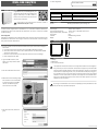
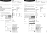
2 INTEGRATION OF THE GATEWAY (PAIRING) IN 6 STEPS
1. If you do not want to connect the device to the Rotronic Cloud, the server must be congured
in the device.
a. Connect the device to the local network and start the RMS conguration software.
b. Search for the device under
Device > Search > Network Device
. The software nds all RMS
devices in the local network.
c. Enter the host (server address) and the
URL
of the software services under Settings.
d. Finish conguration with
Write
.
2. Log into the RMS software / cloud.
Select
Tools > Setup > Devices > New >
LAN device
3. Enter the serial number of the device.
4. Wait until the device is ashing orange.
Press the button on the device briey,
as shown in the picture on the RMS
software. The LED ashes green,
when connection is succesful.
5. Enter the device name, channel and
group.
6. Finish conguration.
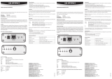
3 LED INDICATORS
Status LED Function Meaning
Connected Flashes green Status OK
Flashes red 2 times: no connection to the server
Not connected Flashes orange Device in pairing mode, push the button for integ-
ration into the software
4 ACCESSORIES
AC1321 Mounting kit with Allen key and mounting cone
5 TECHNICAL DATA
Power supply: 24 VDC ±10 % / <100 mA
Power supply requirements: 24 VDC ±10 % / >4 W / limited power source
Range of measurement / application: -40…70 °C
IP protection: IP65
Software: RMS Monitoring Software
Weight: 200 g
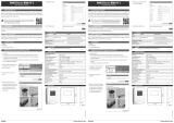
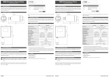
6 DIMENSIONS
7 DELIVERY PACKAGE
• Gateway
• Wall bracket
• Short instruction manual
This equipment has been tested and found to comply with the limits for a Class A digital de-
vice, pursuant to part 15 of the FCC Rules. These limits are designed to provide reasonable
protection against harmful interference when the equipment is operated in a commercial
environment. This equipment generates, uses, and can radiate radio frequency energy and,
if not installed and used in accordance with the instruction manual, may cause harmful
interference to radio communications. Operation of this equipment in a residential area is
likely to cause harmful interference in which case the user will be required to correct the
interference at his own expense.
Any changes or modications to this device not explicitly approved by manufacturer could
void your authority to operate this equipment.
105 mm
113 mm
38 mm

Deutsch www.rotronic.com
12.1067.0103D
RMS-GW-868/915
Kurzbedienungsanleitung
1 ALLGEMEINE BESCHREIBUNG
Herzlichen Glückwunsch zum Kauf des RMS-Ga-
teways. Das Gateway übermittelt die Daten der
Funkdatenlogger kontinuierlich per Ethernet an
die RMS-Software. Diese Kurzbedienunganlei-
tung beschreibt die wichtigsten Funktionen des
Geräts.
Bitte lesen Sie diese Kurzbedienungsanleitung sowie die Bedie-
nungsanleitung unter www.rotronic.com/rms genau durch.
1.1 INBETRIEBNAHME
Das Gerät muss mit 24 V (Klemmleiste: V+ / V-) oder PoE versorgt werden, damit die Daten übertra-
gen werden können. Das Gateway lässt sich einfach mit der Wandhalterung befestigen. Die Verbin-
dung mit der RMS-Software wird per Pairing hergestellt.
Cloud-Einbindung
Für die Einbindung eines LAN-Geräts in die Rotronic Public Cloud muss der lokale Netzwerkport 80
freigeschaltet sein und ein DHCP-Server muss dem LAN-Gerät eine IP-Adresse zuweisen. Hinweise
zu anderen Einbindungsmöglichkeiten nden Sie in der Online-Bedienungsanleitung.
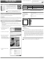
2 EINBINDUNG DES GATEWAYS (PAIRING) IN 6 SCHRITTEN
1. Falls das Gerät nicht mit der Rotronic Cloud verbunden werden soll, muss der Server im Gerät
eingestellt werden.
a. Gerät mit dem lokalen Netzwerk verbinden und RMS-Cong-Software starten.
b. Gerät suchen unter
Gerät > Suchen > Netzwerkgerät
. Die Software ndet alle RMS-Geräte
im lokalen Netzwerk.
c. Unter Einstellungen den Host (Adresse des Servers) & die URL des Software-Services angeben.
d. Konguration mit Schreiben abschliessen.
2. In die RMS-Software / Cloud einloggen.
Extras
> Setup > Geräte > Neu >
LAN-Gerät wählen
3. Seriennummer des Geräts eingeben.
4. Warten, bis das Gerät orange blinkt.
Knopf am Gerät kurz drücken,
wie in der Abbildung in der RMS-
Software dargestellt. Die LED blinkt grün,
wenn die Verbindung hergestellt wurde.
5. Gerätenamen, Kanal und Gruppe
eingeben.
6. Schliessen Sie die Konguration ab.
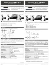
3 LED-ANZEIGEN
Statusanzeige LED-Funktion Bedeutung
Verbunden Blinkt grün Status OK
Blinkt rot 2-mal: keine Verbindung zum Server
Nicht verbunden Blinkt orange Gerät im Pairing-Modus, Taste zur Einbindung in
der Software drücken
4 ZUBEHÖR
AC1321 Montage-Kit mit Inbusschlüssel und Montagekonus
5 TECHNISCHE DATEN
Spannungsversorgung: 24 VDC ±10 % / <100 mA
Netzteil-Anforderungen: 24 VDC ±10 % / > 4 W / Stromquelle mit begrenzter Leistung
Mess- und Einsatzbereich: -40…70 °C
IP Schutzart: IP65
Software: RMS Monitoring-Software
Gewicht: 200 g
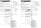
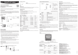
6 ABMESSUNGEN
7 LIEFERUMFANG
• Gateway
• Wandhalterung
• Kurzbedienungsanleitung
Dieses Gerät wurde getestet und entspricht den Grenzwerten für ein digitales Gerät der
Klasse A gemäss Teil 15 der FCC-Vorschriften. Diese Grenzwerte sollen einen angemesse-
nen Schutz vor schädlichen Störungen bieten, wenn das Gerät in einer gewerblichen Umge-
bung betrieben wird. Dieses Gerät erzeugt, nutzt und emittiert Hochfrequenzstrahlung und
kann sich bei einer nicht den Anweisungen entsprechenden Installation und Verwendung
negativ auf den Funkverkehr auswirken. Beim Betrieb dieses Geräts in einem Wohngebiet
wird wahrscheinlich schädliche Interferenz erzeugt, in welchem Fall der Benutzer die er-
forderlichen Gegenmassnahmen treffen muss, um die Interferenz auf eigene Kosten zu
beheben.
Änderungen oder sonstige vom Hersteller nicht ausdrücklich genehmigte Eingriffe in das
Gerät können Ihre Betriebszulassung für dieses Gerät hinfällig machen.
105 mm
113 mm
38 mm

Français www.rotronic.com
12.1067.0103F
RMS-GW-868/915
Mode d'emploi abrégé
1 DESCRIPTION GÉNÉRALE
Tous nos remerciements pour l’achat du gateway
RMS. Cet appareil transmet en continu, par
Ethernet, les données du logger radio au logiciel
RMS. Ce mode d’emploi abrégé décrit les fonc-
tions essentielles de cet instrument.
Veuillez lire avec attention ce manuel d’utilisation abrégé,
ainsi que le mode d’emploi que vous trouverez sur
www.rotronic.com/rms.
1.1 MISE EN SERVICE
L’appareil doit être alimenté en courant 24V (barrette de raccordement : V+ / V-) ou par PoE, an que
les données puissent être transmises. Le gateway peut être xé facilement avec le support mural.
La liaison avec le logiciel RMS est effectuée par couplage.
Liaison au Cloud
An d’intégrer un appareil LAN au Cloud public de Rotronic, le port réseau local 80 doit être activé
et un serveur DHCP doit lui attribuer une adresse IP. Vous trouverez des informations sur les autres
possibilités d’intégration dans le manuel en ligne.
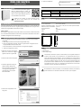
2 INTÉGRATION DU GATEWAY (COUPLAGE) EN 6 ÉTAPES
1. Au cas où l’appareil ne doive pas être relié au Cloud Rotronic, le serveur doit être paramétré
sur l’appareil.
a. Relier l’appareil au réseau local et démarrer le logiciel RMS-Cong.
b. Recherchez l
’
appareil avec Appareil
> Rechercher > Appareil réseau
. Le logiciel trouve tous
les appareils RMS connectés au réseau local.
c. Entrez l’hôte (adresse du serveur) et l’URL du service logiciel dans Réglages.
d. Terminer la conguration avec Écrire.
2. Effectuer la connexion dans le logiciel
RMS / Cloud. Choisir Extras
> Réglages >
Appareils > Nouveau > Appareil LAN
3. Entrer le numéro de série de l’appareil.
4. Attendez le clignotement orange sur
l’appareil. Appuyer brièvement le
bouton sur l’appareil, comme indiqué
sur l’image dans le logiciel RMS.
La LED clignote en vert, lorsque la
liaison a été établie.
5. Entrer le nom de l’appareil, le canal
et le groupe.
6. Terminez la conguration.
3 AFFICHAGE LED
Afchage de l’état Fonctions LED Signication
Raccordé Clignotement vert État OK
Clignotement rouge 2 fois : pas de liaison avec le serveur
Non raccordé Clignotement orange L’appareil est en mode de couplage, presser la
touche pour l’intégration au logiciel
4 ACCESSOIRES
AC1321 Kit de montage avec clé à 6 pans et cône de montage
5 CARACTÉRISTIQUES TECHNIQUES
Tension d’alimentation : 24 VCC ±10 % / <100 mA
Exigences de l’adaptateur secteur : 24 VCC ±10 % / > 4 W / Source de courant à puissance limitée
Gammes de mesure et d’utilisation : -40…70 °C
Type de protection IP : IP65
Logiciel : Logiciel RMS de monitoring
Poids : 200 g
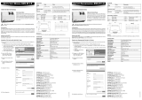
6 DIMENSIONS
7 FOURNITURES
• Gateway
• Support mural
• Mode d’emploi abrégé
Cet instrument a été testé et respecte les valeurs limites pour un appareil numérique de
la classe A, selon la partie 15 des prescriptions FCC. Ces valeurs limites offrent une pro-
tection raisonnable contre les interférences, pour une installation dans un environnement
commercial. Cet appareil produit, utilise et émet des rayonnements à haute fréquence et
peut avoir une inuence négative sur le trac radio s’il n’est pas installé et utilisé selon
les instructions fournies. L’utilisation dans une zone d’habitat provoquera probablement
des interférences nocives, dans ce cas, l’utilisateur doit entreprendre les contre-mesures
nécessaires, à ses frais, pour éliminer ces interférences.
Des modications et autres interventions, non formellement autorisées par le fabricant,
peuvent entraîner la non-conformité de l'autorisation de service pour cet appareil.
105 mm
113 mm
38 mm

Français www.rotronic.com
12.1067.0103F
RMS-GW-868/915
Manuale di istruzioni breve
1 DESCRIZIONE GENERALE
Congratulazioni per il nuovo gateway RMS. Il
gateway trasmette continuamente i dati dei data
logger wireless al software RMS via Ethernet.
Queste istruzioni brevi descrivono le funzioni
principali dello strumento.
Si prega di leggere con cura il presente manuale breve e il manua-
le di istruzioni su www.rotronic.com/rms.
1.1 COMMISSIONING
Lo strumento deve essere alimentato a 24 V (terminali: V+ / V-) oppure via PoE per riuscire a trasmet-
tere i dati. Il gateway si monta facilmente con una staffa a parete. Lo strumento viene connesso al
software RMS software mediante pairing.
Integrazione nel cloud
L'integrazione di uno strumento LAN nel Rotronic Public Cloud (cloud pubblico Rotronic) richiede
l'abilitazione della porta 80 di rete locale, inoltre un server DHCP deve assegnare un indirizzo IP allo
strumento LAN. Per tutti gli altri tipi di integrazione controllare il manuale online.
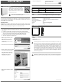
2 INTEGRAZIONE DEL GATEWAY (PAIRING) IN 6 PASSAGGI
1. Se non si intende connettere lo strumento al Cloud Rotronic, il server deve essere congurato
nello strumento.
a. Connettere lo strumento alla rete locale ed avviare il software di congurazione RMS.
b. Cercare lo strumento con il percorso
Device > Search > Network Device (Strumento > Ricerca >
Strumento di rete)
. Il software individua tutti gli strumenti RMS nella rete locale.
c. Inserire lo host (indirizzo del server) e l'
URL
dei servizi software in Impostazioni.
d. Terminare la congurazione con
Write (Scrivi)
.
2. Effettuare il login al software / cloud
RMS. Selezionare
Tools > Setup >
Devices > New > LAN device (Tool >
Congurazione > Strumenti > Nuovo >
Strumento LAN)
3. Inserire il num. di serie dello strumento.
4. Attendere nché lo strumento lampeggia
in arancione. Premere brevemente il
tasto sullo strumento, come mostra
l'immagine nel software RMS. Il LED
lampeggia in verde, quando la
connessione va a buon ne.
5. Digitare il nome strumento, il canale e
il gruppo.
6. Terminare la congurazione.
3 INDICATORI LED
Stato Funzione LED Signicato
Connesso Lampeggia in verde Stato OK
Lampeggia in rosso 2 volte: nessuna connessione al server
Non connesso Lampeggia in
arancione
Strumento in modalità pairing, premere il tasto per
l'integrazione nel software
4 ACCESSORI
AC1321 Kit di montaggio con chiave a brugola e cono di montaggio
5 DATI TECNICI
Alimentatore: 24 VDC ±10% / <100 mA
Requisiti alimentatore: 24 VDC ±10% / >4 W / fonte di alimentazione limitata
Campo di misura / applicazione: -40…70 °C
Protezione IP: IP65
Software: Software di monitoraggio RMS
Peso: 200 g
6 DIMENSIONI
7 DOTAZIONE
• Gateway
• Staffa a parete
• Manuale di istruzioni breve
Il presente apparecchio è stato testato e ritenuto conforme ai limiti per uno strumento dig-
itale di Classe A, in base a quanto prescritto dalla Parte 15 del Regolamento FCC. Tali limiti
sono concepiti per fornire una ragionevole protezione dalle interferenze dannose prodotte
dal funzionamento dell'apparecchio in impianti commerciali. Il presente apparecchio gen-
era, usa e può irradiare energia a radio frequenza e, se non installato ed utilizzato in confor-
mità al manuale di istruzioni, potrebbe causare interferenze dannose con le comunicazioni
radio. È probabile che il funzionamento del presente apparecchio in un'area residenziale
possa causare interferenze dannose, nel qual caso l'utente sarà obbligato ad eliminare le
interferenze a proprie spese.
Cambiamenti o modiche apportati a questo strumento, non espressamente approvati dal
fabbricante, potrebbero annullare per l'utilizzatore l'autorizzazione all'uso dell'apparecchio.
105 mm
113 mm
38 mm
-
 1
1
-
 2
2
-
 3
3
-
 4
4


Rotronic GAT868 Manuale utente
- Tipo
- Manuale utente
- Questo manuale è adatto anche per
in altre lingue
- English: Rotronic GAT868 User manual
- français: Rotronic GAT868 Manuel utilisateur
- Deutsch: Rotronic GAT868 Benutzerhandbuch
Documenti correlati
-
 Rotronic RMS-LOG-L Manuale utente
-
 Rotronic RMS-D-L Manuale utente
-
 Rotronic RMS-LOG-868 Short Instruction Manual
-
 Rotronic RMS-DI-L-R Manuale utente
-
Rotronic RMS-CONVERTER-100 Short Instruction Manual
-
Rotronic RMS-MLOG-868 Manuale utente
-
 Rotronic Lan interface Short Instruction Manual
-
 Rotronic PCDS Manuale utente
-
 Rotronic HCD Short Instruction Manual
-
 Rotronic HF5NEW Manuale utente


