
English Deutsch
12.1075.0103E
12.1075.0103D
www.rotronic.comwww.rotronic.com
RMS DISPLAY: RMS-D-L
Kurzbedienungsanleitung
RMS DISPLAY: RMS-D-L
Short instruction manual
1 ALLGEMEINE BESCHREIBUNG
Herzliche Gratulation zum Kauf des RMS Display. Das Rotronic RMS Display ist ein frei kongurier-
bares Display. Als Ferndisplay kann es optimal dort platziert werden, wo es dem Betrachter am
besten passt. Das Display ist in der Lage Messwerte, Zustände und Alarme von RMS-Produkten
darzustellen. Diese Kurzbedienungsanleitung beschreibt die wichtigsten Funktionen des Gerätes.
Bitte lesen Sie diese Kurzbedienungsanleitung und die Betriebsanlei-
tung sorgfältig durch auf https://service.rotronic.com/manual/ oder
scannen Sie den QR-Code um direkt die Betriebsanleitung zu öffnen.
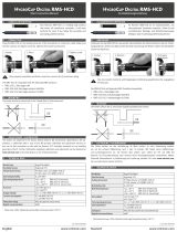
1.1 INBETRIEBNAHME
Das Gerät muss mit 24V (Klemmleiste: V+ / V-) oder PoE versorgt werden, damit die Daten übertra-
gen werden können. Der Display lässt sich einfach mit der Wandhalterung befestigen. Die Verbin-
dung mit der RMS-Software wird per Pairing hergestellt.
1.2 WICHTIG: PORT80, DHCP
Um ein LAN-Gerät zu integrieren, muss der Port 80 (standardmäßig, bitte mit Ihrer IT-Abteilung
klären) in Ihrem Netzwerk aktiviert sein und ein DHCP-Server (feste IP-Adressen nden Sie in Ihrer
IT-Abteilung) muss dem Gerät die IP-Adresse zuweisen.
2 LIEFERUMFANG
• Display
• Wandhalterung
• Kurzbedienungsanleitung
3 EINBINDEN DES DISPLAYS (PAIRING) IN 6 SCHRITTEN
1. Falls das Gerät nicht mit der Rotronic Cloud verbunden werden soll, muss der Server im Gerät
eingestellt werden.
a. Gerät mit dem lokalen Netzwerk verbinden und RMS-Cong-Software starten.
b. Gerät suchen unter Gerät > Suchen > Netzwerkgerät. Die Software ndet alle RMS-Geräte
im lokalen Netzwerk.
c. Unter Einstellungen den Host (Adresse des Servers) und die URL des Software-Services
angeben.
d. Konguration abschliessen mit Schreiben.
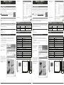
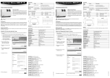
2. Einloggen in die RMS-Software /
Cloud. Unter Extras > Setup >
Geräte > Neu LAN-Gerät.
3. Seriennummer des Gerätes
eingeben.
4. Warten Sie bis das Gerät orange
blinkt. Drücken Sie kurz die Taste
am Gerät, wie in der Abbildung
der RMS-Software dargestellt.
Die LED blinkt grün, wenn die
Verbindung erfolgreich ist.
1 GENERAL DESCRIPTION
Congratulations on your new RMS display. The Rotronic RMS display is a freely congurable dis-
play. As a remote display, it can be placed optimally where it suits the viewer best. The display is
able to show the measured values, states and alarms of RMS products. These short instructions
describe the main functions of the device.
Please read these short instructions and the instruction manual at
https://service.rotronic.com/manual/ carefully or scan the QR code to
open the instruction manual directly.
1.1 COMMISSIONING
The device must be supplied with 24 V (terminals: V+ / V-) or PoE to be able to transmit data. The
display can be mounted easily with the wall bracket. The device is connected to the RMS software
by pairing.
1.2 WICHTIG: PORT80, DHCP
To integrate a LAN device, port 80 (per standard, please conrm with your IT department) must be
enabled in your network and a DHCP server (for xed IP addresses, please see your IT department)
must assign the IP address to the device.
2 DELIVERY PACKAGE
• Display
• Wall bracket
• Short instruction manual
3 INTEGRATION OF THE DISPLAY (PAIRING) IN 6 STEPS
1. If you do not want to connect the device to the Rotronic Cloud, the server must be congured
in the device.
a. Connect the device to the local network and start the RMS conguration software.
b. Search for the device under Device > Search > Network Device. The software nds all
RMS devices in the local network.
c. Enter the host (server address) and the URL of the software-services under Settings.
d. Finish conguration with Write.
2. Log into the RMS software / cloud.
Select Tools > Setup > Devices >
New > LAN device.
3. Enter the serial number of the
device.
4. Wait until the device ashes
orange. Briey press the button on
the device as shown in the picture
of the RMS software. The LED
ashes green when connection
is successful.
5. Platzieren Sie die gewünschten
Geräte-Einstellungen.
6. Konguration abschliessen.
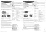
4 LED-ANZEIGE
Taste Modus Statusanzeige
Pairing
1 s Bestätigt Pairing n x orange, die Anzeige blickt
während die Pairinganfrage offen ist
Gerätestatus anzeigen
Automatisch
(alle 5 Sekunden)
Zeigt den aktuellen Status an 1 x grün, Verbindung zum Server stimmt.
2 x rot, keine Serververbindung
5 ZUBEHÖR
AC1321 Montage-Kit mit Inbusschlüssel und Montagekonus
6 TECHNISCHE DATEN
Allgemeine Spezikationen
Gerätetyp RMS-Display
Anzeige Messstellen Bis zu 4 Messstellen
Einsatzbereich -20…70 °C / 0…100 %rF
Lagerbedingungen -20…30 °C / 0…95 %rF
Spannungsversorgung 24 VDC ± 10% / <100 mA / PoE: 802.3 / af-2003, Klasse 1
Netzteil-Anforderungen 24 VDC ±10 % / >4 W / leistungsbegrenzt
Messintervall 10 s
Schnittstelle Ethernet
Protokolle HTTP
Konformität mit Standards
FDA-/GAMP-Direktiven FDA CFR21 Part 11 / GAMP 5
Gehäuse / Mechanik
Gehäusematerial PC, ABS
Brandschutzklasse UL94-V2
Abmessungen 105 x 113 x 38 mm
Abmessung Display 2,26 Zoll
IP-Schutzgrad IP65
Gewicht 206 g
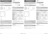
7 ABMESSUNGEN
5. Congure the device.
6. Finish conguration.
4 LED INDICATORS
Button Mode Status
Pairing
1 s Conrms pairing n x orange, the indicator ashes
while the pairing request is running
Show device status
Automatic
(every 5 seconds)
Shows the current status 1 x green, connection to server okay
2 x red, no server connection
5 ACCESSORIES
AC1321 Mounting kit with Allen key and mounting cone
6 TECHNICAL DATA
General specications
Device type RMS Display
Display of measuring points Up to 4 measuring points
Range of application -20...70 °C / 0...100 %RH
Storage conditions -20...30 °C / 0...95 %RH
Power supply 24 VDC ±10 % / <100 mA / PoE: 802.3 / af-2003, Class 1
AC adapter requirements 24 VDC ±10 % / >4 W / power-limited
Measurement interval 10 s
Interface Ethernet
Protocols HTTP
Conformity with standards
FDA / GAMP directives FDA CFR21 Part 11 / GAMP 5
Housing / Mechanical parts
Housing material PC, ABS
Fire protection class UL94-V2
Dimensions 105 x 113 x 38 mm
Display diagonal 2.26 inch
IP protection class IP65
Weight 206 g
7 DIMENSIONS
105 mm
113 mm
38 mm
105 mm
113 mm
38 mm
105 mm
113 mm
38 mm
105 mm
113 mm
38 mm

www.rotronic.comFrançais Italianowww.rotronic.com
12.1075.0103F
12.1075.0103I
DISPLAY RMS: RMS-D-L
Manuale di istruzioni breve
AFFICHAGE RMS : RMS-D-L
Mode d'emploi abrégé
1 DESCRIZIONE GENERALE
Congratulazioni per l'acquisto del display RMS. Il display Rotronic RMS è un display liberamen-
te congurabile. Come display remoto può essere posizionato in modo ottimale proprio nel pun-
to ritenuto migliore dall'osservatore. Il display è in grado di visualizzare valori di misura, stati e
allarmi di prodotti RMS. Il presente manuale d'istruzioni breve descrive le funzioni principali dello
strumento.
Leggere attentamente il presente manuale di istruzioni breve e le istru-
zioni per l'uso su https://service.rotronic.com/manual/ oppure scansi-
onare il codice QR per aprire direttamente le istruzioni per l'uso.
1.1 MESSA IN SERVIZIO
Lo strumento necessita di alimentazione a 24 V (morsettiera: V+ / V-) o PoE, per poter trasmettere
i dati. Il display può essere ssato semplicemente con il supporto a parete. Il collegamento con il
software RMS viene stabilito tramite pairing (associazione).
1.2 WICHTIG: PORT80, DHCP
Per integrare un dispositivo LAN, la porta 80 (per standard, confermare con il proprio reparto IT)
deve essere abilitata nella rete e un server DHCP (per indirizzi IP ssi, vedere il proprio reparto IT)
deve assegnare l'indirizzo IP al dispositivo.
2 DOTAZIONE
• Display
• Supporto a parete
• Manuale d'istruzioni breve
3 COME ASSOCIARE IL DISPLAY (PAIRING) IN 6 PASSAGGI
1. Se lo strumento non deve essere collegato al cloud Rotronic, occorre impostare il server nello
strumento.
a. Collegare lo strumento alla rete locale e lanciare il software di congurazione RMS.
b. Cercare lo strumento in Strumento > Cerca > Strumento di rete. Il software individua tutti gli
strumenti RMS della rete locale.
c. In Impostazioni indicare l'host (indirizzo del server) e l'URL del servizio software.
d. Terminare la congurazione con Scrivi.
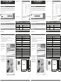
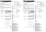
2. Login nel software / cloud RMS.
Seguire il percorso Extra >
Congurazione > Strumenti >
Nuovo Strumento LAN
3. Digitare il numero di serie dello
strumento.
4. Attendere no al momento in cui lo
strumento lampeggia in arancio.
Premere brevemente il tasto
sullo strumento, come mostra
l'immagine del software RMS.
Il LED lampeggia in verde, se il
collegamento è andato a buon ne.
1 DESCRIPTION GÉNÉRALE
Tous nos remerciements pour l’achat de l’afchage RMS. Le dispositif d’afchage RMS de Rotronic
est u appareil à conguration libre. En tant qu’afchage déporté, il peut être placé à l’endroit qui
convient le mieux à son utilisateur. L’afchage est en mesure de représenter les valeurs de mesure,
états et alarmes des produits RMS. Ce mode d’emploi abrégé se limite à la description des fonc-
tions essentielles de cet appareil.
Veuillez lire avec attention ce manuel d’utilisation abrégé, ainsi que le
mode d’emploi que vous trouverez sur https://service.rotronic.com/
manual/ ou scannez le code QR pour l’ouvrir directement.
1.1 MISE EN SERVICE
L’appareil doit être alimenté en courant 24V (barrette de raccordement: V+ / V-), an que les
données puissent être transmises. Le dispositif d’afchage peut être xé facilement avec le sup-
port mural. La liaison avec le logiciel RMS est effectuée par couplage.
1.2 IMPORTANT: PORT80, DHCP
Pour intégrer un périphérique LAN, le port 80 (par défaut, veuillez le conrmer auprès de votre
service informatique) doit être activé dans votre réseau et un serveur DHCP (pour les adresses
IP xes, veuillez consulter votre service informatique) doit attribuer l'adresse IP au périphérique.
2 LIVRÉ AVEC
• Dispositif d’afchage
• Support mural
• Mode d'emploi abrégé
3 INTÉGRATION DU AFFICHAGE (COUPLAGE) EN 6 ÉTAPES
1. Au cas où l’appareil ne doive pas être relié au Cloud Rotronic, son serveur interne doit être
paramétré.
a. Relier l’appareil au réseau local et démarrer le logiciel RMS-Cong.
b. Rechercher l’appareil avec Appareil > Rechercher > Appareil réseau. Le logiciel trouve tous
les appareils RMS connectés au réseau local.
c. Entrer l’hôte (adresse du serveur) et l’URL du service logiciel dans Réglages.
d. Terminer la conguration avec Écrire.
2. Effectuer la connexion avec
le logiciel RMS / Cloud. Sous
Extras > Conguration > Appareil
> Nouveau périphérique LAN
3. Entrer le numéro de série de
l’appareil.
4. Attendez le clignotement orange
sur l’appareil. Pressez brièvement
le bouton sur l’appareil, comme
indiqué sur l’image dans le logiciel
RMS. La LED clignote en vert,
lorsque la liaison a été établie.
5. Impostare lo strumento come
richiesto.
6. Terminare la congurazione.
4 INDICATORE LED
Tasto Modalità Indicazione di stato
Pairing
1 s Pairing confermato n volte arancione, l'indicatore lampeggia
mentre la richiesta di pairing è in corso
Indicazione di stato dello strumento
Automatica
(ogni 5 secondi)
Indica lo stato attuale 1 volta verde, connessione al server corretta.
2 volte rosso, nessuna connessione al server
5 ACCESSORI
AC1321 Kit di montaggio con chiave a brugola e cono di montaggio
6 DATI TECNICI
Speciche generali
Descrizione Display RMS
Visualizzazione dei punti di misura Fino a 4 punti di misura
Campo di lavoro -20…70 °C / 0…100 %UR
Condizioni di conservazione -20…30 °C / 0…95 %UR
Alimentazione 24 VDC ± 10% / <100 mA / PoE: 802.3
af-2003, Classe 1
Requisiti alimentatore 24 VDC ±10 % / >4 W / a potenza limitata
Intervallo di misura 10 s
Interfaccia Ethernet
Protocolli HTTP
Conformità agli standard
Direttive FDA/GAMP FDA CFR21 Part 11 / GAMP 5
Housing/ Meccanica
Materiale housing PC, ABS
Classe antincendio UL94-V2
Dimensioni 105 x 113 x 38 mm
Dimensioni display 2,26 pollici
Grado di protezione IP IP65
Peso 206 g
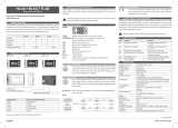
7 DIMENSIONI
5. Effectuer les réglages appareil
souhaités.
6. Terminer la conguration.
4 AFFICHAGE LED
Touche Mode Afchage de l’état
Couplage
1 s Conrme le couplage n x orange, l’afchage clignote pendant que la
demande de couplage est ouverte
Afcher l’état de l’appareil
Automatique (toutes
les 5 secondes)
Afche le statut
actuel
1 fois vert, la liaison au serveur est correcte.
2 fois rouge, pas de liaison au serveur
5 ACCESSOIRES
AC1321 Kit de montage avec clé à 6 pans et cône de montage
6 CARACTÉRISTIQUES TECHNIQUES
Spécications générales
Type d’appareil Afchage RMS
Afchage des postes de mesure Jusqu’à 4 postes de mesure
Gamme d’utilisation -20…70 °C / 0…100 %HR
Conditions de stockage -20…30 °C / 0…95 %HR
Tension d’alimentation 24 VCC ± 10% / <100 mA / PoE: 802.3
af-2003, classe 1
Exigences réseau 24 VCC ±10 % / >4 W / limitation de puissance
Intervalle de mesure 10 s
Interface Ethernet
Protocole HTTP
Conformité avec les standards
Directives FDA/GAMP FDA CFR21 partie 11 / GAMP 5
Boîtier / Mécanique
Matériau du boîtier PC, ABS
Classe de protection incendie UL94-V2
Dimensions 105 x 113 x 38 mm
Dimensions de l’afchage 2,26 pouces
Degré de protection IP IP65
Poids 206 g
7 DIMENSIONS
105 mm
113 mm
38 mm
105 mm
113 mm
38 mm
105 mm
113 mm
38 mm
105 mm
113 mm
38 mm
-
 1
1
-
 2
2


Rotronic RMS-D-L Manuale utente
- Tipo
- Manuale utente
- Questo manuale è adatto anche per
in altre lingue
- English: Rotronic RMS-D-L User manual
- français: Rotronic RMS-D-L Manuel utilisateur
- Deutsch: Rotronic RMS-D-L Benutzerhandbuch
Documenti correlati
-
 Rotronic GAT868 Manuale utente
-
Rotronic RMS-CONVERTER-100 Short Instruction Manual
-
 Rotronic RMS-LOG-L Manuale utente
-
 Rotronic RMS-DI-L-R Manuale utente
-
 Rotronic RMS-LOG-868 Short Instruction Manual
-
Rotronic RMS-MLOG-868 Manuale utente
-
 Rotronic PCDS Manuale utente
-
 Rotronic HL-1D / BL-1D / TL-1D Manuale del proprietario
-
 Rotronic HCD Short Instruction Manual
-
 Rotronic HygroLog HL20 Manuale utente


