Marantz SR 7200 Manuale utente
- Categoria
- Ricevitori AV
- Tipo
- Manuale utente

Model SR7200 User Guide
AV Surround Receiver
R

ENGLISH
WARRANTY
For warranty information, contact your local Marantz distributor.
RETAIN YOUR PURCHASE RECEIPT
Your purchase receipt is your permanent record of a valuable purchase.
It should be kept in a safe place to be referred to as necessary for
insurance purposes or when corresponding with Marantz.
IMPORTANT
When seeking warranty service, it is the responsibility of the consumer
to establish proof and date of purchase. Your purchase receipt or in-
voice is adequate for such proof.
FOR U.K. ONLY
This undertaking is in addition to a consumer's statutory rights and does
not affect those rights in any way.
FRANÇAIS
GARANTIE
Pour des informations sur la garantie, contacter le distributeur local
Marantz.
CONSERVER L'ATTESTATION D'ACHAT
L'attestation d'achat est la preuve permanente d'un achat de valeur. La
conserver en lieu sur pour s'y reporter aux fins d'obtention d'une
couverture d'assurance ou dans le cadre de correspondances avec
Marantz.
IMPORTANT
Pour l'obtention d'un service couvert par la garantie, il incombe au cli-
ent d'établir la preuve de l'achat et d'en corroborer la date. Le reçu ou la
facture constituent des preuves suffisantes.
DEUTSCH
GARANTIE
Bei Garantiefragen wenden Sie sich bitte an Ihren Marantz-Händler.
HEBEN SIE IHRE QUITTING GUT AUF
Die Quittung dient Ihnen als bleibende Unterlage für Ihren wertvollen
Einkauf Das Aufbewahren der Quittung ist wichtig, da die darin
enthaltenen Angaben für Versicherungswecke oder bei Korrespondenz
mit Marantz angeführt werden müssen.
WICHTIG!
Bei Garantiefragen muß der Kunde eine Kaufunterlage mit Kaufdatum
vorlegen. Ihren Quittung oder Rechnung ist als Unterlage ausreichend.
NEDERLANDS
GARANTIE
Voor inlichtingen omtrent garantie dient u zich tot uw plaatselijke Marantz.
UW KWITANTIE, KASSABON E.D. BEWAREN
Uw kwitantie, kassabon e.d. vormen uw bewijs van aankoop van een
waardevol artikel en dienen op een veilige plaats bewaard te worden
voor evt, verwijzing bijv, in verbend met verzekering of bij correspondentie
met Marantz.
BELANGRIJK
Bij een evt, beroep op de garantie is het de verantwoordelijkheid van de
consument een gedateerd bewijs van aankoop te tonen. Uw kassabon
of factuurzijn voldoende bewijs.
ESPAÑOL
GARANTIA
Para obtener información acerca de la garantia póngase en contacto
con su distribuidor Marantz.
GUARDE SU RECIBO DE COMPRA
Su recibo de compra es su prueba permanente de haber adquirido un
aparato de valor, Este recibo deberá guardarlo en un lugar seguro y
utilizarlo como referencia cuando tenga que hacer uso del seguro o se
ponga en contacto con Marantz.
IMPORTANTE
Cuando solicite el servicio otorgado por la garantia el usuario tiene la
responsabilidad de demonstrar cuá¥do efectuó la compra. En este caso,
su recibo de compra será la prueba apropiada.
ITALIANO
GARANZIA
L’apparecchio è coperto da una garanzia di buon funzionamento della
durata di un anno, o del periodo previsto dalla legge, a partire dalla data
di acquisto comprovata da un documento attestante il nominativo del
Rivenditore e la data di vendita. La garanzia sarà prestata con la
sostituzione o la riparazione gratuita delle parti difettose.
Non sono coperti da garanzia difetti derivanti da uso improprio, errata
installazione, manutenzione effettuata da personale non autorizzato o,
comunque, da circostanze che non possano riferirsi a difetti di
funzionamento dell’apparecchio. Sono inoltre esclusi dalla garanzia gli
interventi inerenti l’installazione e l’allacciamento agli impianti di
alimentazione.
Gli apparecchi verranno riparati presso i nostri Centri di Assistenza
Autorizzati. Le spese ed i rischi di trasporto sono a carico del cliente.
La casa costruttrice declina ogni responsabilità per danni diretti o indiretti
provocati dalla inosservanza delle prescrizioni di installazione, uso e
manutenzione dettagliate nel presente manuale o per guasti dovuti ad
uso continuato a fini professionali.
PORTUGUÊS
GARANTIA
Para informações sobre a garantia, contactar o distribuidor Marantz lo-
cal.
GUARDAR O RECIBO DE COMPRA
O recibo é o registo permanente da compra que fez. Deve ser guardado
num local seguro, para ser apresentado em questões relacionadas com
o seguro ou para quando tiver de contactar a Marantz.
IMPORTANTE
Quando procurar assisténcia técnica ao abrigo da garantia, é da
responsabilidade do consumidor estabelecer a prova e data de compra.
O recibe é prova adequada.
SVENSKA
GARANTI
För information om garantin, kontakta Marantz lokalagent.
SPAR KVITTOT
Kvittot är ett inköpsbevis på en värdefull vara. Det skall förvaras säkert
och hänvisas till vid försäkringsfall eller vidkorrespondens mod Marantz.
VIKTIGT
Fö att garantin skall gälla är det kundens sak att framställa bevis och
datum om köpet. Kvitto eller faktura är tillräokligt bevis fö detta.
DANSK
GARANTI
Henvend dem til Deres MARANTZ-forhandler angående inrformation om
garantien.
GEM DERES KVITTERING
Deres købskvittering er Deres varige bevis på et dyrt køb. Den bør
gemmes godt og anvendes som bevis, hvis De vil tegne en forsikring,
eller hvis De kommunikerer med Marantz.
VIGTIGT
Det påhviler forbrugeren at skaffe bevis for købet og købsdatoen, hvis
han eller hun ønsker garantiservice. Deres købskvittering eller faktura er
et fuldgyldigt bevis herpå.
i

English
To ventilate the unit, do not install the unit in a rack or bookshelf, and
note the followings.
- Do not touch the top of the enclosure during operation.
- Do not block the openings in the enclosure during operation.
- Do not insert objects beneath the unit.
- Do not block the ventilation slots at the top of the unit.
Do not place anything about 1 meter above the top panel.
- Make a space of about 0.2 meter around the unit.
Français
Pour que l'appareil puisse être correctement ventilé, ne pas l'installer
dans un meuble ou une bibliothèque et respecter ce qui suit.
- Ne pas toucher le dessus du coffret.
- Ne pas obstruer les ouïes de ventilation du coffret pendant le
fonctionnement.
- Ne placer aucun objet sous l'appareil.
- Ne pas obstruer les ouães de ventilation du panneau supérieur. Ne
placer aucun objet à moins d'un mètre environ du panneau supérieur.
- Veiller à ce qu'aucun objet ne soit à moins de 0,2 mètre des côtés de
l'appareil.
Deutsch
Um eine einwandfreie Belüftung des Geräts zu gewährleisten, darf das
Gerät nicht in einem Gestell oder Bücherregal aufgestellt werden; die
folgenden Punkte sind besonders zu beachten:
- Während des Betriebs das Oberteil des Gehäuses nicht berühren.
- Während des Betriebs die Öffnungen im Gehäuse nicht blockieren.
- Keine Gegenstände in das Gerät einführen.
- Die Belüftungsschlitze an der Oberseite des Geräts dürfen nicht
blockiert werden. Darauf achten, daß über dem Gerät ein Freiraum
von mindestens 1 meter vorhanden ist.
- Auf allen Geräteseiten muß ein Zwischenraum von ungefähr 0,2 meter
vorhanden sein.
Nederlands
Installeer het toestel niet in een rek of boekenkast waar de ventilatie
mogelijk wordt gehinderd. Let tevens op de volgende punten:
- Raak de bovenkant van het toestel niet aan als het in gebruik is.
- Blokkeer de openingen van het toestel niet als het in gebruik is.
- Plaats geen onderwerpen onder het toestel.
- Blokkeer de ventilatie-openingen aan de bovenkant van het toestel
niet. Zorg dat er tenminste 1 meter vrije ruimte boven het toestel is.
- Zorg dat er 0,2 meter vrije ruimte rond het toestel is.
Español
Para ventilar la unidad no la instale en una estantería ni estante para
libros, y tenga en cuenta lo siguiente:
- No toque la parte superior de la caja durante el funcionamiento.
- No tape las ranuras en la caja durante el funcionamiento
- No ponga objetos debajo de la unidad.
- No tape las ranuras de ventilación de la parte superior de la unidad.
No ponga nada a menos de 1 metro por encima del panel superior.
- Deje un espacio de unos 0,2 metro alrededor de la unidad.
Italiano
Perch é l'unità possa essere sempre ben ventilata, non installarla in
scaffali o librerie e tenere presente quanto segue.
- Non toccare la parte superiore del rivestimento durante il
funzionamento.
- Non bloccare le aperture sul rivestimento durante il funzionamento.
- Non inserire oggetti al di sotto dell'unità.
- Non bloccare le fessure di ventilazione sopra l'unità.
Non posare nulla per circa un metro sopra il pannello superiore.
- Lasciare 0,2 metro liberi tutto intorno l'unità.
Português
Para ventilar o aparelho, não instalá-lo dentro duma estante ou algo
similar, e observar as seguintes recomendações:
- Não tocar a parte superior do aparelho durante a operação.
- Não bloquear as aberturas do aparelho durante a operação.
- Não insertar objectos debaixo do aparelho.
- Não bloquear as aberturas de ventilação na parte de cima do
aparelho. Deixar um espaço completamente livre de cerca de 1 metro
acima do painel superior.
- Deixar um espaço de cerca de 0,2 metro ao redor do aparelho.
Svenska
För att ventilera enheten, ställ den inte i ett ställ eller bokhylla och tänk
på följande.
- Vidrör inte ytterhöljets ovansida under pågående drift.
- Blockera inte öppningarna i ytterhöljet under pågående drift.
- Stick inte in föremål under enheten.
- Blockera inte ventialtionshålen ovanpå enheten.
Placera inte någonting närmare än 1 meter ovanför apparaten eller
enheten.
- Se till att det finns omkring 0,2 meter fri plats runt omkring enheten.
Dansk
Anbring ikke apparatet i et rack eller en boghylde, da dette kan bloke
luftcirkulationen omkring apparatet. Iagttag ligeledes følgende:
- Berør ikke oversiden af kabinettet under anvendelsen.
- Bloker ikke åbningerne i kabinettet under anvendelsen.
- Stik ikke genstande ind under apparatet.
- Bloker ikke ventilationsåbningerne ovenpå apparatet.
Anbring ikke noget nærmere end 1 m over apparatets overside,
- Sørg for, at der er et frit område på omkring 0,2 m omkring apparatet.
CE MARKING
English
The SR7200 is in conformity with the EMC directive and low-voltage directive.
Français
Le SR7200 est conforme à la directive EMC et à la directive sur les basses tensions.
Deutsch
Das Modell SR7200 entspricht den EMC-Richtlinien und den Richtlinien für Niederspannungsgeräte.
Nederlands
De SR7200 voldoet aan de EMC eisen en de vereisten voor laag-voltage.
Español
El SR7200 está de acuerdo con las normas EMC y las relacionadas con baja tensión.
Italiano
Il SR7200 è conforme alle direttive CEE ed a quelle per i bassi voltaggi.
Português
O SR7200 conforma com as diretrizes EMC e de baixa voltagem.
Svenska
SR7200 är tillverkad i enlighet med EMC direktiven och direktiven för lågvoltsutrusning.
Dansk
Model SR7200 er i overensstemmelse med EMC-direktiveet og direktivet om lavspænding.
ii

AV SURROUND RECEIVER SR7200
UP
SURROUND
VOLUME
DOWN
DSS/VCR2 AUX
VCR1
DVD
TV CD
CDR/MD
TAPE
TUNER
MEMORY
TUNING/PRESET
MODE
F/P
CLEAR
NIGHT
ATT
DISPLAY OFF
SLEEP
S-DIRECT
DIMMER
MUTE
A/D7CH INPUT
POWER ON/OFF
PHONES
STANDBY
AUX INPUT
BSPEAKERSA
MULTI ROOM
MULTI ROOM
S-VIDEO VIDEO L AUDIO R
A
SLEEP
MUTE
ANALOG
DIGITAL
MLP PCM
RF AUTO LOCK CIRCLE SURROUND EX MPEG DIRECT MEMORY PRESET SW LFE
SRSCSLRTTAPTYAUTOTUNEDDSP SOUNDVIRTUAL
1 2 3 4 5 6
DIGITALDTS
THX
RCLCTTPEONRDSSTEREOTAPE 2 MON
PRO LOGIC
VIDEO SET
B
DOLBY
(75
Ω
)
GND
AM
FM
AUDIO
FRONT
MONITOR
CENTER
REMOTE CONTROL
OUT
CENTER
SURR.
CENTER
SURR.
W MAX
SWITCHED
SPEAKER SYSTEMS
B
LR
LR
VIDEO
COMPONENT
SPEAKER SYSTEMS
A
AC OUTLET
(230V 50Hz)
CENTERSURR.CENTER
SURROUND
FRONT
Y
rC
b
DVD
C
DSS
/
VCR2
r
bC
C
Y
rC
bC
Y
OUT
VCR1
OUT
VCR2
DSS
/
TOR
MONI
S
-
VIDEO
VIDEO
OUT
OUT
VCR2
DSS
/
OUT
VCR1
MONITOR
ROOM
MULTI
VCR2
DSS
/
TV
DVD
VCR1
IN
TV
VCR1
DVD
VCR2
DSS
/
IN
OUT
IN
TV
DVD
VCR1
VCR2
DSS
/
OUT
TAPE
TAPE
/
MD
CDR
CD
RL
IN
MULTI
REMOTE
VCR2
DSS
/
VCR1
OUT
RL
/
MD
CDR
ROOM
MULTI
OUT
RL
IN
/
OUT
DIGITAL
DIG.OUT OPT
DIG
-
1 IN
DIG
-
2 IN
DIG.OUT COAX
DIG
-
3 IN
DIG
-
4 IN
DIG
-
5 IN
FRONT
SURR.
CENTER
SURR.
FRONT
WOOFER
SUB
WOOFER
SUB
RL
RL
OUT
2
CTRL
OUT
1
CTRL
OUT
PRE
ANTENNA
SPEAKER IMPEDANCE
SPEAKER IMPEDANCE
FRONT A
FRONT A
OR
OR
B,
B,
CENTER,
CENTER,
SURROUND,
SURROUND,
SURR. BACK
SURR. BACK
: 6
: 6
-
-
16 OHMS
16 OHMS
FRONT A
FRONT A
AND
AND
B
B
: 12
: 12
-
-
16 OHMS
16 OHMS
INPUT
7CH
MEMO
CLEAR
GUIDE
MUTE
ENT
ENT
CH
VOL
OK
1
2
3
4
5
6
7
8
0
9
CD
DVD
CD-R/MD
DSS
TV
VCR
AMP
LD
TUNER
TAPE
AUX
AUTO
DTS
CS5.1
6.1
DSP
6-STEREO
2CH OSD SLEEP
ON
OFF
ON / OFF
SOURCE
MACRO
MODE
LEARNING REMOTE
CONTROL RC 7200SR
POWER
NIGHT
ATT
DISPLAY OFF
MULTI ROOM
A
SLEEP
MUTE
ANALOG
DIGITAL
AUTO CIRCLE SURROUND DIRECT MEMORY PRESET SW LFE
SRSCSLRTPTYAUTOTUNEDDSP SOUNDVIRTUALDIGITALDTS
RCLRDSSTEREO
PRO LOGIC
B
DOLBY
qw
!9 @0
t
e
y
!3
.
,
m
n
b
v
c
x
z
⁄0
⁄1
⁄2
⁄3
⁄4
⁄7
⁄6
⁄5
r
ui o !0!1
!2
!4 !8!7!6!5
Speaker system
Attenuate
Display off
Night mode
⁄8
a s d f g h j kl ¡0 ¡1 ¡2 ¡3
¡4 ¡5 ¡6 ¡7 ¡8
¡9 ™0 ™1 ™2 ™3 ™4 ™5
Preset channel
Surround modeMulti room mode
Input indicator Memory
Direct mode
Tuned
FM stereo
RDS mode
Mute
Sleep timer
Auto tuning mode
Encoded channel status
iii

1
ENGLISH
TABLE OF CONTENTS
FOREWORD .................................................................................................................................................................... 2
PRECAUTIONS ........................................................................................................................................................................................................ 2
INTRODUCTION.............................................................................................................................................................. 3
DESCRIPTION................................................................................................................................................................. 3
FEATURES ...................................................................................................................................................................... 3
FRONT PANEL FEATURES ............................................................................................................................................ 4
REAR PANEL CONNECTIONS....................................................................................................................................... 5
REMOTE CONTROL UNIT RC7200SR........................................................................................................................... 8
OPERATION OF REMOTE CONTROL UNIT ........................................................................................................................................................... 8
SET-UP ............................................................................................................................................................................ 9
ON SCREEN DISPLAY MENU SYSTEM ................................................................................................................................................................. 9
OSD MAIN MENU .................................................................................................................................................................................................. 10
SYSTEM SETUP .................................................................................................................................................................................................... 10
SPEAKERS SETUP ............................................................................................................................................................................................... 11
SURROUND MODE ............................................................................................................................................................................................... 12
CHANNEL LEVEL CONTROL ................................................................................................................................................................................ 12
MULTI ROOM SETUP ............................................................................................................................................................................................ 12
BASIC OPERATION ...................................................................................................................................................... 13
LISTENING TO THE TUNER .................................................................................................................................................................................. 13
RDS OPERATION .................................................................................................................................................................................................. 14
PLAYBACK OPERATION ....................................................................................................................................................................................... 15
OTHER FUNCTIONS..................................................................................................................................................... 15
SETTING THE SLEEP TIMER ............................................................................................................................................................................... 15
TV AUTO ON/OFF FUNCTION .............................................................................................................................................................................. 15
MULTI ROOM SELECTOR ..................................................................................................................................................................................... 16
ON SCREEN DISPLAY INFOMATION .......................................................................................................................... 16
REMOTE CONTROL UNIT RC7200SR......................................................................................................................... 18
MAIN FEATURES & FUNCTIONS.......................................................................................................................................................................... 18
NAMES OF PARTS & FUNCTIONS ....................................................................................................................................................................... 18
BASIC OPERATION ............................................................................................................................................................................................... 20
OTHER FUNCTIONS ............................................................................................................................................................................................. 26
BATTERY LIFE ....................................................................................................................................................................................................... 26
NUMBER OF LEARNABLE CODES ...................................................................................................................................................................... 26
JOG DIAL COMMAND FUNCTIONS LISTING ...................................................................................................................................................... 27
SURROUND MODES .................................................................................................................................................... 28
TROUBLE SHOOTING .................................................................................................................................................. 30

2
ENGLISH
FOREWORD
This section must be read before any connection is made to the mains
supply.
WARNINGS
Do not expose the equipment to rain or moisture.
Do not remove the cover from the equipment.
Do not push anything inside the equipment through the ventilation
holes.
Do not handle the mains lead with wet hands.
EQUIPMENT MAINS WORKING SETTING
Your Marantz product has been prepared to comply with the
household power and safety requirements that exist in your area.
SR7200 can be powered by 230 V AC only.
IMPORTANT: (FOR UK VERSION)
This apparatus is fitted with an approved moulded 13 Amp plug.
To change a fuse in this type of plug proceed as follows:
1. Remove fuse cover and fuse.
2. Fix new fuse which should be a BS1362 13A, A.S.T.A. or BSI
approved type.
3. Refit the fuse cover.
If the fitted plug is not suitable for your socket outlets, it should be cut
off and an appropriate plug fitted in its place.
If the mains plug contains a fuse, this should have a value of 13A. If a
plug without a fuse is used, the fuse at the distribution board should
not be greater than 5A.
Note:
The severed plug must be destroyed to avoid a possible shock
hazard should it be inserted into a 13A socket elsewhere.
HOW TO CONNECT A PLUG
The wires in the mains lead are coloured in accordance with the
following code:
BLUE—“NEUTRAL” (“N”)
BROWN—“LIVE” (“L”)
1. The BLUE wire must be connected to the terminal which is
marked with the letter “N” or coloured BLACK.
2. The BROWN wire must be connected to the terminal which is
marked with the letter “L” or coloured RED.
3. Do not connect either wires to the earth terminal in the plug which
is marked by the letter “E” or by the safety earth symbol or
coloured green or green-and-yellow.
Before replacing the plug cover, make certain that the cord grip is
clamped over the sheath of the lead — not simply over the two wires.
COPYRIGHT
Recording and playback of any material may require consent. For
further information refer to the following:
— Copyright Act 1956
— Dramatic and Musical Performers Act 1958
— Performers Protection Acts 1963 and 1972
— any subsequent statutory enactments and orders
ABOUT THIS USER GUIDE
Refer to the figures on page iii of this user guide. The numbers on the
figures correspond to those in the text. All references to the
connections and controls that are printed in BOLD type are as they
appear on the unit.
PRECAUTIONS
The following precautions should be taken when operating the
equipment.
GENERAL PRECAUTIONS
When siting the equipment ensure that:
— the ventilation holes are not covered;
— air is allowed to circulate freely around the equipment
— it is on a vibration free-surface;
— it will not be exposed to interference from an external source;
— it will not be exposed to excessive heat, cold, moisture or dust;
— it will not be exposed to direct sunlight;
— it will not be exposed to electrostatic discharges
Never place heavy objects on the equipment.
If a foreign body or water does enter the equipment, contact your
nearest dealer or service centre.
Do not pull out the plug by pulling on the mains lead, hold the plug.
It is advisable when leaving the house, or during a thunderstorm, to
disconnect the equipment from the mains supply.
PRECAUTIONS IN CONNECTION
• Be sure to unplug the power cable from the AC outlet or turn off the
POWER switch before proceeding with any connection.
• Connect one cable at a time observing the “input” and “output”.
This will avoid any cross connection between channels and signal
inputs and outputs.
• Insert the plugs securely. Incomplete connection may result in
noise.
• Prior to connecting other audio and video equipment to the SR7200,
please read their owner’s manuals.
INSTALLATION
If this unit or another electronic device incorporating a microcomputer
is used at the same time with the tuner or television, picture
disturbance or noise may occur. In such a case, install the unit
according to the following guide points.
• Separate the unit as far as possible from the television.
• Place the antenna wire for the tuner or TV apart from the power
cable and audio and video connection cables of this unit.
• Since the phenomenon is likely to occur when using an indoor
antenna and/or 300-ohm feeder wire, we recommend using an
outdoor antenna and 75-ohm coaxial cable.

3
ENGLISH
INTRODUCTION
Thank you for purchasing the Marantz SR7200 DTS/Dolby Digital
Surround receiver.
This remarkable component has been engineered to provide you with
many years of home theater enjoyment.
Please take a few minutes to read this manual thoroughly before you
connect and operate the SR7200.
As there are a number of connection and configurations options, you
are encouraged to discuss your own particular home theater setup
with your Marantz A/V specialist dealer.
DESCRIPTION
DTS was introduced in 1994 to provide 5.1 channels of discrete digital
audio into home theater systems.
DTS brings you premium quality, discrete multi-channel digital sound
to both movies and music.
DTS is a multi-channel sound system designed to create full range
digital sound reproduction.
The no compromise DTS digital process sets the standard of quality
for cinema sound by delivering an exact copy of the studio master
recordings to neighborhood and home theaters.
Now, every moviegoer can hear the sound exactly as the moviemaker
intended.
DTS can be enjoyed in the home for either movies or music on DVD’s,
LD’s, and CD’s.
]
Dolby Digital lets you enjoy Digital TV, Digital Satellite as well as DVD, LD
software in digital surround, which is the next step above Dolby Pro Logic.
In Comparison with Dolby Pro Logic, Dolby Digital can provide
separate left surround and right surround channels, for more precise
localization of sound and a more convincing, realistic ambience.
And, with Dolby Digital all five main channels can be full ranged and a
subwoofer can be added to each channel, if desired.
By providing up to 5.1 channels of digital audio independently. Dolby
Digital lets you enjoy better sound quality and more powerful presence
than conventional Dolby Surround.
Pro Logic II, the next generation in Dolby Surround Pro Logic
technology, brings the excitement of surround sound to any existing
stereo mix, while making existing Dolby Surround mixes sound more
like discrete 5.1-channel surround sound. It works with CDs, VHS
tapes and TV shows, and MP3 files and radio broadcasts-converting
all of these source to surround sound, without the artifacts by other
matrix-decoding technologies.
Circle Surround is backward compatible, such that surround playback
is possible from any stereo or passive matrix-encoded material.
Five full-bandwidth, discrete channels of information can be extracted
from an enormous library of material not multi-channel encoded.
These sources include many of today’s DVDs and laser discs, as well
as most all video tape, VCD, Compact Disc, radio and television
broadcast material.
“Dolby”, “Pro Logic”, and the double-D symbol are trademarks of
Dolby Laboratories.
“DTS”, “ES” and “DTS Digital Surround” are trademarks of Digital
Theater Systems, Inc.
Circle Surround and the symbol are trademarks of SRS Labs, Inc.
Circle Surround technology is incorporated under license from SRS
Labs, Inc.
FEATURES
• Dolby Digital and DTS surround sound decoding, plus Dolby Pro
LogicII decoding, Circle Surround and a variety of additional
surround modes.
• 6.1 mode reproduces the original 6.1 channel soundfield by
extracting the surround back signal from surround left and surround
right channels.
• 192 kHz/ 24 bit decoding for highest possible fidelity and bandwidth,
and high-resolution playback of 192 kHz/ 24 bit PCM audio sources.
• 110 watts to each of the six main channels; the power amp section
features advanced, premium high-storage power supply capacitors,
and fully discrete output stages housed in cast aluminum heat sinks.
• 6.1 channel pre-amp outputs for connection to external components
such as a subwoofer and external power amplifiers.
• Seven-channel direct inputs accommodate future surround sound
formats or an external digital decoder.
• 5 Digital inputs, for connection to other sources, such as DVD, DSS,
CD, CD-R or MD.
• 2 Digital outputs for connection to CD-R or MD.
• High-quality AM (MW/LW) /FM tuner with 30 station presets.
• Source Direct switch bypasses, tone controls and bass management
for purest audio quality.
• S-video and composite video switching .
• On- Screen- Display with both Composite and “S” video.
• Front panel A/V inputs, with S-video .
• Easy to use, on-screen menu.
• Multi-room capability offers independent control of a second room
audio and video system.
• Supplied with RC7200SR Programmable Learning Remote Control.
• Radio Data System (RDS) provides information on FM broadcasts.

4
ENGLISH
FRONT PANEL FEATURES (SEE
PAGE iii.)
q POWER switch and STANDBY indicator
Press the button to turn the power ON, and press again to turn it OFF.
If the POWER switch is in the ON position, the power of this unit can
be turned ON/OFF by pressing the POWER button on the remote
control unit.
When this unit is in the standby mode with the POWER switch set to
the ON position, pressing one of the FUNCTION SELECTOR buttons
also allows to turn the power on.
The STANDBY indicator lights up when this unit is the standby mode
(power OFF) by the remote control unit.
w PHONES jack for stereo headphones
Conventional dynamic headphones can be plugged in here.
Notes:
When using headphones, turn off the speakers system A and B
with SPEAKERS buttons. The surround mode is switched auto-
matically to STEREO.
e SURROUND MODE Selector knob
When this knob is turned, the surround mode is switched in the
following sequence.
Note:
Not all modes will be present if an analog input is selected.
r VOLUME control knob
Adjusts the overall sound level. Turning the control clockwise
increases the sound level.
t FUNCTION SELECTOR buttons (AUDIO/
VIDEO)
These buttons are used to select the sources.
The video function selector, such as TV, DVD, VCR1, DSS/VCR2 and
AUX, selects video and audio simultaneously.
Audio function sources such as CD, TAPE, CD-R/MD and TUNER
may be selected in conjunction with a Video source.
This feature (Sound Injection) combines a sound from one source with
a picture from another.
Choose the video source first, and then choose a different audio
source to activate this function.
y 7CH INPUT button
Press this button to select the output of an external multi channel decoder.
u A/D (Analog/Digital) SELECTOR button
This is used to select between the analog and digital inputs.
Note:
This button is not used for an input source that is not connected to
a digital input.
i S. ( Source) DIRECT button
When this button is pressed, the tone control circuit is bypassed as
well as Bass Management.
Notes:
The surround mode is automatically switched to AUTO when the
source direct function is turned on.
Additionally, Speaker Configurations are fixed automatically as follow.
Front SPKR = Large
Center SPKR = Large
Surround SPKR = Large
Surround Center SPKR = Yes
Sub woofer = Yes
o SLEEP button
Set the sleep timer function with this button .
!0 DIMMER button
When this button is pressed once, the display is dimmed.
When this button is pressed twice, the display is turned off and
“DISPLAY OFF” indicator lights up.
Press this button again to turn the display ON again.
!1 MULTI (Multi Room) button
Press this button to switch the unit to multi room mode. “MULTI
ROOM” indicator lights up.
!2 MUTE button
Press this button to mute the output to the speakers. Press it again to
return to the previous volume level.
!3 CLEAR button
Press this button to cancel the station memory setting mode or preset
scan tuning.
!4 MEMORY button
Press this button to enter the tuner preset memory numbers and
station names.
!5 TUNING / PRESET UP and DOWN buttons
During reception of AM (MW/LW) or FM, you can scan the other
frequencies or select another preset station pressing these buttons.
!6 FREQUENCY / PRESET button
During reception of AM (MW/LW) or FM, you can change the function
of the UP/DOWN buttons for scanning frequencies or selecting preset
stations by pressing this button.
!7 FM MODE button
Press this button to select the auto stereo mode or mono mode when
the FM band is selected. The AUTO indicator lights in the auto stereo
mode.
!8 INFRARED SENSOR window
This window receives infrared signals from the remote control unit.
!9 SPEAKERS buttons
Press these buttons to select speakers systems A and/or B.
@0 AUX input jacks
These auxiliary video/audio input jacks accept the connection of a
camcorder, portable VCR, etc.
AUTO
DTS
DOLBY PL II
MOVIE
6CH STEREO MATRIXSTEREO
HALL
STADIUM
DOLBY
PRO LOGIC
DOLBY PL II
MUSIC
MOVIE
CS 5.1
6.1CH
SURROUND
VIRTUAL

5
ENGLISH
REAR PANEL CONNECTIONS
(SEE PAGE iii.)
All connections to the rear panel should be made with the entire
system powered off.
To avoid errors, it is advisable to connect one cable at a time between
the various components.
a FM antenna terminal (75 ohms)
Connect an external FM antenna with a coaxial cable, or a cable
network FM source.
AM antenna and ground terminals
Connect the supplied AM loop antenna. Use the terminals marked
“AM” and “GND”.
The supplied AM loop antenna will provide good AM reception in most
areas.
Position the loop antenna until you hear the best reception.
s PRE OUT jacks
Jacks for Front - L/R, Center,Surround and Surround center.
Use these jacks for connection to an external power amplifier.
d SUB WOOFER output jack
Connect to the input jack(s) of the power amplifier for subwoofer
channel or powered subwoofer.
f DC control output 1 & 2
Connect a device that needs to be triggered by DC under certain
conditions (screen, power strip, etc…) Use the system setup menu (3/
3) to determine the conditions by which these jacks will be active.
Note:
This output voltage is for (status) control only, It is not sufficient for
drive capability.
g MULTI OUT jacks (Audio)
Connect to the input jacks of the amplifier used to drive the speakers
in another room (Second zone).
h Analog audio outputs for audio source
equipment
TAPE and CD-R/MD
Connect each output to the audio inputs (REC in) of your recording
equipment.
j Analog audio inputs
CD, TAPE, and CD-R/MD
Connect the audio outputs of your source components to the input
jacks on the receiver.
k Video outputs
VCR1, and DSS/VCR2
Connect each output to the video input (REC in) of your video
recording equipment.
l MULTI OUT jack (Video)
Connect to the input jack of the TV monitor in another room (Second
zone).
¡0
TV MONI. (VIDEO/S-VIDEO) output jacks
Connect the TV MONI jack to your TV’s video input (VIDEO IN) jack.
You can connect your video equipment with S-VIDEO jacks if
possible, or the composite VIDEO jacks.
You must use the same type of connection from your video player into
the receiver, and out of the receiver into your TV.
Both must be composite video or both must be S-Video. You cannot
convert a signal from one type to the other.
When you connect to S-video connections, there will be no signal
output from the composite video jacks.
¡1 COMPONENT VIDEO outputs
Connect to these outputs to the component video inputs of a video
projector or monitor. When a source connected to one of the two
component video inputs is selected the signal will be sent to these
jacks.
¡2 SPEAKER SYSTEMS A terminals
FRONT Left & Right speakers output terminals
Connect to the front left & right speakers.
CENTER speaker output terminals
Connect to the center speaker.
SURROUND Left & Right speakers output terminals
Connect to the surround (rear) left & right speakers.
SURROUND Center speakers output terminals
Connect to the surround center speakers.
¡3 SPEAKER SYSTEMS B terminals
FRONT Left & Right speakers output terminals
Connect to the front left & right speakers.
Notes:
When you use the speaker systems A and B simultaneously, the
connected speakers which are impeadance 12 to 16 ohms must be
used.
¡4 7 CH INPUT jacks
Connect to the outputs of an external multichannel decoder.
¡5 DIGITAL outputs
Optical and Coaxial
Connect digital input of your digital recording equipment.
¡6 DIGITAL inputs
Dig.1,2 (Optical) and Dig. 3, 4, 5 (Coaxial)
Connect each input to the digital output of your source equipment.
Use the system setup menu to assign digital input to appropriate
source. (see page. 10)
Note :
The coaxial connections are not for AC-3 RF from the LD player, If
you want to decode this type of signal, an external demodulator
must be used.
¡7 REMOTE CONT. IN/OUT terminals
Connect to a Marantz component equipped with remote control (RC-
5) terminals.
¡8 MULTI ROOM REMOTE I/O terminals
IN : Connect to multi-room remote control device, available from
your Marantz dealer.
OUT : Connect to the Marantz component equipped with remote
control (RC-5) terminals in another room (Second zone).
¡9 Analog audio outputs for video source
equipment
VCR1, and DSS/VCR2
Connect each output to the audio inputs (REC in) of your video
recording equipment.
™0 Analog audio inputs for video source
equipment
TV, DVD, VCR1, and DSS/VCR2
Connect each input to the audio outputs of your video source
equipment.

6
ENGLISH
™1 Video inputs
Ex: TV, DVD, VCR1, and DSS/VCR2
Connect each input to the video outputs of your video source
equipment.
™2 S-video inputs
Ex: TV,DVD, VCR1,and DSS/VCR2
Connect each input to the S-video outputs of your video source
equipment.
™3 COMPONENT VIDEO inputs
Ex: DVD,and DSS/VCR2
Connect to the Y/Cr/Cb component video outputs of each your video
product to these jacks.
™4 AC OUTLET
Connect the power cables of components such as a DVD or CD player
to this outlet.
This provides power only when the SR7200 is turned on and is useful
for components which you use every time you play your system.
Caution:
In order to avoid potential turn-off thumps, anything plugged in
here should be powered up BEFORE the SR7200 is turned on.
™5 Power cable
Connect to AC power outlet.
SR7200 can be powered by 230V AC only.

7
ENGLISH
-
IN
OUTPUT
INPUT
5-13VDC
+
INVERT
OUT
VIDEO/
EXT.CONT.IN
8 OHMS
REMOTE CONT.
SPEAKER SYSTEM
(75
Ω
)
GND
AM
FM
AUDIO
CENTER
REMOTE CONTROL
OUT
CENTER
SURR.
CENTER
SURR.
IN
TV
DVD
VCR1
VCR2
DSS
/
OUT
TAPE
TAPE
/
MD
CDR
CD
RL
IN
MULTI
REMOTE
VCR2
DSS
/
VCR1
OUT
RL
/
MD
CDR
ROOM
MULTI
OUT
RL
IN
/
OUT
DIGITAL
DIG.OUT OPT
DIG
-
1 IN
DIG
-
2 IN
DIG.OUT COAX
DIG
-
3 IN
DIG
-
4 IN
DIG
-
5 IN
FRONT
SURR.
CENTER
SURR.
FRONT
WOOFER
SUB
WOOFER
SUB
RL
RL
OUT
2
CTRL
OUT
1
CTRL
OUT
PRE
INPUT
7CH
ANTENNA
SPEAKER IMPEDANCE
FRONT A
OR
B,
CENTER,
SURROUND,
SURR. BACK : 6
-
16 OHMS
FRONT A
AND
B : 12
-
16 OHMS
REMOTE CONTROL
OUT
IN
REMOTE
MULTI
REMOTE
CONT.
OUT
IN
REMOTE
CONT.
OUT
IN
Other Marantz
Equipment (RC-5)
LINE IN
Powered subwoofer
Marantz MA6100
power amplifier
Subwoofer speaker
REMOTE CONTROL BUS CONNECTIONS
This unit is equipped with a remote control function.
By connecting this unit’s remote control jacks to a Marantz CD player
or tape deck equipped with remote control (RC-5) jacks, it allows
system remote control to operate.
Connect REMOTE CONTROL OUT jack of SR7200 to REMOTE
CONT. IN of other Marantz equipment, i.e. CD player or tape deck, by
using an RCA pin cable.
Note:
If a component equipped with remote control (RC-5) jacks has an
INT/EXT switch on the rear panel, set the switch to EXT when using
the system control function.
(Connection example)
SR7200 rear panel CD player rear panel Tape deck rear panel
Controlling the power ON/OFF of a power amplifier connected to
the SR7200 through Marantz remote control
1. Now the MA6100 can be turned ON / OFF in synchronism with the
power ON / OFF of the SR7200.
Notes:
n Be sure to connect the remote control bus before the procedure
above.
CONNECTION FOR A SUBWOOFER
Use this connection when using
a sub-woofer speaker.
You can also connect a powered
subwoofer.

8
ENGLISH
REMOTE CONTROL UNIT RC7200SR
This chapter describes the functions which need to control the
SR7200. See page 18 and following pages to refer other function of
the RC7200SR.
c POWER ON and OFF
These two buttons are use for turning on or off SR7200.
b LCD
Used to display information about currently selected modes and
functions.
n Jog Dial control
Rotate this dial to select commands displayed on the LCD for each
function. (see page 27)
Refer to follow.
Function
Jog Dial command
Note
AMP 1 A/D switches analog/digital input
2 ATT switches attenuator for analog input
3 NIGHT selects NIGHT mode for Dolby Digital
4 MR-ON turns multi-room mode on
5 MR-OF turns multi-room mode off
6 7-DIR activates 7-channel input
7 TRB+ increases treble
8 TRB- decreases treble
9 BAS+ increases bass
0 BAS- decreases bass
TUNER 1 FM FM band
2 AM AM/MW band
3 LW Long Wave band
4 T-MOD mono/stereo mode selector
5 SCAN programmed preset channel scan
6 STM selects station mode
7 F-DIR inputs a frequency directly
8 PTY selects PTY function
9 DISP selects display function
0 DWR selects DSR wave range
The marked “⊗” commands are not used for SR7200.
m ENT buttons
Press this button to enter the selected command by the Jog Dial.
, FUNCTION buttons
Press one of these buttons twice within 2 seconds to select the input
function of SR7200.
Press one of these buttons once to change the state of remote
commander.
. VOLUME up / down buttons
These buttons are used to raise and lower the SR7200’s volume level.
⁄0 CURSOR buttons
The cursor buttons can be used to navigate within on-screen menus of
SR7200.
⁄2 Channel up / down buttons
Used to controls the up/down function of tuner, or allows one to cycle
through the tuner presets.
⁄3 MUTE button
This button can be used to mute the sound temporarily.
⁄5 CLEAR button
This button is used to cancel certain memory or programming
operations.
⁄6 MEMO button
This button is used to enter the tuner preset memory numbers and
station names.
⁄7 TEN KEYPAD
They are useful for tuning a pre-set radio station and setting a station
name.
OPERATION OF REMOTE CONTROL UNIT
1. Remote control
The distance between the transmitter of the remote control unit and the
IR SENSOR of the SR7200 should be less than about 5 meters. If the
transmitter is pointed to a direction other than the IR SENSOR or if
there is an obstacle between them, remote control may not be possible.
Remote-controllable range
2. Loading batteries
The life of the batteries used with the remote control unit is about 4
months with normal use. Also be sure to replace batteries earlier when
you notice that they are getting weak.
(1) Remove the back cover.
(2) Insert the new batteries (AA type) with correct (+) and (–)
polarity.
(3) Close until it clicks.
Remote control unit (RC7200SR)
60°
SR7200
Approx. 5 m
⊗
⊗

9
ENGLISH
SET-UP
After all components are connected, initial setup must be performed.
ON SCREEN DISPLAY MENU SYSTEM
The SR7200 incorporates an on-screen menu system, which makes
various operations possible by using the cursor (<, >, ^, v) and OK
buttons on the remote controller.
The settings made with these buttons are also shown in the on-screen
display.
SURROUND MODE SYSTEM SETUP 1/3
SYSTEM SETUP 2/3
SPEAKER SETUP 1/3 SPKR SIZE
SPEAKER SETUP 2/3 SPKR DISTANCE
SPEAKER SETUP 3/3 SPKR LEVEL
CHANNEL LEVEL CONTROL
MULTI ROOM SETUP
OSD MAIN MENU
SYSTEM SETUP 3/3

10
ENGLISH
OSD MAIN MENU
1. Press the AMP button ,.
2. Press OK button ⁄0 to display the “MAIN MENU” of the on-screen
display menu.
Choose a desired item in the contents with ^ or v button, and
press the OK button to select.
Display will change to menu for each item.
SYSTEM SETUP
SYSTEM SETUP 1/3
7CH-INPUT : The 7 channel input of the SR7200 can be
selected to use a 7channel input. Select 7
channel use by < or > button.
TV AUTO : This product is equipped with a TV-auto ON/
OFF system, which automatically turns on or off
the power 1 second to 5 minutes after the TV
video input signal has been sent or has been
stopped.
Switch the TV AUTO ON/OFF function to enable
or disable with < or > button.
To use this function, connect the TV video input
to TV tuner’s video output.
NEXT SETUP/EXIT :If you desire to continue the next setup ,press
the OK button on NEXT-SETUP, if you desire to
exit from OSD menu system, press the OK
button on EXIT.
SYSTEM SETUP 2/3 (SELECTING THE DIGITAL INPUT)
Five digital inputs can be assigned for the desired source.
Use this menu to determine which source is connected to which input.
Example;
When the digital output of a DVD player is connected to Digital 4 (input
jack) of the SR7200;
1. Move the cursor on the line of the DVD with cursor buttons ^ or v.
2. Press the the cursor < or > button until “DIG4” is displayed.
3. Press the OK button to chose.
4. If you desire to continue the next setup, press the OK button on
NEXT-SETUP.
If you desire to exit from OSD menu system, press the OK button
on EXIT.
Notes:
The TUNER, VCR1, TAPE and AUX are assigned to the analog
input, and are prevented from selecting any digital input.
While the DTS-LD or DTS-CD is playing, this setup is not available,
this is to avoid noise being generated from the analog input. Stop
the LD or CD playback to setup.
The SR7200 does not switch from digital input to analog input or
vice versa automatically.
In the event that both digital and analog inputs are connected to
SR7200, if you desire to switch to an analog input temporarily, you
can switch by pressing the A/D button u.
SYSTEM SETUP 3/3 (DC CONTROL OUTPUT)
SR7200 has two DC control jacks, each one is selectable to link with
input functions for the main room or multi room.
You can select MAIN ROOM, MULTI ROOM or OFF for DC1 & DC2
independently by < or > button.
And then press OK button and move the cursor to select the linked
input function you desired by < or > button and press OK button to
chose.
Notes:
When the DC CONTROL OUTPUT is selected for the multi room,
the multi room must be turned on previously.

11
ENGLISH
SPEAKERS SETUP
The home theater system you already have installed should function
provided that there are left, center and right front speakers, left and
right rear/surround speakers and a subwoofer. For best results we
recommend that all front speakers be of the same type, with identical
or similar driver units. This will deliver smooth pans across the front
sound stage as the action moves from side to side.
Your center channel speaker is very important as over 80 % of the
dialog from a typical motion picture emanates from the center channel.
It should possess similar sonic characteristics to the main speakers.
Surround channel speakers need not be identical to the front channel
speakers, but they should be of high quality.
The surround center speaker is useful for playback of Dolby Digital
Surround EX or DTS-ES. One of the benefits of both Dolby Digital
(AC-3) and DTS is that surround channels are discrete full range,
while they were frequency limited in earlier “Pro Logic’ type systems.
Bass effects are an important part of home theater. For optimal
enjoyment a subwoofer should be used as it is optimized for low
frequency reproduction. If you have full range front speakers,
however, they may be used in place of a subwoofer with proper setting
of the switches in the menu system.
If possible, mount the surround speakers on the walls to the sides of
the viewing area, 2-3 feet above seated viewers, firing straight across
at each other.
SPKR SETUP 1/3 (SPKR SIZE)
SETUP: Select “LOCKED” with < or > button in order to lock the
contents of the SPKR SET UP MENU.
Then, when you want to change the contents of this setup,
select “UNLOCKED”.
SPKR SIZE
This menu enters the information about which type of speakers will be
used for each channel.
In turn, these settings will determine which speakers receive low
frequency information.
For the purpose of establishing proper bass reproduction, use the
LARGE settings if the speaker being used at any position is a
traditional full-range loudspeaker that is capable of reproducing sound
below 100 Hz and you are not using a subwoofer.
Use the SMALL setting for smaller, frequency-limited speakers that are not
able to reproduce sounds below 100Hz and you are using a subwoofer.
Low frequencies will be diverted from the speaker to the subwoofer.
Note that when “small” speakers are used it is advisable to install a
separate subwoofer, especially if you wish to appreciate the full
impact of a good home theater soundtrack.
If the Surround speakers or Center speaker will not be used, set
NONE for each speaker. The NONE setting will send the audio for the
channel to other speakers.
FRONT -L/R : Select the type of front speakers with < or > button.
CENTER : Select the type of center speaker with < or > button.
SURR-L/R : Select the type of surround speakers with < or > button.
SURR.CENTER : Select the surround center speaker YES or NO with
< or > button.
SUBWOOFER: Select the subwoofer speaker YES or NO with < or
> button.
Notes:
The SUBWOOFER cannot be set to NO when the front speakers
are set to SMALL.
This speaker size setup is not effective when the SOURCE-
DIRECT or 7CH. Input is selected.
SPKR SETUP 2/3 (SPKR DISTANCE)
Use this parameter to specify the distance of the speaker’s position
from the listener.
The delay time is automatically set according to these distances.
UNITS:You can select Meters or Feet.
If you select “ft”, the setting parameter will change in 1 foot
steps.
If you select “m”, it will change in 0.3 meter steps.
Select speaker with ^ or v button, and input each speaker’s
distance with < or > button.
When the input for each speaker’s distance has been finished,
move the cursor to ENTER and press the OK button.
Notes:
Placement beyond that distance is beyond the range of the
automatic time delay feature.
The delay feature does not function in the SOURCE-DIRECT ,7
CH-Input modes and decoding of 96 kHz sources.
SPKR SETUP 3/3 (SPKR LEVEL)
SPKR LEVEL
TEST MODE: Selects the mode for generating the test tone.
If you select AUTO, the test tone will be cycled through
in a circular pattern which is Left → Center → Right →
Surround Right → Surround Center → Surround Left →
Subwoofer → Left → ... 3 seconds for each channel.
If you select MANUAL, press the OK button to select the
test tone channels after the “TEST TONE ON”.
TEST TONE: Press the < or >button, ON is indicated and the test
tone starts from the front L-CH speaker.
Press the < or > button again on this item. OFF is
indicated and the output of the test tone will stop.
Channel: Adjust the level of test tone for each channel with the < or
> buttons of the RC7200SR. The current volume level is
shown at the center of the display.
Notes:
Test tone does not generate when the SOURCE DIRECT function
is turned on.
SUB WOOFER
LEFT
CENTER
RIGHT
SURROUND-L
SURROUND-R
SURROUND CENTER

12
ENGLISH
SURROUND MODE
SOURCE DIRECT : Switch the source direct ON or OFF with < or >
button. This bypasses the surround processing
and crossover for the main speakers (front left
and right will be full range and the subwoofer will
be ON)
Note: Surround mode cannot be changed in
Source Direct mode.
SURR-MODE : Select the surround mode with < or > button.
NIGHT MODE : Switch the NIGHT MODE ON or OFF with < or >
button.
Selecting the Night Mode ON is effective in Dolby
Digital only, and it compresses the dynamic
range.
This softens loud passages such as sudden
explosions, to help prevent disturbing others late
at night.
LFE LEVEL : Select the output level of the LFE signal included
in the Dolby Digital signal or the DTS signal.
Select 0dB, -10 dB or OFF with < or > button.
The level is ordinarily set to 0 dB. When use DTS
music source, LFE level is set to -10 dB.
CHANNEL LEVEL CONTROL
Desired channels can be selected by pressing ^ or v button.
Each channel level will be adjusted by pressing < or > button.
Only the usable channels which are determined depending on the
SURROUND mode, and SPEAKER SETTING are displayed.
MULTI ROOM SETUP
MULTI ROOM : To switch on the Multi-room output.
VIDEO : Select the video source of the Multi-room
output.
AUDIO : Select the audio source of the Multi-room
output.
VOLUME : Select whether the Multi-room output level
is variable or fixed.
VOLUME LEVEL : Adjust the Multi-room output level.
MAIN ROOM STATUS : Selected input source in the main room will
be displayed.
Notes:
If “VOLUME” is set to “FIXED”, the multi-room output level cannot
be adjusted.
You cannot transmit a digital signal using the multi-room function.
Any source component that is desired to be operated in the second
zone needs to have the analog outputs connected to receiver.

13
ENGLISH
BASIC OPERATION
LISTENING TO THE TUNER
MANUAL TUNING
1. To select the tuner as the source, press the TUNER button t on
the front panel or press the TUNER button , on the remote
control unit.
2. Press the TUNER button t on the front panel or press the
TUNER button , on the remote control unit to select the desired
frequency band if required.
3. Press the F/P button !6 on the front panel to display the frequency.
4. Press the TUNING/PRESET or button !5 on the front panel or
press the ^, v button ⁄0 on the remote control unit.
5. If FM is selected, press the MODE button !7 on the front panel or
select T-MOD by the Jog Dial n and press the ENT button m in
the TUNER mode on the remote controller.
(FM) MODE BUTTON OPERATION
When “AUTO” indicator is on in the display, FM stations that broadcast
in stereo will be received in stereo and the “STEREO” indicator lights.
When “AUTO” indicator is off, all the FM stations will be received in
mono regardless of whether or not they are broadcasting in stereo.
AUTO TUNING
1. Press the F/P button !6 on the front panel to display the frequency.
2. Press the TUNING/PRESET or button !5 on the front panel
for more than 1 second to start the Auto tuning function.
AUTO TUNING (USING THE REMOTE CONTROL UNIT)
Press ^, v button ⁄0 for more than 1 second to start the Auto tuning
function.
PRESET TUNING
With this unit you can preset up to 30 FM/AM (MW/LW) stations in any
order. For each station, you can memorize the frequency and
reception mode if desired.
1-a. Manual Presetting
1. Refer to the “MANUAL TUNING” or “AUTO TUNING” section
above to tune in a desired station.
2. Press the MEMORY button !4. “MEMORY” indicator starts blinking
on the display.
While “MEMORY” is still blinking (approx. 5 seconds), select the
preset number by pressing the TUNING/PRESET or button !5
then press the MEMORY button !4 again.
3. When a number has been properly input, “MEMORY” indicator
stops blinking and goes out.
The station is now stored in the specified preset memory location.
1-b. Manual Presetting (Using the remote unit)
1. Tune in a desired station.
2. Press the MEMO button ⁄6.
3. Enter the desired preset number with ten keypad ⁄7.
4. Then, press MEMO button ⁄6 again to store.
2. Auto Presetting
This function automatically scans the FM and AM (MW/LW) band and
enters all stations with sufficient signal strength into the memory.
1. Press and hold down the MEMORY button !4 and TUNER button
t simultaneously for 3 seconds or more.
2. “MEMORY“ will blink on the display.
3. Each time the tuner finds a station, the scanning will pause and
memory. Auto presetting will starts.
4. Operation stops automatically when all 30 preset memory
positions are filled or when auto scanning attains the highest end
of all bands.
To stop the auto preset function at anytime, press the CLEAR
button !3.
3. Recalling a Preset Station
1. Press the F/P button !6 to change the display to preset.
2. Select the desired preset station by pressing TUNING/PRESET
or button !5 on the front panel or press CH or CH button ⁄2
on the remote.
Note:
To directly access the preset stations using the numeric keypad,
select the desired preset station by entering one or two digits using
the numeric keypad ⁄7.
To return to the Manual Tuning mode, press the F/P button !6.
4. Preset Scan Tuning (Using the remote control unit)
1. Select the SCAN by the Jog Dial n and press the ENT button m
in the TUNER mode on the remote controller. (The preset station
with the smallest preset number is recalled first. If no stations have
been preset, “NO PRESET” shows in the display and the unit
returns to the previous mode.)
2. Preset stations are recalled in sequence (CH-1 → CH-2, etc.) for 5
seconds each. Preset numbers that do not contain stations are
skipped.
3. You can fast forward the preset stations by pressing the CH
button continuously.
When the desired preset station is received, cancel the preset scan
operation by pressing the CH button or the CLEAR button ⁄5.
5. Clearing Preset Stations
You can remove preset stations from memory using the following
procedure.
1. Recall the preset number to be cleared with the method described
in “Recalling” a preset station.
2. Press the CLEAR button !3 on the front panel or CLEAR button
⁄5 on the remote control unit for 3 seconds or more.
“CLEAR” appears on the display to indicate that the specified
preset number has been cleared.
6. Frequency Direct Call
1. Select F-DIR by the Jog Dial n and press the ENT button m in
the TUNER mode on the remote controller.
2. Display shows “FM– – –.––MHz” (at FM mode).
3. Input your desired frequency with tenkeypad buttons on the
remote controller.
Eg) 98.1 MHz
Press 9, 8, 1 and 0
4. Press the ENT button m again.

14
ENGLISH
STATION NAME PRESET (on PRESET display mode)
The station name preset function allows the name of each preset
channel to be entered using alphanumeric characters. The Station
Name button is valid only in the tuner mode. Before station name
preset operation, store stations with the preset memory operation.
1. Press the MEMORY button !4 on the front panel or MEMO button
⁄6 on the remote for more than 3 seconds.
2. The left most column of the station name indicator flashes,
indicating the character entry ready status.
[Operation (Using the SR7200)]
3. When you press the TUNING/PRESET or buttons !5 is
turned, alphabetic and numeric characters will be displayed in the
following order:
A → B → C ...Z → 1 → 2 → 3..... 0 → – → + → / → (Blank) → A
UP →
← DOWN
4. After selecting the first character to be entered, press the
MEMORY button !4. The entry in this column is fixed and the next
column starts to flash. Fill the next column and press the
MEMORY button !4 for more than 1 second to confirm the entry.
[Operation (Using the remote unit)]
First, press the TUNER button on the remote control unit.
(This operation is not necessary if the remote control unit has
already been operated in the TUNER mode.)
3. Enter the character using the ten keypad ⁄7. For example, to
enter “A”:
1) Press the “1” button. “A” appears on the display column.
2) Every time the 1 button is pressed, the displayed character
changes in the order: A → B → C → 1 → A...
Pressing buttons other than the “1” button cause different
characters to be displayed in a similar way, so that other
alphanumeric characters can be entered. To enter a blank or
space, press the “0” button.
4. When the desired character is displayed, press the MEMO button
⁄6 to confirm the entry in this column and move to the next
column. After having filled all of the 8 columns, press the MEMO
button ⁄6, for more than 1 second to confirm the entry.
RDS OPERATION
Now in use in many countries, RDS (Radio Data System) is a
description of the station’s programming hidden space in the FM
signal.
Your new receiver is equipped with RDS to assist in the selection of
FM stations using station and network names, rather than broadcast
frequencies. Additional RDS functions include the ability to search for
programme types.
RADIO TEXT
Some RDS stations broadcast RADIO TEXT, which is additional
information on the station and programme being broadcast.
RADIO TEXT information appears as ‘running’ text in the display.
RADIO TEXT is transmitted character-by- character by the radio
station. As a result of that it may take some time until the entire text
has been completely received.
RDS DISPLAY
When a receiver is tuned to an FM station that is transmitting RDS
data, the Front Panel Information Display will automatically show the
station name or RDS TEXT in place of the typical display of the
station’s broadcast frequency.
To change the display, select the DISP by the Jog Dial n and press
the ENT button m in the TUNER MODE on the remote controller.
PROGRAMME TYPE (PTY) DISPLAY
The RDS system categorizes programmes according to their genre
into different programme type (PTY) groups. To display the
programme type information of the current station, select the PTY by
the Jog Dial n and press the ENT button m in the TUNER MODE on
the remote controller.
PTY AUTO SEARCH
Your receiver is equipped to automatically search for stations
transmitting any of 29 different programme types. To search for a
PTY, follow these procedures:
1. Select the PTY button by the Jog Dial n and press the ENT
button m in the TUNER MODE on the remote controller. The
current station’s PTY will be displayed, or the currently selected
PTY group will be displayed in blinking if no station or RDS data is
present.
2. To change to a new PTY type, press the CH / button ⁄2 until the
desired PTY is shown in the display.
To select a specific PTY type, use the ten key pad ⁄7 on the
remote control to select the programme type corresponding to the
numbered choices in the table on the following.
3. Once the desired PTY group or type has been selected, select the
PTY by the Jog Dial n while the display blink (approx. 5
seconds). The PTY Auto search will start, and the tuner will pause
at each station broadcasting RDS PTY information corresponding
to the selected choice.
4. To advance to the next RDS station with the desired PTY, selcet
the PTY by the Jog Dial n again within 5 seconds.
NUMBER DISPLAY PROGRAMME TYPE
1 POP Pop Music
2 ROCK Rock Music
3 MOR M. O. R. Music
4 LIGHT Light classical
5 CLASSIC Serious classical
6 NEWS News
7 AFFAIR Current Affairs
8 INFO Information
9 SPORT Sport
10 EDUCATE Education
11 DRAMA Drama
12 CULTURE Culture
13 SCIENCE Science
14 OTHERS Varied
15 OTHER Other Music
16 WEATHER Weather
17 FINANCE Finance
18 CHILDREN Children’s programmes
19 SOCIAL Social Affairs
20 RELIGION Religion
21 PHONE IN Phone In
22 TRAVEL Travel
23 HOBBIES Hobbies
24 JAZZ Jazz Music
25 COUNTRY Country Music
26 NATION National Music
27 OLDIES Oldies Music
28 FOLK Folk Music
29 DOCUMENT Documentary
RT (
RADIO TEXT
)
PS (
Program Service Name
) Frequency

15
ENGLISH
OTHER FUNCTIONS
SETTING THE SLEEP TIMER
Set the sleep timer while the power is turned on.
1. Turn the power ON and press the SLEEP button o.
2. Press the SLEEP button o the number of times to set the desired
sleep time in minutes.
Each press of the SLEEP button o or changes the display in the
following order:
The unit will shut off in the number of minutes indicated.
* While the sleep timer is activated, the remaining time can be
displayed for approximately 2 seconds by pressing the SLEEP
button o.
* To cancel the sleep timer, press the SLEEP button o and then
press the CLEAR button !3.
TV AUTO ON/OFF FUNCTION
This function allows the component connected to the TV IN jack to
control the power (ON/OFF) to the SR7200.
AUTO POWER ON
1. Be sure TV auto mode is enable. (Refer page 10 : System Setup 1/3)
2. Connect your TV TUNER (etc) to the TV IN terminal.
Be sure to connect the video input.
3. Turn OFF the power to the TV TUNER and the SR7200 will be in
standby mode.
4. Turn ON the TV TUNER and tune in a receivable station.
5. When the station is received, the SR7200 turns ON and TV is
selected automatically.
AUTO POWER OFF
1. In the above situation, turn the TV TUNER OFF or select a
channel that does not contain any broadcast.
2. The SR7200 switches to STANDBY after approximately 5
minutes.
Note:
AUTO POWER OFF is canceled if the FUNCTION SELECTOR
button t is set to a source other than TV. The function reactivates
when TV is selected again.
Caution:
Some TV broadcasts may cause the TV AUTO FUNCTION to be
turned enable. To set this function to ENABLE/DISABLE, refer to
the SETUP MENU.
10 20 30
(OFF) 90 60
PLAYBACK OPERATION
NORMAL PLAYBACK
1. Press the POWER ON button on the remote.
2. Press the FUNCTION SELECTOR button t on the front panel or
press the FUNCTION button , on the remote unit to select an
input source.
3. Turn the SURROUND MODE SELECTOR knob e on the front
panel or Surround mode buttons ⁄7 in the AMP MODE on the
remote unit to select the desired surround mode.
4. Adjust the volume level using the VOLUME knob r on the front
panel or press the VOL / button . on the remote. If
necessary, adjust the tone, select the TRB+, TRB– and BAS+,
BAS– by the Jog Dial n and press ENT button m in the AMP
MODE on the remote unit.
Notes:
• In case of remote control operation, press one of the function
buttons twice within 2 seconds to select the function.
• Tone control is available for following surround modes.
AUTO (except 96 kHz), STEREO, DOLBY PRO LOGIC and DTS.
LISTENING TO A DIFFERENT AUDIO SOURCE WHILE
WATCHING A VIDEO SOURCE (Using the remote control
unit)
1. Select one of the following video sources
TV, DVD, VCR1, DSS/VCR2 or AUX.
2. Next, select one of the following audio sources
FM, AM (MW/LW), CD, TAPE, or CD-R/MD.

16
ENGLISH
ON SCREEN DISPLAY INFOMATION
The on-screen display, which can be activated by the Main unit or
remote, appears on the TV screen to show the current setting status of
the SR7200.
Note:
Each video input function is set PAL or NTSC for TV format of
OSD.
If this setup does not meet the video input signal, character of OSD
can not synchronize.
So You can select these format function by function.
Press OSD button ⁄7 on the remote controller for 3 seconds or
more. "PAL" or "NTSC" will be shown on the display of SR7200,
press OSD button ⁄7 again to change the TV format.
The indication on FL display will change " PAL" → " NTSC" →
"PAL"→.
This setup is memorized with each video input function.
1. GENERAL INFORMATION
When the OSD button ⁄7 is pressed, the current setting are displayed
on the TV monitor.
This display disappears automatically in about 5 seconds after the
button is pressed.
q VIDEO SOURCE:
Displays the current video source being selected with the function selector
TV, DVD, VCR1, DSS or AUX.
w AUDIO SOURCE:
Displays the current audio source being selected with the function selector
FM, AM (MW, LW), CD, TAPE, CD-R, TV, DVD, VCR1, DSS or AUX.
e DIGITAL INPUT:
Displays the digital input that you are using
DIG-1, DIG-2, DIG-3, DIG-4 or DIG-5.
r SURROUND MODE:
Displays the current surround mode
AUTO, STEREO, 6CH STEREO, VIRTUAL, MATRIX, STADIUM,
HALL, MOVIE, CS5.1, 6.1 CH SURR, PLO LOGIC, PLII MUSIC,
PLII MOVIE, DTS
t MULTI ROOM
Displays the current status of the Multi Room function, ON or OFF.
y MASTER VOLUME
Displays the current volume level.
The volume level is higher at the right of the display.
Note:
The On-Screen Display signals for the main room can be output
from the TV MONI composite video (RCA) output and the TV
MONI, S-Video and TV MONI component video output jacks.
With some video equipment or software, the On-Screen Display
characters may be distorted due to noise or tracking adjustment
error.
MULTI ROOM SELECTOR
The Multi Room Selector is a function which allows you to listen to the
same or a different source in a room other than the room in which the
SR7200 is located. To use this function, a multi room remote unit and
remote control signal receiver available from your Marantz dealer are
necessary. The operations possible with the multi room function are
explained briefly below. For details, refer to the instruction manual
supplied with the multi room remote control unit and receiver.
MULTI ROOM SELECTOR OPERATION
1. Press the MULTI ROOM button !1. The unit enters multi room
mode and the display indicates “SEL SOURCE” and flashes the
“MULTI ROOM” indicator for approx. 5 seconds. In this time, you
can select the input source by pressing the FUNCTION
SELECTOR button t.
2. Then, the display indicates “M/VOL xx dB”. At this time, you can
set the volume level of the multi room by turning the volume
control knob.
3. Then, the display indicates “MULTI PAL”. At this time, you can set
PAL or NTSC for second zone TV format of OSD. Press OSD
button ⁄7 on the remote control unit. “MULTI PAL” or “MULTI
NTSC” will be shown on the display of SR7200.
4. Then, the display indicates “M/SLEEP OFF” and you can set
sleep timer for multi room by pressing by the SLEEP button o.
Note:
If the multi room function is to be set using the remote control unit,
select the settings on the MULTI ROOM SETUP screen in the OSD
MAIN MENU. (Refer to page 12.)
MULTI ROOM SELECTOR OPERATION (USING THE MULTI
ROOM REMOTE CONTROL UNIT)
1. If Video output for multi room is connected to the TV in your
second zone, the on screen display for this video signal will be
shown as follow.
2. Press the POWER ON button, or select the desired source on
multi room remote control unit from the MULTI ROOM. Any of
these operations will put the SR7200 into multi room mode and
“MULTI ROOM” indicator will light and OSD system for the TV in
the multi room will be shown.
3. Press the VOL.UP or VOL.DOWN button on the multi room
remote control unit to set the desired sound volume.
4. In multi room mode, the multi room remote control unit can be
used in the multi room to operate the following functions.
You can select a tuner preset channel and tuning up or down, and
direct selection. And you can control the CD player, DVD player
VCR and tape deck connected to the SR7200.
5. Additionally, SLEEP timer function for multi room is available from
second zone, by pressing the SLEEP button on the multi room
remote control unit.
6. The status of the main room setting can be monitored from the
second zone with the OSD.
Caution:
If the main room and the secondary room are listening to the tuner,
the main room will have priority over controlling that source. For
example, you cannot change the frequency or preset of the Tuner
from a remote location if the main room is also listening to that
source.
La pagina si sta caricando...
La pagina si sta caricando...
La pagina si sta caricando...
La pagina si sta caricando...
La pagina si sta caricando...
La pagina si sta caricando...
La pagina si sta caricando...
La pagina si sta caricando...
La pagina si sta caricando...
La pagina si sta caricando...
La pagina si sta caricando...
La pagina si sta caricando...
La pagina si sta caricando...
La pagina si sta caricando...
La pagina si sta caricando...
La pagina si sta caricando...
La pagina si sta caricando...
-
 1
1
-
 2
2
-
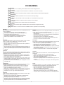 3
3
-
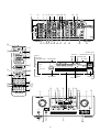 4
4
-
 5
5
-
 6
6
-
 7
7
-
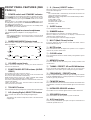 8
8
-
 9
9
-
 10
10
-
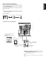 11
11
-
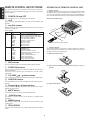 12
12
-
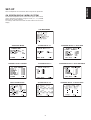 13
13
-
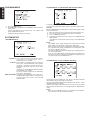 14
14
-
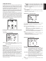 15
15
-
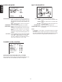 16
16
-
 17
17
-
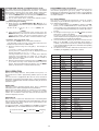 18
18
-
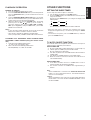 19
19
-
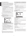 20
20
-
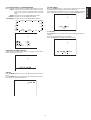 21
21
-
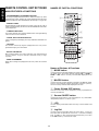 22
22
-
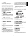 23
23
-
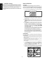 24
24
-
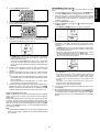 25
25
-
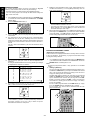 26
26
-
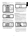 27
27
-
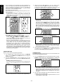 28
28
-
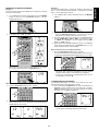 29
29
-
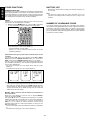 30
30
-
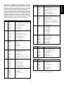 31
31
-
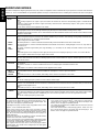 32
32
-
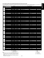 33
33
-
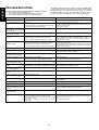 34
34
-
 35
35
-
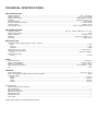 36
36
-
 37
37


Marantz SR 7200 Manuale utente
- Categoria
- Ricevitori AV
- Tipo
- Manuale utente
in altre lingue
- English: Marantz SR 7200 User manual
Documenti correlati
Altri documenti
-
Yamaha AV-75PRO Manuale del proprietario
-
Philips RD0945T Manuale utente
-
-
-
-
-
LD Systems CURV500IAMP 4-Channel Installation Amplifier Manuale utente
-
Dcm Power Time Window Surroundscape Manuale del proprietario
-
-