Eneo MPC-54A0003M0A Quick Installation Manual
- Tipo
- Quick Installation Manual

EN
DE
FR
IT
Quick Installation Guide
1/2.9” HD Camera, 2560x1440,
Day&Night, AF Zoom, WDR,
3.2-9 mm, Indoor
MPC-54A0003M0A

2
Table of content
Parts supplied ...............................................................................................................5
Part names .....................................................................................................................6
Operating instructions .................................................................................................8
Power Supply connections ............................................................................................................................................8
Using OSD controller........................................................................................................................................................8
Description of the OSD control operation ........................................................................................................8
Description of the Motorized ZOOM&FOCUS adjustment .........................................................................8
OSD menu table.................................................................................................................................................................9
Further information ....................................................................................................10

3
EN
Safety instructions
General safety instructions
•
• Keep the operating instructions in a safe place for later use.
• Installation, commissioning and maintenance of the system may only be carried out by authorised
individuals and in accordance with the installation instructions - ensuring that all applicable standards and
guidelines are followed.
• Protect the devices from water penetration and humidity, since these can cause lasting damage.
• Should moisture nevertheless enter the system, under no circumstance switch on the devices under these
conditions, instead send them for examination to an authorised specialist workshop.
•
• The device must be protected from excesses of heat, dust, humidity and vibration.
• When separating the system from the voltage supply, only ever use the plug to pull out the cable. Never
pull directly on the cable itself.
• Lay the connecting cables carefully and check that they are not mechanically stressed, kinked or damaged
and that no humidity can penetrate into them.
• In the event of a malfunction, please inform your supplier.
• Maintenance and repairs may only be carried out by authorised specialist personnel.
• The system must be isolated from the power supply before opening the housing.
•
warranty claim.
• Connection cables should always be exchanged through Videor E. Hartig GmbH.
• Use only original spare parts and accessories from Videor E. Hartig GmbH.
• The housing should only be cleaned using a mild domestic cleaning agent. Never use solvents or petrol as
these can permanently damage the surface.
• During installation, it is essential to ensure that the seals provided are correctly installed and that they are
not displaced during installation. Damaged seals must not be installed and will invalidate any warranty.
• The installer is responsible for the maintenance of the enclosure as per the technical data, e.g. by sealing
the cable outlets with silicone.
•
• The devices may only be operated in the temperature range indicated in the data sheet and within the
• The camera may never be pointed directly at the Sun with the aperture open (this will destroy the sensor).
• It is unavoidable that during manufacture and to a certain extent during later use, humidity will be present
may condense inside the housing.
• To avoid this condensation inside the very tightly sealed housing, the manufacturer has inserted silica gel
sachets in the housing of the various camera types.
• It is however a physical given, that these silica gel bags will reach saturation after a certain amount of time.
They should therefore be replaced with new silica gel sachets.
• During installation, it is essential to ensure that the seals provided are correctly installed and that they are
not displaced during installation. Damaged seals must not be installed and will invalidate any warranty.
• A multipolar, easily accessible isolation device should be installed in the proximity of the IR Spotlight, in
order to disconnect the device from the power supply for service work.
• The earth connection must be made according to the low impedance requirement of DIN VDE 0100.
• Subsequent painting of the equipment surface can impair the function.
• Any warranty claim is invalidated by subsequent painting.
• A safety margin of > 1m from the spotlight must be maintained when viewing directly into the IR Spotlight
in a darkened environment.
• Do not look directly at invisible LED radiation using optical instruments (e.g. a reading glass, magnifying
glass or microscope), since this can endanger the eyes, LED Class 1M.
• Operation of the IR spotlight with a defective cover or during repair is prohibited.

4
Class A device note
This is a Class A device. This device can cause malfunctions in the living area; in such an event, the operator may
need to take appropriate measures to compensate for these.
WEEE (Waste Electronical & Electronic Equipment)
Correct Disposal of This Product (Applicable in the European Union and other European countries with separate
collection systems).
This marking shown on the product or its literature, indicates that it should not be disposed with
other household wastes at the end of its working life. To prevent possible harm to the environment
or human health from uncontrolled waste disposal, please separate this from other types of wastes
and recycle it responsibly to promote the sustainable reuse of material resources. Household users
should contact either the retailer where they purchased this product, or their local government
Business users should contact their supplier and check the terms and conditions of the purchase
contract. This product should not be mixed with other commercial wastes for disposal.
Graphical symbols
Please pay attention to the safety instructions, and carefully read through this instruction guide before initial
operation.
Important points of warning are marked with a caution symbol.
i
Important points of advice are marked with a notice symbol.

5
EN
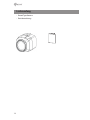
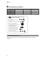
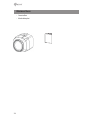
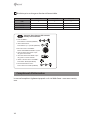
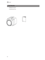
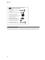
Parts supplied
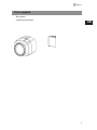
• Box camera
• Operating instructions

6
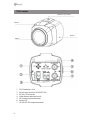
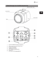
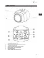
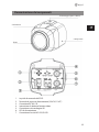
Part names
1. OSD Control joy stick
2. Power input terminal (AC24V/DC12V)
3. RS-485 / IR connector
4. Video format selection Switch
5. HD-Analog output connector
6. Power LED
7. HD-SDI/EX-SDI output connector
Mount Holes (Top / Bottom)
Rear Case
Front Case
Window
PIN 1
Part names
1. OSD Control joy stick
2. Power input terminal (AC24V/DC12V)
3. RS-485 / IR connector
4. Video format selection Switch
5. HD-Analog output connector
6. Power LED
7. HD-SDI/EX-SDI output connector
Mount Holes (Top / Bottom)
Rear Case
Front Case
Window

7
EN
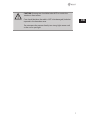
CAUTION: Extreme care should be taken NOT to scratch the
window in front of lens.
Care should be taken the cable is NOT to be damaged, kinked or
exposed in the hazardous area.
Do not expose the camera directly to a strong light source such
as the sun or spot light.

8
Operating instructions
Power Supply connections
Camera can work with either 24VAC or 12VDC, dual voltage power. Primary and second-
ary grounds are completely isolated to avoid the possible ground-loop problems.
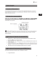
Using OSD controller
Setup menu can be accessed and controlled by OSD control joystick on the rear of the
camera unit. Five commands are available with the joystick.
i
HD-SDI or EX-SDI is selectable by Video format switch only. TVI mode or AHD mode is
selectable in the menu only. (SYSTEM> ANALOG MODE)
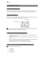
Description of the OSD control operation
1. SET Key ( ) : Access to the menu or enter the setting. To enter the main menu,
press the Set Key down.
2. UP/DOWN Key (
/ ) : Choose the desired sub-menu and to move the cursor up or
down.
3. LEFT/RIGHT Key (
/ ) : Set up the value of the selected menu. Used to adjust the
desired menu selection and to move the cursor left or right.
4. ‘
’ denotes the long press down straightly for about 2 seconds
Description of the Motorized ZOOM&FOCUS adjustment
Works only when OSD Menu is inactive.
1.
: Zoom In
2.
: Zoom Out
3.
: Focus Near
4.
: Focus Far
OSD Control Joy Stick
Video format Switch
i

9
EN
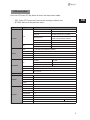
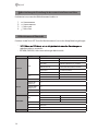
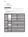
OSD menu table
Press the ‘OSD menu SET key’ down to access the setup menu mode.
• EXIT : Enters ‘EXIT’ menu with save current setting or without save.
• RETURN : Returns to the previous menu.
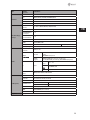
MENU SUB MENU CONFIGURATION
ZOOM/FOCUS
ZOOM
ZOOM SPEED SLOW, MID, FAST
POI ZOOM H/V-POINTER
PRESET ZOOM ZONE NUM, ZONE VIEW, H/V POS, ZOOM RATIO
SMART MOTION ZOOM
ZONE NUM, WINDOW USE, MOTION WIN SET, H/V
POINTER, ZOOM RATIO, DURATION, SENSITIVITY
HOME POSITION O-ZOOM RATIO, DURATION
RATIO DISP OFF, ON
FOCUS
FOCUS MODE ZOOM PUSH, AUTO, MANUAL
LENS INIT. ON
EXPOSURE
MODE AUTO, IRIS PRIOR, SHUT PRIOR, MANUAL, FLICKERLESS
BRIGHTNESS DAY 0~20
BRIGHTNESS NIGHT 0~20
SENS-UP OFF, x2, x4, x8, x16, x32
AGC 0~10
SCENE ENHANCE
WDR
MODE MODE DOL, FRAME
ROI MODE WINDOW ZONE/USE, H/V-POS, H/V-SIZE
WEIGHT LOW, MIDDLE, HIGH
NORMAL
HLC LEVEL, COLOR
BLC H/V-POS, H/V-SIZE
3D-NR OFF, LOW, MIDDLE, HIGH
DAY & NIGHT
EXTERN SMART IR, ANTI-SAT., DELAY, IR LED CTL
AUTO SMART IR, ANTI-SAT., AGC THRES, AGC MARGIN, DELAY
COLOR
COLOR DN
B&W SMART IR, ANTI-SAT.
PICT. ADJUST
WHITE BAL. AUTO, AUTOext, PRESET, MANUAL (C-TEMP, R/B-GAIN)
SHARPNESS 0~10
COLOR GAIN DAY 0~20
COLOR GAIN NIGHT 0~20
GAMMA 0.45, 0.55, 0.65, 0.75
D-WDR OFF, LOW, MIDDLE, HIGH
DEFOG OFF, ON MODE, LEVEL
SHADING OFF, ON

10
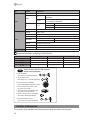
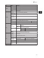
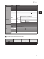
MENU SUB MENU CONFIGURATION
SPECIAL
MIRROR / FLIP OFF, HV, Hor., Ver.
PRIVACY
BOX
ZONE NUM, ZONE DISP, H/V-POS, H/V-SIZE, MASK COLOR,
TRANSPARENCY
POLYGON
ZONE NUM, ZONE DISP, POS 0-X/Y, POS 1-X/Y, POS 2-X/Y,
POS 3-X/Y, MASK COLOR, TRANSPARENCY
DIS OFF, ON
RANGE 10% ~ 30%
FILTER LOW, MIDDLE, HIGH
AUTO-C OFF, HALF, FULL
CAM TITLE OFF, RIGHT UP, LEFT DOWN
SYSTEM
TV SYSTEM EU(PAL), US(NTSC)
RESOLUTION 1440 30P/25P, 1080 30P/25P, 720 30P/25P
SDI MODE HD-SDI, EX-SDI 1.0, EX-SDI 2.0, OFF
ANALOG MODE
TVI MODE UTC TYPE (PELCO-C, HIK-C), HD ANALOG GAIN
HD ANALOG GAIN
AHD MODE
LANGUAGE ENG, CHN(S), CHN, JPN, KOR, GER
COMM. CAM ID, BAUDRATE
RESET ON
EXIT SAVE, CANCEL
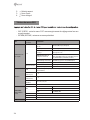
i
Supported resolution according to Video format.
1440P (30/25P) 1080P (30/25P) 720P (30/25P)
EX-SDI * * *
HD-SDI * *
AHD mode * *
TVI mode * * *
● Move the cursor in the MENU :
Moves UP/DOWN/LEFT/RIGHT Joy stick
● Enter the MENU :
Press buttons 9+5+PSET (PRESET)
● Select or Choose value in the MENU :
Press button OPEN (IRIS OPEN)
● Set the Preset Zoom :
Press buttons 1(or ~4)+PSET (PRESET)
● Exit the Preset Zoom mode :
Press buttons 3+4+PSET (PRESET)
TIP
Setting for Zoom Function PTZ Controller
Default protocol PELCO-D
1
43
● Zoom IN: Press button TELE or Spin
the joystick to clockwise.
● Zoom OUT: Press button WIDE or Spin
the joystick to counter-clockwise.
Further information
The manual is also available from the eneo web site at www.eneo-security.com.

11
DE
Inhaltsverzeichnis
Lieferumfang ...............................................................................................................14
Bezeichnungen von Gerätekomponenten ...............................................................15
Betriebsanleitung .......................................................................................................17
Stromversorgungsanschlüsse .................................................................................................................................... 17
Bildschirmmenü-Steuerung verwenden ............................................................................................................... 17
Beschreibung der Bedienung der Bildschirmsteuerung .......................................................................... 17
Beschreibung der Einstellung für das motorisierte Zoom und Fokus ................................................. 18
Bildschirmmenü-Übersicht ......................................................................................................................................... 18
Weitere Informationen ...............................................................................................20

12
Sicherheitsanweisungen
Sicherheitshinweise allgemein
• Bevor Sie das System anschließen und in Betrieb nehmen, lesen Sie zuerst diese Sicherheitshinweise und
die Betriebsanleitung.
• Bewahren Sie die Betriebsanleitung sorgfältig zur späteren Verwendung auf.
• Montage, Inbetriebnahme und Wartung des Systems darf nur durch dafür autorisierte Personen vorgenom-
men und entsprechend den Installationsanweisungen - unter Beachtung aller mitgeltenden Normen und
Richtlinien - durchgeführt werden.
• Die Geräte gegen Eindringen von Wasser und Feuchtigkeit schützen, dies kann zu dauerhaften Schäden
führen.
• Sollte dennoch Feuchtigkeit eingedrungen sein, die Geräte nie unter diesen Bedingungen einschalten,
sondern zur Überprüfung an eine autorisierte Fachwerkstatt geben.
• Das System darf nie außerhalb der technischen Daten benutzt werden, da es zerstört werden kann.
• Das Gerät ist vor großer Hitze, Staub, Feuchtigkeit und Vibrationseinwirkung zu schützen.
• Um das System von der Versorgungsspannung zu trennen, ziehen Sie das Kabel nur am Stecker heraus.
Ziehen Sie nie direkt am Kabel.
• Verlegen Sie die Verbindungskabel sorgfältig und stellen Sie sicher, dass die Kabel nicht mechanisch bean-
sprucht, geknickt oder beschädigt werden und keine Feuchtigkeit eindringen kann.
• Falls Funktionsstörungen auftreten, benachrichtigen Sie bitte Ihren Lieferanten.
•
Wartung und Reparaturen dürfen nur von autorisiertem Fachpersonal ausgeführt werden.
•
•
Garantieanspruch.
• Anschlusskabel sollten immer nur durch VIDEOR E. Hartig GmbH ausgetauscht werden.
• Verwenden Sie nur Originalersatzteile und Original-Zubehör von VIDEOR E. Hartig GmbH.
• Zur Reinigung der Gehäuse immer nur ein mildes Haushaltsmittel verwenden. Niemals Verdünner oder
• Bei der Montage muss grundsätzlich darauf geachtet werden, dass vorhandene Dichtungen ordnungs-
gemäß eingesetzt und bei der Montage nicht verschoben werden. Beschädigte Dichtungen dürfen nicht
mehr verbaut werden und führen zum Erlöschen des Garantieanspruchs.
•
Abdichtung des Kabelaustritts mit Silikon.
•
• Die Geräte dürfen nur in den im Datenblatt angegebenen Temperatur- und Luftfeuchtigkeitsbereichen
betrieben werden.
•
Sensor).
• Es lässt sich nicht vermeiden, dass im Rahmen der Fertigung und auch beim späteren Gebrauch in gewis-
sem Umfang Feuchtigkeit der Umgebungsluft im Gehäuse vorhanden ist. Bei starken Temperaturschwan-
kungen kann sich die Feuchtigkeit im Gehäuse niederschlagen.
• Um dies in dem sehr dicht abschließenden Gehäuse zu vermeiden, hat der Hersteller bei verschiedenen
Kameratypen Silicagel-Beutel in das Kameragehäuse eingelegt.
• Es ist eine physikalische Gegebenheit, dass diese Silicagel-Beutel nach einer gewissen Zeit eine Sättigung
erreichen. Sie sollten deshalb gegen neue Silicagel-Beutel ausgetauscht werden.
• Bei der Montage muss grundsätzlich darauf geachtet werden, dass vorhandene Dichtungen ordnungs-
gemäß eingesetzt und bei der Montage nicht verschoben werden. Beschädigte Dichtungen dürfen nicht
mehr verbaut werden und führen zum Erlöschen des Garantieanspruchs.
• In der Nähe des IR-Scheinwerfers ist eine mehrpolige, leicht zugängliche Trennvorrichtung zu installieren,
um das Gerät bei Servicearbeiten frei schalten zu können.
• Die Schutzleiterverbindung muss nach DIN VDE 0100 entsprechend niederohmig ausgeführt werden.
•
• Durch das Nachlackieren erlischt jeglicher Gewährleistungsanspruch.

13
DE
• Bei abgedunkelter Umgebung und direktem Blick in den IR-Scheinwerfer ist ein Sicherheitsabstand von > 1
m zum Scheinwerfer einzuhalten.
• Unsichtbare LED Strahlung nicht direkt mit optischen Instrumenten (z.B. Lupe, Vergrößerungsglas oder
Mikroskop) betrachten, da dies Augen gefährden kann, LED Klasse 1M.
• Der Betrieb des IR-Scheinwerfers bei defekter Abdeckung oder bei Reparatur ist untersagt.
Hinweis für Geräte der Klasse A
Dies ist ein Gerät der Klasse A. Dieses Gerät kann im Wohnbereich Funktionsstörungen verursachen; in diesem Fall
kann vom Betreiber verlangt werden, angemessene Maßnahmen durchzuführen und dafür aufzukommen.
WEEE-Richtlinie (Elektro- und Elektronik-Altgeräte)
Ordnungsgemäße Entsorgung dieses Produkts (Gilt für die Europäische Union und die anderen Europäischen
Länder mit getrennten Sammelsystemen)
Dieses am Produkt oder in seiner Dokumentation gezeigte Symbol bedeutet, dass es am Ende
seiner Lebensdauer nicht mit dem Hausmüll entsorgt werden darf. Um eventuelle Umwelt- oder
Gesundheitsschäden durch unkontrollierte Abfallbeseitigung zu verhindern, dieses Gerät von
anderen Abfallarten trennen und ordnungsgemäß recyceln, um die nachhaltige Wiederverwen-
dung materieller Ressourcen zu fördern. Haushaltsanwender sollten entweder den Händler, bei
dem sie dieses Produkt gekauft haben, oder ihr örtliches Regierungsbüro kontaktieren, um
Einzelheiten darüber zu erfahren, wo und wie sie dieses Gerät umweltgerecht recyceln können.
Geschäftliche Anwender sollten sich an ihren Lieferanten wenden und die Bedingungen des
Kaufvertrags überprüfen. Dieses Produkt darf zur Entsorgung nicht mit anderen Unternehmensabfällen vermischt
werden.
Bitte beachten Sie die Sicherheitshinweise und lesen Sie diese Anleitung vor Inbetriebnahme sorgfältig durch.
Wichtige Warnhinweise sind mit einem Achtung-Symbol gekennzeichnet.
i
Wichtige Hinweise sind mit einem Hinweis-Symbol gekennzeichnet.

14
Lieferumfang
• Boxed Type Kamera
• Betriebsanleitung

15
DE
Bezeichnungen von Gerätekomponenten
1. Joystick zur Bildschirmmenü-Steuerung
2. Power input terminal (AC24V/DC12V)
3. RS-485 / IR Anschluss
4. Videoformat-Schalter
5. HD-Analog Ausgangsbuchse
6. Power LED
7. HD-SDI/EX-SDI Ausgangsbuchse
Montagelöcher (Oben / Unten)
Hinteres Gehäuse
Vorderes Gehäuse
Fenster
PIN 1

16
ACHTUNG: Achten Sie besonders darauf, das Fenster vor dem
Objektiv NICHT zu verkratzen.
Es muss sorgfältig darauf geachtet werden, das Kabel NICHT zu
beschädigen, zu knicken oder Gefahrenbereichen auszusetzen.
Setzen Sie die Kamera nie direkt einer starken Lichtquelle wie der
Sonne oder einem Scheinwerfer aus.

17
DE
Betriebsanleitung
Stromversorgungsanschlüsse
-
versorgung). Primäre und sekundäre Masse sind vollständig voneinander isoliert, um
mögliche Probleme durch Erdungsschleifen zu vermeiden.
Bildschirmmenü-Steuerung verwenden
hinteren Teil der Kamera erfolgen. Fünf Befehle stehen mit dem Joystick zur Verfügung.
i
HD-SDI oder EX-SDI kann nur über den Videoformat-Schalter ausgewählt werden. Der
TVI- oder AHD-Modus ist nur im Menü auswählbar. (SYSTEM> ANALOG MODE)
Beschreibung der Bedienung der Bildschirmsteuerung
1. SET-Taste ( ): Zum Zugreifen auf das Menü oder Eingeben der Einstellung. Um in
das Hauptmenü zu gelangen, drücken Sie die Set-Taste.
2. UP/DOWN-Taste (
/ ): Zum Wählen des gewünschten Untermenüs und zum
Bewegen des Cursors nach oben oder nach unten.
3. LEFT/RIGHT-Taste (
/ ): Zum Anpassen eines Werts im ausgewählten Menü. Dient
zum Auswahl eines gewünschten Menü-Elements und um den Cursor nach links
oder rechts zu bewegen.
4. ‘
’ bedeutet ca. 2 Sekunden lang gedrückt halten
Joystick zur
Bildschirmmenü-Steuerung
Videoformat-Schalter

18
Beschreibung der Einstellung für das motorisierte Zoom und Fokus
Funktioniert nur, wenn das Bildschirmmenü inaktiv ist.
1.
: Heranzoomen
2.
: Herauszoomen
3.
: Fokus nah
4.
: Fokus fern
Bildschirmmenü-Übersicht
Drücken Sie die Taste ‘SET-Taste für Bildschirmmenü’, um in das Setup-Menü zu gelangen.
•
speichern oder zu verwerfen.
• RETURN (ZURÜCK): Kehrt zum vorherigen Menü zurück.
MENÜ SUB MENU CONFIGURATION
ZOOM/FOCUS
ZOOM
ZOOM SPEED SLOW (langsam) / MID (mittel) / FAST (schnell)
POI ZOOM H/V-POINTER
PRESET ZOOM ZONE NUM, ZONE VIEW, H/V POS, ZOOM RATIO
SMART MOTION ZOOM
ZONE NUM, WINDOW USE, MOTION WIN SET, H/V
POINTER, ZOOM RATIO, DURATION, SENSITIVITY
HOME POSITION O-ZOOM RATIO, DURATION
RATIO DISP OFF (AUS), ON (EIN)
FOCUS
FOCUS MODE (FOKUSSIERUNGSMODUS) ZOOM PUSH, AUTO, MANUAL
LENS INIT. EIN
EXPOSURE
MODUS AUTO, IRIS PRIOR, SHUT PRIOR, MANUAL, FLICKERLESS
BRIGHTNESS DAY
(Helligkeit Tag)
0-20
BRIGHTNESS NIGHT
(Helligkeit Nacht)
0-20
SENS-UP AUS, x2, x4, x8, x16, x32
AGC 0-10
SCENE ENHANCE
WDR
MODE MODE DOL, FRAME
ROI MODE WINDOW ZONE/USE, H/V-POS, H/V-SIZE
GEWICHTUNG LOW, MIDDLE, HIGH
NORMAL
HLC LEVEL, COLOR
BLC H/V-POS, H/V-SIZE
3D-NR OFF (AUS), LOW (NIEDRIG), MIDDLE (MITTEL), HIGH (HOCH)

19
DE
MENÜ SUB MENU CONFIGURATION
TAG/NACHT
EXTERN SMART IR, ANTI-SAT., DELAY, IR LED CTL
AUTO SMART IR, ANTI-SAT., AGC THRES, AGC MARGIN, DELAY
COLOR (Farbe)
COLOR DN (Farb T/N)
B&W (S/W) SMART IR, ANTI-SAT.
PICT. ADJUST
WHITE BAL
(Weißabgleich)
AUTO, AUTOext, PRESET, MANUAL (C-TEMP, R/B-GAIN)
SHARPNESS (Schärfe) 0-10
COLOR GAIN DAY (Farb-
verstärkung Tag)
0-20
COLOR GAIN NIGHT
(Farbverstärkung
Nacht)
0-20
GAMMA 0,45, 0,55, 0,65, 0,75
D-WDR OFF (AUS), LOW (NIEDRIG), MIDDLE (MITTEL), HIGH (HOCH)
DEFOG OFF (AUS), ON (EIN) MODE, LEVEL
SHADING OFF (AUS), ON (EIN)
SPECIAL
MIRROR / FLIP OFF, HV, Hor., Ver.
PRIVACY
(BEREICHSMASKE)
BOX
ZONE NUM, ZONE DISP, H/V-POS, H/V-SIZE, MASK COLOR,
TRANSPARENCY
POLYGON
ZONE NUM, ZONE DISP, POS 0-X/Y, POS 1-X/Y, POS 2-X/Y,
POS 3-X/Y, MASK COLOR, TRANSPARENCY
DIS
OFF (AUS), ON
(EIN)
RANGE (Bereich) 10% ~ 30%
FILTER LOW, MIDDLE, HIGH
AUTO-C OFF, HALF, FULL
CAM TITLE
(KAMERATITEL)
OFF (AUS), RIGHT UP (RECHTS OBEN), LEFT DOWN (LINKS UNTEN)
SYSTEM
TV SYSTEM
(TV-SYSTEM)
EU(PAL), US(NTSC)
RESOLUTION
(AUFLÖSUNG)
1440 30P/25P, 1080 30P/25P, 720 30P/25P
SDI MODE (SDI-Modus) HD-SDI, EX-SDI 1.0, EX-SDI 2.0, OFF (AUS)
ANALOG MODE
(Analog-Modus)
TVI MODE (TVI-MODUS)
AHD MODE (AHD-MODUS)
LANG
UA
GE (SPRACHE) ENG, CHN(S), CHN, JPN, KOR, GER
COMM. CAM ID, BAUDRATE
RESET (WERKSEINSTEL-
LUNGEN)
EIN
EXIT SAVE (SPEICHERN), CANCEL (ABBRECHEN)
UTC TYPE (PELCO-C, HIK-C), HD ANALOG GAIN
HD ANALOG GAIN

20
i
1440P (30/25P) 1080P (30/25P) 720P (30/25P)
EX-SDI * * *
HD-SDI * *
AHD mode * *
TVI mode * * *
Weitere Informationen
Dieses Handbuch ist auch auf der eneo-Webseite unter www.eneo-security.com
verfügbar.
● Move the cursor in the MENU :
Moves UP/DOWN/LEFT/RIGHT Joy stick
● Enter the MENU :
Press buttons 9+5+PSET (PRESET)
● Select or Choose value in the MENU :
Press button OPEN (IRIS OPEN)
● Set the Preset Zoom :
Press buttons 1(or ~4)+PSET (PRESET)
● Exit the Preset Zoom mode :
Press buttons 3+4+PSET (PRESET)
TIP
Setting for Zoom Function PTZ Controller
Default protocol PELCO-D
1
43
● Zoom IN: Press button TELE or Spin
the joystick to clockwise.
● Zoom OUT: Press button WIDE or Spin
the joystick to counter-clockwise.
La pagina si sta caricando...
La pagina si sta caricando...
La pagina si sta caricando...
La pagina si sta caricando...
La pagina si sta caricando...
La pagina si sta caricando...
La pagina si sta caricando...
La pagina si sta caricando...
La pagina si sta caricando...
La pagina si sta caricando...
La pagina si sta caricando...
La pagina si sta caricando...
La pagina si sta caricando...
La pagina si sta caricando...
La pagina si sta caricando...
La pagina si sta caricando...
La pagina si sta caricando...
La pagina si sta caricando...
La pagina si sta caricando...
La pagina si sta caricando...
La pagina si sta caricando...
La pagina si sta caricando...
La pagina si sta caricando...
La pagina si sta caricando...
-
 1
1
-
 2
2
-
 3
3
-
 4
4
-
 5
5
-
 6
6
-
 7
7
-
 8
8
-
 9
9
-
 10
10
-
 11
11
-
 12
12
-
 13
13
-
 14
14
-
 15
15
-
 16
16
-
 17
17
-
 18
18
-
 19
19
-
 20
20
-
 21
21
-
 22
22
-
 23
23
-
 24
24
-
 25
25
-
 26
26
-
 27
27
-
 28
28
-
 29
29
-
 30
30
-
 31
31
-
 32
32
-
 33
33
-
 34
34
-
 35
35
-
 36
36
-
 37
37
-
 38
38
-
 39
39
-
 40
40
-
 41
41
-
 42
42
-
 43
43
-
 44
44


Eneo MPC-54A0003M0A Quick Installation Manual
- Tipo
- Quick Installation Manual
in altre lingue
- English: Eneo MPC-54A0003M0A
- français: Eneo MPC-54A0003M0A
- Deutsch: Eneo MPC-54A0003M0A
Documenti correlati
-
Eneo MPD-74A0003M0A Quick Installation Manual
-
-
-
-
-
-
-
-
-
Altri documenti
-
CAME XTBV1267 Guida d'installazione
-
-
-
CNB A2363NL/A2363PL Manuale del proprietario
-
Elvox 46516.212 Istruzioni per l'uso
-
Clinton Electronics CE-IDX2HDL Guida d'installazione
-
Comelit AHDCAMS05VA Guida Rapida
-
-
Celexon PTZ Videokonferenzkamera VK1080 Full HD Manuale del proprietario
-