ZyXEL Communications ZoneDAS Manuale utente
- Tipo
- Manuale utente


ZoneDAS User Guide Page | 2
IMPORTANT!
READ CAREFULLY BEFORE USE AND
KEEP THIS GUIDE FOR FUTURE REFERENCE.
Every effort has been made to ensure that the information in this manual is accurate.
However, screenshots and graphics in this manual may still differ slightly from what you see
on screen due to differences between release versions and/or computer operating systems.
Related Documentation
• Hardware Installation Guides (BU, RU, and Extender)
The Hardware Installation Guides show how to install the BU (Base Unit), RU (Remote
Unit), and Extender.
• More Information
In the event that a problem cannot be solved through the information in this manual,
you should contact your exclusive distributor. If you cannot contact your distributor,
then contact international customer support at [email protected] and/or
ibs.tech@zyxel.com.tw.

Content Overview
ZoneDAS User Guide Page | 3
Content Overview
Introduction ............................................................................................................................................................................................ 4
First Time Installation ............................................................................................................................................................................. 13
The Web Configurator ......................................................................................................................................................................... 25
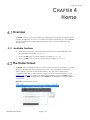
Home ...................................................................................................................................................................................................... 29
Setting ..................................................................................................................................................................................................... 35
Fault ......................................................................................................................................................................................................... 39
System ..................................................................................................................................................................................................... 45
Maintenance ......................................................................................................................................................................................... 51

Chapter 1: Introduction
ZoneDAS User Guide Page | 4
CHAPTER 1
Introduction
Design Overview
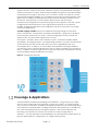
ZoneDAS is a brand-new take on Active DAS architecture, one that is simple, flexible, and
highly functional. Being analogue based, it avoids digital conversion and its inherent signal
delays. Being CAT5 based, it avoids the trouble and cost of deploying coaxial cables and
fiber optics. Being modular, it offers unrivaled flexibility in band configuration, coverage,
and upgradability. Being active, it offers precise, real-time control over output signal
strength and pattern. And being smart… it compensates for cable loss and sets system gain
to match user-defined RF output—all automatically.
Like passive DAS, ZoneDAS begins with signal source(s) from one or more operators. Instead
of having a passive combiner that merges signals and sends them to passive antennas,
however, it has a Base Unit (BU) that replaces the combiner, and Remote Units (RUs) that
replace the passive antennas. And whereas passive architecture is a complex series of
compromises around limited signal strength and delicate antenna output, ZoneDAS
architecture replicates signal strength and guarantees full-strength antenna output. This
allows for a far simpler, goal-oriented design: simply place an RU wherever signal is required
and know that it will have high quality signal! After all, CAT5 cabling goes anywhere.
Basic layout looks like this: up to 4 input signals come through RF coaxial cables and plug
into the BU, which often sits in the machine room along with telephone and networking
equipment. The BU then processes these signals and sends them via CAT5 cable to its RUs (1
per cable), which are placed throughout the building to broadcast the signals. Each CAT5
cable can be up to 100 meters long, and the whole system requires just one power plug, for
the BU. RUs get power over Ethernet and do not require additional power. That’s it! As
simple as Active DAS can be.
Figure 1 Basic ZoneDAS Architecture

Chapter 1: Introduction
ZoneDAS User Guide Page | 5
Like the combiner in passive DAS, the BU combines its input signals and sends the combined
signal to each RU. Unlike in passive DAS, cable loss has been compensated for and signal
quality is preserved for every RU. Each RU simply amplifies the signal to its specified strength
and broadcasts it through its antenna(s), up to 4 of which it may fit onto each RU. The RU
has powerful integrated amplifiers (up to 23 dBm per band) and uncompromised low noise
figures (down to 5dB) for optimizing system footprint and thus lowering overall TCO of the
site solution. With ZoneDAS, you can software select between directional and
omnidirectional configurations for optimal coverage and best signal-to-noise ratio. For RUs
configured with external antennas, output signal pattern depends on the antennas
installed. Strategic RU placement and configuration will then ensure optimum coverage
and strong cellular signal.
ZoneDAS is highly scalable and supports additional coverage through its companion
device, the Extender. An Extender is essentially a subsidiary BU: it plugs into the BU like an
RU and supports a brand-new set of RUs. It receives RF signal from the BU, transmits the
signal to its RUs, and sends its RUs' signals back to the BU.
In this guide, “ZoneDAS” refers to the entire BU-RU system. ZoneDAS is capable, flexible,
expandable, and elegantly simple. Its modular design enables it to support operator bands
and frequencies from around the world and ensure future upgradability when new
technologies arrive. Its ability to use CAT5 cables and PoE/RFoE technologies facilitates
cost-effective, quick, and simple deployment, with no need for separate power supplies for
its RUs. In addition, its simple, single-wire RU connections mean easy re-deployments should
the host building undergo modifications to its layout.
Figure 2 ZoneDAS with Extender
Coverage & Applications
ZoneDAS is ideal for medium sized buildings and installations. Its BU connects up to 8 RUs,
each of which supplies cell phone signals for an area up to 2,500m
2
, so a basic ZoneDAS
setup covers up to 20,000m
2
. ZoneDAS is also highly extensible and can service larger areas
when required, through Extenders. Installing an Extender adds capacity for 1~8 additional
RUs, further increasing maximum coverage by 20,000m
2
. With a full complement of 8
Extenders, one ZoneDAS can connect up to 64 RUs for a total coverage area of
160,000m
2
— the area equivalent of 3 football fields! This could represent multiple floors in a
high-rise office/residence, a large factory, or a large shopping center.

Chapter 1: Introduction
ZoneDAS User Guide Page | 6
Hardware Overview
Before installation, it is helpful to go over the system’s parts and what this User Guide calls
them. In particular, one needs to be familiar with the ports and modules on the BU,
Extender, and RU. This section describes these devices’ front panels and provides
information that may require special attention. Where “left” and “right” are mentioned, this
Guide assumes that the user is sitting opposite to and looking at the front panel of the
device.
1.3.1 Names and Terminology
ZoneDAS devices use a 2-letter naming scheme. Each device is abbreviated into 2 letters.
For example, the Base Unit (a device) is abbreviated into just “BU”. Below is a short list of 2
letter device abbreviations and what they represent:
BU
Base Unit
RU
Remote Unit
ET Extender
Major ports and modules are also abbreviated into 2 letters. A Radio Frequency module, for
example, is referred to as an “RF” module. Likewise, the slot for inserting that module is
called the “RF” slot, and the port on that module is referred to as the “RF” port. Below is a
short list of 2 letter port/module abbreviations and what they represent:
RF Radio Frequency port / slot / module
SD
Signal Distribution port / slot / module
(for connecting ETs and RUs)
MB
Motherboard
As each BU supports up to 4 RF connections and up to 8 RUs through its 4 RF modules and 2
SD modules (4 SD ports on each), a third character is added to differentiate each RF or SD
module/port. Below is a summary of such differentiation:
RFA ~ RFD Left-most RF module/slot/port is A, right-most is D, etc.
SD-U, SD-L
SD-U is the “upper” SD module/slot,
SD-L is the “lower” SD module/slot
SD1 ~ SD8
(a.k.a. RU1~RU8)
The left-most SD port on SD-U is SD1, the right-most is SD4.
The left-most SD port on SD-L is SD5, the right-most is SD8.
But on the SD module front panel, they are labelled RU1~RU8
instead of SD1~SD8.
ET5
The Extender that’s connected to SD5 on the BU.
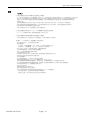
Finally, because ports and modules reside on devices, and because some of the most
important ports and modules actually exist on different ZoneDAS devices, device
abbreviations are placed in front of port/module abbreviations to specify specific ports on
specific devices. The (single) SD port on an RU, for example, is called an RU-SD, while the 5
th
SD port on the BU is called BU-SD5. Below are some examples of combined abbreviations
and what they mean:
BU-RFA
Left-most RF module/slot/port on the BU.
RU2-RFA
The RF module that is installed onto the RF slot “A” on RU2. This
module would match the BU-RFA in terms of Band and frequency.
BU-SD1 The 1
st
SD port on the BU
ET5-SD2
The 2
nd
SD port on the Extender that’s connected to the 5
th
SD port
on the BU.
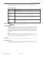
Only the most frequently connected devices and ports have 2-letter abbreviations. For
example, the Fan module has no abbreviation, and words like Power and Alarm have 3-
letter abbreviations.

Chapter 1: Introduction
ZoneDAS User Guide Page | 7
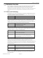
1.3.2 BU (Base Unit)
The Base Unit is the command center for the entire system. Every device on the system is
controlled by or through the Base Unit. To a large degree, the Base Unit’s LED indicators also
reflect the state of the entire system. These LEDs and ports are located on the BU’s Front
Panel. The figure below shows the Front Panel and its different parts.
Figure 3 BU Front Panel
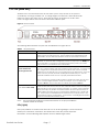
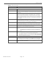
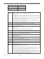
The following table describes the parts that are labelled in the figure above.
Table 1 BU System Parts
SYSTEM PART DESCRIPTION
Fan Module
The BU’s fan module provides active cooling for the entire BU, which can operate
safely for just a few minutes fan free. The fan module is hot-swappable and user
replaceable. See the Hardware Installation Guide for replacement instructions.
BU-MB
The BU’s Motherboard (BU-MB) is the user’s gateway to controlling everything in
ZoneDAS. To access the Web Configurator, connect a computer to the MGMT port
via a CAT5 cable. To access the Command Line Interface (used by the vendor
only), connect it to the Serial Port with a serial cable.
BU-RF (A to D)
A is the left most slot
D is the right most slot
This is where the BU houses its collection of Radio Frequency (RF) modules. Each BU
has 1 to 4 of these modules, and each module provides one RF port.
To connect the
BU to a signal source, install an RF module into an RF slot and connect a coaxial
cable from the module’s RF port to the coaxial outlet at the signal source. The base
station can be a picocell, femtocell, LTE RRU (Remote Radio Unit), etc. See the
Hardware Installation Guide on how to properly install a BU-RF module.
Note: The frequency used by the RF module in each RU must match the one used
by the corresponding RF module in the BU. For example, if you use a Band 1 RF
module for BU-RFA, then you must also use a Band 1 RF module for RU-RFA.
BU-SD
(ports labeled RU1 to RU8)
This is where the BU houses its Signal Distribution (SD) modules. Each BU comes with
one SD module and has room for one other.
Each SD module comes with 4 SD ports,
and each SD port can connect one RU or Extender. To connect an RU or Extender,
simply pick an SD port (install a second SD module if the first is full) and connect a
CAT5e cable from the RU’s SD port (or the Extender’s Extender port) to the BU’s SD
port. The BU supports the IEEE 802.3af PoE standard and can supply power to any
connected RU (only RUs, not Extenders). For instructions on installing BU-SD modules,
please see the Hardware Installation Guide.
Note: See the Hardware Installation Guide for information on the proper installation
of BU-RF and BU-SD modules.
LEDs (Lights)
Most ports/modules on the BU come with their own set of LED signal lights. These include the
MGMT port, each BU-RF, each BU-SD, and the BU-MB. These LEDs provide important
information, and the following table explains what the different lights mean.

Chapter 1: Introduction
ZoneDAS User Guide Page | 8
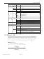
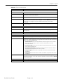
Table 2 BU LEDs
LED COLOR STATUS DESCRIPTION
MGMT port
(Management)
Green
(Left)
Blinking The BU is transmitting or receiving to/from an Ethernet device.
Amber
(Right)
On
The
MGMT
port is connected.
None Off
The
MGMT
port is not connected to a compatible device, or the port is
disabled.
PWR (Power) Green On The BU is powered on and functioning properly.
Off The power is off or the system is malfunctioning / not ready.
ALM (Alarm) Red On
There is a hardware failure, such as device overheat, wrong voltage, or
abnormal fan speed.
Blinking The BU is being reset.
Off The system is functioning normally.
BU-RF Module
PWR (Power) Green On The inserted RF module is powered on.
Blinking Firmware upgrade in progress; do not disconnect power supply.
Off The inserted RF module is not ready.
ALM (Alarm) Red On The system detects an operational error.
Off The inserted RF module is functioning normally.
BU-SD Module
RUx port
Green
(Left)
On An RU is connected to this port and receiving power from the BU.
Blinking An RU is attempting to connect to this port.
Off The connected RU is not powered on.
Amber
(Right)
On
Cable signal loss between the BU and the connected RU has
exceeded the threshold.
Blinking
An RU hardware failure, such as device disconnection, high device
temperature, or abnormal fan speed, is detected.
Off The connected RU is functioning properly.
1.3.3 RU (Remote Unit)
Remote Units are important because they are the active antennas that actually broadcast
the signals that are routed through the BU. Being smart, active devices, they also have LED
indicators on their front panels that show their current condition. These LEDs are divided into
two groups: one reports on the RU-MB; the other reports on the RU-RFs. The figure below
shows the front panel and where the LEDs are located, and the tables that follow will
provide the details.
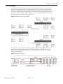
Figure 4 RU Front Panel

Chapter 1: Introduction
ZoneDAS User Guide Page | 9
SD Port
SD Port
RF Slot A
RF Slot D
RF Slot B
RF Slot C
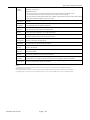
Table 3 RU System Parts
LEDs (Lights)
The following table describes the LED signals on the RU.
Table 4 RU LEDs
LED COLOR STATUS DESCRIPTION
PWR (Power) Green On The system is powered on
Off The DC power is off.
SYS (System) Red On
There is a hardware failure, such as device overheat or abnormal fan
speed.
Off The system is functioning normally.
Cable Red On The cable signal loss currently exceeds the threshold.
Off The signal is below the threshold.
Active Green On The inserted RU-RF module is powered on.
Off The inserted RU-RF module is not ready.
ALM (Alarm) Red On The system detects an operational error.
Off The inserted RU-RF module is functioning normally.
RF Module Placement
Each Remote Unit has an RJ45 port on one side and LED lights on the opposite side. The
following illustration shows where RF modules A, B, C and D are placed in relation to the port
and lights.
Figure 5 Remote Unit RF Modules
SYSTEM PART DESCRIPTION
RU-MB
The RU Motherboard (RU-MB) provides the platform upon which up to 4 RU-RF
modules may reside. Each RU-
RF slot is labelled A, B, C or D, to match the RF slots on
the BU. The system is able to power the RU-MB and each RU-RF independently.
These devices also provide LEDs signals independently. Three LEDs are used to
provide signals for RU-MB. The next table explains what their signals mean.
RU-RF
The RU’s Radio Frequency modules (RU-RF) are the devices that actually broadcast
RF signals to users’ cell phones. Each RU-RF comes with its own antenna (external
antenna models excluded), and each RU has up to four RF modules, referred to as
RU-RFA to RU-RFD. The letter after RU-RF represents the slot in which the RF module is
installed.
Note: The frequency used by the RF module in each RU must match that of the RF
module in the BU. For example, if you use a Band 1 RF module for BU-RFA, then you
must also use a Band 1 RF module for RU-RFA.

Chapter 1: Introduction
ZoneDAS User Guide Page | 10
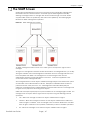
1.3.4 Extender
The Extender is a free-standing add-on unit that can greatly expand both the reach and
capacity of any ZoneDAS system. Whereas an RU takes up one SD port to provide just one
service point, the Extender would take that same SD port and turn it into 8 more! By nature
of being a “mid-point station”, it also provides another 100 meters of reach between the BU
and the RU. So, whereas before there could be a 100-meter cable distance between the
BU and the RU, with an Extender there can be 200.
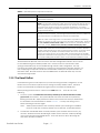
Figure 6 Extender Connection Illustration
The Extender has the same ports and LEDs as the BU, except it has replaced the BU’s 4 RF
modules with a single Extender module. LED indicators and ports are located on its front
panel, with near identical layout as the BU. The figure below shows its front panel and its
different parts and ports.
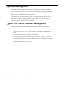
Figure 7 Extender Front Panel

Chapter 1: Introduction
ZoneDAS User Guide Page | 11
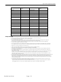
The following table describes the system parts and ports on the Extender:
Table 5 Extender System Components and Ports
SYSTEM PART DESCRIPTION
Fan Module
This is the Extender’s fan module. See the Hardware Installation Guide for
replacement instructions.
ET-MB
This is the Extender’s Motherboard (ET-MB). You may connect your computer to the
MGMT port using an RJ-45 Ethernet cable and access the Extender directly using its
Web Configurator, but this is for special situations only. Likewise, the Serial Port is
used only by the vendor to access the Command Line Interface. For normal
operation, everything is controlled through the BU, which connects to the Extender
though the Extender Port.
Extender Module
The Extender Module houses the Extender Port: the portal through which the
Extender connects to the BU. Connecting a shielded CAT5e (or better) cable from
one of BU’s SD ports to the Extender Port will activate the Extender.
Note: The cable connecting the BU to the Extender is responsible for transferring
signal for up to 8 RUs. As such, we must protect the cable’s signal quality.
Make sure
you use a shielded or foiled CAT5e cable for this connection. This includes STP, FTP,
S/UTP, S/FTP, or S/STP. DO NOT use a plain UTP (unshielded twisted pair) cable.
ET-SD (ports labeled RU1 to
RU8)
This is where the Extender houses its Signal Distribution (SD) modules. As with the BU,
each Extender comes with one SD module and has room for one more. Each SD
module comes with 4 SD ports, each of which connects one RU. To connect an RU,
simply pick an SD port (install a second SD module if there are no more) and
connect it to the RU’s SD port via a CAT5e cable. The Extender supports the IEEE
802.3af PoE standard and can supply power to any connected RU. For instructions
on properly installing ET-SD modules, please see the Hardware Installation Guide.
The Extender looks like a BU and even has its own Web Configurator interface. But it cannot
be controlled through the MGMT port like a BU. Instead, it must be connected to a BU
(through its Extender port) and controlled through the BU’s Web Configurator. The only
function that requires direct MGMT port connection to the Extender is firmware updates. For
that, simply plug a computer console into the Extender’s MGMT port and proceed as if the
Extender is a BU. All other functions are unavailable from the Extender itself; they must be
accessed through the BU.
1.3.5 The Reset Button
If ZoneDAS ever gets stuck and prevents you from accessing the Web Configurator, use the
Reset button on the BU front panel to revert settings to factory-default values. The Reset
button is located inside a small pinhole, right between the MGMT and Serial ports.
Before pressing the Reset button, make sure the PWR LED is on. Then do one of the
following:
1. To set the system’s IP address back to factory defaults, press the Reset button for three
(3) seconds, then release. The system indicates that three seconds have passed by
flashing the ALM LED. Simply release the Reset button at that time and you will find that
the IP address has reverted back to default 192.168.1.1. To keep this setting, save it
before restarting the device again.
Note: Admin password will not reset to factory default upon resetting the IP address.
However, it will reset to factory default with a hard reset, as described below.
2. To hard reset all variables back to factory defaults, press the Reset button for ten (10)
seconds. Whereas the ALM LED will begin to blink at three seconds, it will stop blinking
at ten seconds and automatically reboot. Once the reboot is done, all settings will
have been restored to default.

Chapter 1: Introduction
ZoneDAS User Guide Page | 12
System Management
The primary interface through which ZoneDAS is managed and configured is called the
Web Configurator. It is accessible through any modern web browser and is designed for
easy setup and management. It can be accessed on-site through a single network cable,
elsewhere in the building through VLAN, or across the globe through VPN. Details on using
Web Configurator will be discussed in later chapters.
In addition to Web Configurator, ZoneDAS can be managed via SNMP (Simple Network
Management Protocol) using EMS (Element Management System) or a compatible Network
Management System. This allows ZoneDAS to be managed as part of a large group of
devices—remotely monitored, remotely controlled.
Best Practices for ZoneDAS Management
Once ZoneDAS is deployed, do the following regularly for effective management and
optimal security.
• Change the password. Use a strong password that’s hard to guess and includes
different character types, such as a mix of numbers, symbols, and small and capital
letters.
• Write down the password and place it in a safe location.
• Back up the configuration file and make sure you know how to make a restore with it.
See Section 7.3 for more on dealing with configuration files. Restoring an earlier
functional configuration may be useful if the device becomes unstable and/or crashes.
Compared to re-configuring ZoneDAS from scratch, it is often easier to restore your last
working configuration and go from there.

Chapter 2: First Time Installation
ZoneDAS User Guide Page | 13
CHAPTER 2
First Time Installation
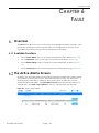
Overview
This chapter takes the user through setting up ZoneDAS for the first time. In addition to
providing step-by-step instructions, it goes through basic system concepts (some of which
are unique to ZoneDAS) and briefly explains many parts of the Web Configurator
(ZoneDAS’s browser interface). For a comprehensive coverage of each Web Configurator
menu item, explaining all the LED lighting codes and selectable items, please refer to the
chapters that follow, starting with Chapter 3.
System Setup
There are two steps to setting up ZoneDAS for the first time: Preparation and Configuration.
Preparation refers to the hardware placement and installation that must be done before
configuration starts. Configuration refers to the software adjustment of settings and
parameters. This section provides a brief overview of each; the next section explains
Configuration in detail.
2.2.1 Preparation
ZoneDAS setup and planning is quick and easy, but it is still prudent to do everything in the
proper order and tick items off a list. Here we provide a list of everything that must be done
before software configuration can begin.
1. Decide where to place the BU and all the RUs.
a. make sure the BU can access source signals from its planned location
b. make sure that each RU will be within a 100-meter cabling distance from the BU
2. Run CAT5e (or higher spec’d) cables from the BU location to each RU location.
3. Physically install the BU and RUs at their planned locations. For this, please see the BU
and RU Hardware Installation Guides.
4. Connect each RU to the BU with the CAT5e cables.
5. Connect each RF signal source to the BU.
a. Before connection, be sure that the RF signal is always below +30dBm (1W).
Anything above 30dBm will permanently damage the BU! The specified
operational range for ZoneDAS is 0 ~ +24 dBm, while the recommended input
signal range is 0 ~ +15 dBm.

Chapter 2: First Time Installation
ZoneDAS User Guide Page | 14
6. As each RF module is band-specific and likely pre-installed, ensure that each signal
source is plugged into the RF module with corresponding frequency range. The 3GPP
band (number) is printed on the RF module front panel. Unlike SD ports, RF ports are not
freely interchangeable.
7. Plug in the BU’s power cord and turn on the BU.
8. Connect a computer to the BU, through the BU’s MGMT port.
9. Open the browser on the computer and go to http://192.168.1.1
.
2.2.2 Configuration
Once all the hardware has been installed, connected, and powered up, configuration may
begin. Please follow the steps below to ensure that everything is properly done.
1. Log into ZoneDAS
2. Set the System Time
3. Ensure that RF inputs are within range (0 ~ 24 dBm)
4. Configure BU parameters
5. Mount each RU
6. Configure RU parameters
7. Turn Service On
a. this will activate System Calibration automatically
b. ensure that system remains error free after System Calibration
8. Fill in descriptive information such as Site Name and Site ID
9. Configure network settings (Syslog Server etc.) for central management
10. Save settings
11. Create Configuration File, and back it up on a computer
Configuration Step by Step
As the Configuration steps outlined in the previous section involves numerous details, this
section will go through each detail to ensure smooth installation.
2.3.1 Log into ZoneDAS
Logging into ZoneDAS is fairly straightforward. Simply connect your computer’s LAN port to
the BU’s MGMT port, then open a browser window (any modern browser will do). In the
Address field, type http://192.168.1.1
and press Enter. The following screen should appear:
Figure 8 ZoneDAS Login Screen

Chapter 2: First Time Installation
ZoneDAS User Guide Page | 15
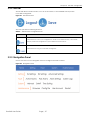
From here, simply enter the Username and Password. Default user name is “admin” and
default Password is “1234”. Once logged in, the Home screen would appear. The following
is a sample Home screen.
Figure 9 ZoneDAS home screen
If you have any problems logging into the Web Configurator, please refer to
Chapter 3.2,
Accessing the Web Configurator, where the process is explained in greater detail.
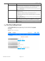
2.3.2 Set System Time
Once logged in, the first thing to do is to set the System Time and Time Zone. This will ensure
that all System Messages (and the Syslog) are stamped with the correct time and date. To
do that, click System on the Navigation Panel (the blue bar) and select Time Settings. You
will see the Time Setting screen, as shown below:
Figure 10 ZoneDAS home screen
If the computer console is set to the ZoneDAS BU’s local time, simple click on Copy from PC
and click Apply (blue button, at bottom). This will update the System Time (shown in
orange, top center) and Time Zone to those of the console and show them under New
Date, New Time, and New Time Zone.
If the computer console is not a suitable source of time information, then set the time and
date manually. Be sure to set the correct Time Zone before setting the time. Simply select
the ZoneDAS BU’s time zone from the New Time Zone drop down menu, noting that UTC is

Chapter 2: First Time Installation
ZoneDAS User Guide Page | 16
effectively the same as GMT. If the area also uses Daylight Saving(s) Time, please click the
Enable checkbox under Daylight Saving Time and set the correct values for Start Time and
End Time. The former indicates when Daylight Saving(s) Time starts every year (in the
Spring); the latter indicates when it ends (in the Fall).
It is possible to set / maintain the system time automatically via an SNTP Time Server. That is
not required at this point, but you may refer to Chapter 7.4 Time Settings Screen
to see how
this can be done.
2.3.3 Ensure that RF Inputs are Within Range (0 ~ 24 dBm)
Having set the System Time, one can move on to configuring the system’s RF inputs. These
come from two sources: directly from the Operator through a BTS / small cell, or off-air
through an Off-Air Kit / SymmRepeater. Either way, the signal will come through a coaxial
RF cable and ZoneDAS will treat all signal the same way.
The important thing is to ensure that the signal strength of each RF input falls within the
system’s operating range of 0 to 24 dBm. ZoneDAS operates optimally when each RF input
signal is between 0 and 15 dBm. It will continue to work properly from 15 to 24 dBm, but
anything less than 0 dBm is too weak for the system to work with and any level over 24 dBm
is too strong for the electronics. If an input signal falls between 24 and 30 dBm, the system
will activate its Protection Mode and shut down all operation for that RF channel (and only
that channel). Input signal stronger than 30 dBm may cause permanent system damage!
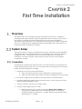
The easiest way to see if an RF input is within range is to look at the Home screen, at the BU.
There, under each RF port, will be an “X”, “”, or “!” mark, like this:
Please note that Module A is the one on the left-most side. Module B is the one to its right,
Module C is the next one on the right, and Module D is the right most module. The
frequency band used by each module is clearly marked on its face plate.
If the strength of RF input for a module falls within the 0 to 15 dBm optimum range, there will
be a check mark (
) under that RF port. If the RF signal is on the strong side, between 15
and 24 dBm, there will be an exclamation mark (
!) to warn of sub-optimal performance. If
the RF signal is too weak, below 0 dBm, there will be an X mark to show “no signal”.
Please ensure that all connected inputs are marked with check marks (
). If not, please
consult the signal source provider, such as the telecom operator, and resolve the issue.
2.3.4 Configure BU Parameters
Once all RF signal sources are verified to be within range, it is time to configure the BU’s
parameters. Specifically, this means RF parameters. If this installation is on behalf of a
telecom operator, simply upload their ready-made config file onto the BU, using the steps
covered in the next section. If not, the following information is required for each RF signal
source:
1. The Frequency Band used by the RF signal (e.g. Band 1, Band 3, Band 7, Band 41,
and so forth).
2. Cellular technology used (choose 2G, 3G, or 4G LTE).
This matters, because it affects the system’s internal parameter settings and tuning
algorithms. However, if the information is unknown, a selection called Auto is also
available.

Chapter 2: First Time Installation
ZoneDAS User Guide Page | 17
3. Center frequency for the RF channel. ZoneDAS operates on 20 MHz-wide channels.
So if the frequency band is from 2140 to 2160 MHz, simply enter 2150 as the center
frequency.
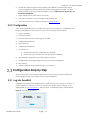
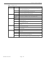
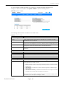
Once the information is ready, simply enter them into the Web Configurator (the system’s
web-based interface). To do that, click Setting on the Navigation Panel (the blue bar) and
select BU Settings. You will then see the BU Setting screen, as shown below:
Figure 11 ZoneDAS BU Settings screen
The gray bar at the top of the table shows RF-A to RF-D, from left to right. These correspond
to RF modules A, B, C and D. Four identical columns lie below each of these labels, and the
first few rows in each column correspond to the information requested above. Note that
the system has detected the Frequency Band for each channel, so only verification is
required. Simply fill in all the rows for each connected channel, using the information on
hand. The system is also equipped with error detection, so frequency values that do not fall
within the detected Frequency Band will not be accepted as valid input.
The only row not yet mentioned is Green Power Down, which dictates whether a channel
will go into Power-Saving Mode if there is no input signal for a time. The unit is hours, so
simply input how many hours the system should wait before switching the channel to Power-
Saving Mode. To disable Power-Saving Mode, simply enter 0 (factory default).
Once everything has been input correctly, click Apply. For verification, go to the BU screen
and check the RF activity graph for each active RF channel to ensure that signal is as
expected. This will be discussed in the section after next.
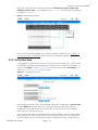
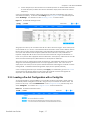
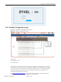
2.3.5 Loading a Pre-Set Configuration with a Config File
As mentioned above, if this installation is on behalf of a telecom operator, simply upload
their ready-made Config file onto the BU, using the steps covered in this section here. The
process is very easy. First, click Maintenance on the Navigation Panel (the blue bar) and
select Config File. You will see the Config File screen, which looks like this:
Figure 12 ZoneDAS Config File screen

Chapter 2: First Time Installation
ZoneDAS User Guide Page | 18
From there, click Restore and locate the target Config file from the browser’s file manager.
Double click on the file once it is found, and ZoneDAS will begin the restoration process,
which typically takes less than 10 seconds. When it is done, you will see “Success” at the
top center of the screen.
Done! Now all the settings have been loaded and, depending on how the Config file was
written, there should be no more setting left to do, and only verification remains to be done.
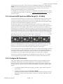
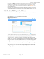
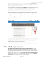
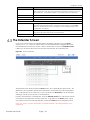
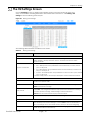
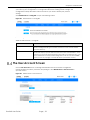
2.3.6 Checking RF Activity from the BU Screen
As mentioned above, it is prudent to go to the BU screen and check the RF activity graph
for each connected RF channel to ensure that signal is as expected. To do this, start by
clicking Home on the Navigation Panel. From there, move the mouse pointer to the black
Base Unit, such that it is encased in blue, as shown below, then click.
Once clicked, the BU screen would appear, as shown below:
Figure 13 ZoneDAS BU screen
The large graph at the bottom of the screen depicts RF activity for the RF module selected.
In the above scenario, it is RF-D. To see RF activity for other RF modules, simply click one of
the four blue buttons near the top center, marked RF-A, RF-B, RF-C, and RF-D.
The graph has 2 lines: one yellow and one blue. The yellow line marks the Source Signal
Strength at any given time, measured against the left axis. The blue line marks the Downlink
System Gain that the system automatically generates at the same time, measured against
the right axis. The bottom axis indicates the time. With the cursor on top of the graph,
turning the scroll wheel on the mouse shrinks or expands the scope of the time axis, while
holding on to the left mouse button and moving the mouse left and right makes the graph
go back and forward in time.
What needs to be done at this point, for all active RF channels, is that the user must click
through all the graphs and check that no input signal ever goes beyond the normal
operating range of 0 to 24 dBm. If they do, there could be a potential problem and the
situation must be reported.

Chapter 2: First Time Installation
ZoneDAS User Guide Page | 19
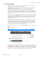
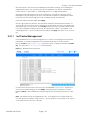
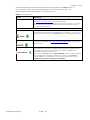
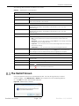
2.3.7 Mount Each RU
With the BU ready for operation, it is time to configure all the RUs. This involves mounting,
adjusting parameters, and calibration. Mounting is first.
Mounting is the process by which the system turns on an RU and registers its connection.
Until it is mounted, an RU is dormant and has no function except self-identification.
Mounting an RU turns on its systems, creates a record for the SD port connection, and
associates the port with the unique characteristics particular to that combination of cable
and RU. After system calibration, this record will also store the connection’s calibration
information, so recalibration will not be required when an RU is unplugged temporarily (e.g.
to hard reset).
Once an RU is mounted, if you plug in a different RU into the same port, ZoneDAS will detect
the difference and display a Mount button beside the newly connected device. Click it for
ZoneDAS to activate the connection to the new RU. As ZoneDAS only remembers one
device per SD port, this will also overwrite the previous record with data from the newly
plugged in RU/Extender.
Mounting is important because it prevents RU confusion. As each SD port is set with its own
output parameters, such as power and pattern, it can be troublesome when an RU gets
unplugged and the user forgets where it was plugged into before. With mounting, the
system would know if an RU was previously plugged into a particular SD port—and would
notify the user, as described above. This helps the user plug each RU back into its place,
save confusion, and prevent time-consuming recalibrations.
To mount RUs, go to the Home screen and find the blue Mount button at each RU’s left side,
like this:
Figure 14 ZoneDAS Mount button
The on-screen line connecting the BU to the RU should be colored gray. This indicates an
unmounted state. Click on Mount and wait for the line to turn yellow. Yellow line means the
device has been correctly mounted. Once mounted, it becomes possible to configure the
RU’s parameters. If all the RUs have been plugged in properly, go ahead and click Mount
for each RU. Once all the lines have turned yellow, proceed to the next section.

Chapter 2: First Time Installation
ZoneDAS User Guide Page | 20
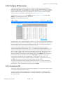
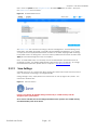
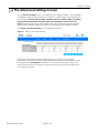
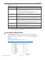
2.3.8 Configure RU Parameters
Once an RU has been mounted, it may be necessary to adjust its output parameters. In
particular, each RU must be configured for a specific output signal strength and a specific
antenna configuration. The default RF output signal strength for RUs is +17 dBm per RF band
module, while the default antenna configuration is “Omni”. If these are not the desired
values for all RUs, it is possible to adjust them from the RU Settings screen.
To reach the RU Settings screen, click Setting from the Navigation Panel and select RU
Settings. The following screen layout will appear:
Figure 15 ZoneDAS RU Settings screen
Like the BU Configuration screen, the gray bar at the top of the table shows RF-A to RF-D,
from left to right. These correspond to RF modules A, B, C and D. Four identical columns still
lie below each of these labels. The difference is, the gray bar at the table’s left now lists all
the RUs the system can connect to. As each RU has up to 4 RF modules, this table allows
one to configure the output of each RF module for each RU.
Output Power is fairly straight forward. Simply enter a value that represents the RU
antenna’s maximum (not constant) RF output. A 17 dBm output would typically service an
area that’s equivalent to a 25m x 25m open-space zone, while 23 dBm would service an
area-equivalent of 50m x 50m. Antenna configuration is also simple, with only 2 to choose
from. The first, “Omni”, instructs the antenna to broadcast evenly in all directions. It is
perfect for square or round areas, where placing an RU on the ceiling at the center of the
room creates the best coverage. The second, “Directional”, instructs the antenna to
concentrate its broadcasting in a single direction—through the top of the RU. This
configuration is perfect when coverage is desired for a hallway. Simply mount the RU on
the wall at one end of the hall, and the entire hallway will have signal.
Of course, RU placement would have been determined by now, so simply change the
configuration for all RUs to pre-planned values. Note that you can only change values for
mounted RUs. Once configuration is done, please press Apply.
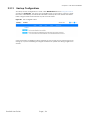
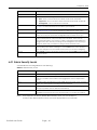
2.3.9 Turn Service On
At this point, both the BU and RUs should be fully configured. This means the system is ready
for activation through turning on Service.
Turning on “Service” allows RF signals into the system for distribution. ON represents the
normal working state for a ZoneDAS system. ZoneDAS is effectively “under maintenance”
when Service is off.
La pagina si sta caricando...
La pagina si sta caricando...
La pagina si sta caricando...
La pagina si sta caricando...
La pagina si sta caricando...
La pagina si sta caricando...
La pagina si sta caricando...
La pagina si sta caricando...
La pagina si sta caricando...
La pagina si sta caricando...
La pagina si sta caricando...
La pagina si sta caricando...
La pagina si sta caricando...
La pagina si sta caricando...
La pagina si sta caricando...
La pagina si sta caricando...
La pagina si sta caricando...
La pagina si sta caricando...
La pagina si sta caricando...
La pagina si sta caricando...
La pagina si sta caricando...
La pagina si sta caricando...
La pagina si sta caricando...
La pagina si sta caricando...
La pagina si sta caricando...
La pagina si sta caricando...
La pagina si sta caricando...
La pagina si sta caricando...
La pagina si sta caricando...
La pagina si sta caricando...
La pagina si sta caricando...
La pagina si sta caricando...
La pagina si sta caricando...
La pagina si sta caricando...
La pagina si sta caricando...
La pagina si sta caricando...
La pagina si sta caricando...
La pagina si sta caricando...
La pagina si sta caricando...
La pagina si sta caricando...
La pagina si sta caricando...
La pagina si sta caricando...
-
 1
1
-
 2
2
-
 3
3
-
 4
4
-
 5
5
-
 6
6
-
 7
7
-
 8
8
-
 9
9
-
 10
10
-
 11
11
-
 12
12
-
 13
13
-
 14
14
-
 15
15
-
 16
16
-
 17
17
-
 18
18
-
 19
19
-
 20
20
-
 21
21
-
 22
22
-
 23
23
-
 24
24
-
 25
25
-
 26
26
-
 27
27
-
 28
28
-
 29
29
-
 30
30
-
 31
31
-
 32
32
-
 33
33
-
 34
34
-
 35
35
-
 36
36
-
 37
37
-
 38
38
-
 39
39
-
 40
40
-
 41
41
-
 42
42
-
 43
43
-
 44
44
-
 45
45
-
 46
46
-
 47
47
-
 48
48
-
 49
49
-
 50
50
-
 51
51
-
 52
52
-
 53
53
-
 54
54
-
 55
55
-
 56
56
-
 57
57
-
 58
58
-
 59
59
-
 60
60
-
 61
61
-
 62
62


ZyXEL Communications ZoneDAS Manuale utente
- Tipo
- Manuale utente
in altre lingue
Altri documenti
-
Juniper MX204 Manuale utente
-
Juniper ACX5448 Manuale utente
-
-
-
Juniper PTX1000 Manuale utente
-
Cisco 7606 Guida d'installazione
-
-
-
-
AJA OG-X-FR Manuale utente