
Paragon
®
II
User Guide
Release 4.1
Copyright © 2006 Raritan Computer, Inc.
PII-0J-E
April 2006
255-30-6000

This page intentionally left blank.

Copyright and Trademark Information
This document contains proprietary information that is protected by copyright. All rights reserved.
No part of this document may be photocopied, reproduced, or translated into another language
without express prior written consent of Raritan Computer, Inc.
©Copyright 2006 Raritan, Paragon, Paragon Manager, IP-Reach, Z-Series, and the Raritan
company logo are trademarks or registered trademarks of Raritan Computer, Inc. All rights
reserved. Java is a registered trademark of Sun Microsystems, Inc. Internet Explorer is a
registered trademark of Microsoft Corporation. Netscape and Netscape Navigator are registered
trademarks of Netscape Communication Corporation. All other marks are the property of their
respective owners.
FCC Information
This equipment has been tested and found to comply with the limits for a Class A digital device,
pursuant to Part 15 of the FCC Rules. These limits are designed to provide reasonable protection
against harmful interference in a commercial installation. This equipment generates, uses, and can
radiate radio frequency energy and if not installed and used in accordance with the instructions,
may cause harmful interference to radio communications. Operation of this equipment in a
residential environment may cause harmful interference.
Japanese Approvals
Raritan is not responsible for damage to this product resulting from accident, disaster, misuse,
abuse, non-Raritan modification of the product, or other events outside of Raritan’s reasonable
control or not arising under normal operating conditions.
LISTE
D
C
US
L
U
1F61
I.T.E.
For assistance in the North or South America, please contact the Raritan Technical Support Team
by telephone (732) 764-8886, by fax (732) 764-8887, or by e-mail [email protected]
Ask for Technical Support – Monday through Friday, 8:00am to 8:00pm, Eastern.
For assistance around the world, please see the last page of this guide for
regional Raritan office contact information.

Safety Guidelines
To avoid potentially fatal shock hazard and possible damage to Raritan equipment:
• Do not use a 2-wire power cord in any product configuration.
• Test AC outlets at your computer and monitor for proper polarity and grounding.
• Use only with grounded outlets at both the computer and monitor. When using a backup UPS,
power the computer, monitor and appliance off the supply.
Rack Mount Safety Guidelines
In Raritan products which require Rack Mounting, please follow these precautions:
• Operation temperature in a closed rack environment may be greater than room temperature.
Do not exceed the rated maximum ambient temperature of the appliances (see Appendix A:
Specifications).
• Ensure sufficient airflow through the rack environment.
• Mount equipment in the rack carefully to avoid uneven mechanical loading.
• Connect equipment to the supply circuit carefully to avoid overloading circuits.
• Ground all equipment properly, especially supply connections, such as power strips (other
than direct connections), to the branch circuit.

CONTENTS i
Contents
Chapter 1: Introduction .................................................................. 1
Paragon II Overview...................................................................................................................1
Product Photos...........................................................................................................................2
Product Features........................................................................................................................3
Package Contents......................................................................................................................4
Chapter 2: Installation.................................................................... 5
Basic Installation........................................................................................................................5
Initial Administrative Testing................................................................................................6
Paragon II Front Panel Display and Controls ............................................................................7
Initial Configuration ..................................................................................................................12
Using the OSUI for Initial Configuration...................................................................................12
Installing a Paragon System with a Single Base Unit..............................................................14
Installing a Cascaded Paragon System...................................................................................17
Installing the Paragon P2-UMT832S Stacking Unit...........................................................21
Installing the Paragon P2-UMT1664S Stacking Unit ........................................................21
Installing a HubPac............................................................................................................22
Chapter 3: Operation – User Functions ........................................ 25
Login.........................................................................................................................................25
Manual Video Gain and Automatic Skew Compensation in P2-EUST....................................27
Video Gain Adjustment in P2-UST....................................................................................28
Selecting a Server....................................................................................................................29
User Profile Customization ......................................................................................................33
User Profile Parameters and How to Change Settings.....................................................34
Help Menu................................................................................................................................35
Keyboard-Controlled OSUI Functions......................................................................................36
Information Menu.....................................................................................................................37
Chapter 4: Operation – Administrator Functions ......................... 39
The Administration Menu.........................................................................................................39
Guidelines for System Configuration .......................................................................................40
System Configuration...............................................................................................................40
Video Redirection (Forced Switching)......................................................................................42
User Configuration...................................................................................................................43
Channel Configuration .............................................................................................................45
Video Display Adjustment for P2-EUST............................................................................47
User Station Profile..................................................................................................................48
Keyboard Type..................................................................................................................48
Video Delay .......................................................................................................................49
Group Settings (Access Rights)...............................................................................................50
Recommendations...................................................................................................................51
System Reboot and System Reset..........................................................................................52
System Reboot..................................................................................................................52
System Reset ....................................................................................................................53
Network Settings......................................................................................................................54
Autoscan and Autoskip ............................................................................................................55
Power Management.................................................................................................................55
Configuring and Naming the Power Strip..........................................................................55
Associating a Target with a Power Outlet .........................................................................56
Controlling Power to an Outlet...........................................................................................56
Paragon II Network Port...........................................................................................................57
Chapter 5: Paragon II and Z-CIMs ................................................ 59
Introduction ..............................................................................................................................59
UKVMSPD (and UKVMSC) Z-CIMs..................................................................................59
P2ZCIMs............................................................................................................................60
Paragon II and UKVMSPD Z-CIMs..........................................................................................61
Using a UKVMSPD with a Local PC .................................................................................61
Connecting Z-CIMs and P2ZCIMs as Tiers.......................................................................62

ii CONTENTS
Resize or Refresh a P2ZCIM Chain..................................................................................65
P2ZCIMs............................................................................................................................65
Connecting P2ZCIMs as Tiers...........................................................................................65
P2ZCIM LED Status..........................................................................................................68
Chapter 6: Configurations ............................................................ 69
Principles of Re-Connection ....................................................................................................69
Tiered Configurations...............................................................................................................70
Standard Tiering Configurations........................................................................................70
Stacked Configurations............................................................................................................72
Standard Stacking Configurations.....................................................................................73
Non-Standard Tier Configuration.............................................................................................76
Guidelines for Existing Firmware Versions........................................................................76
Illegal Configuration .................................................................................................................79
Loop-Back Configuration..........................................................................................................79
Appendix A: Specifications .......................................................... 81
CAT5 Cable Guidelines............................................................................................................83
Appendix B: User Station Direct Mode ........................................ 85
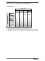
Appendix C: Tiering and Compatibility ........................................ 87
Tiering Matrix ...........................................................................................................................87
Compatibility Matrix..................................................................................................................88
Appendix D: Paragon II Rack Mount ............................................ 89
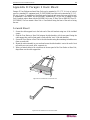
Forward Mount.........................................................................................................................89
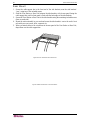
Rear Mount ..............................................................................................................................90
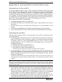
Appendix E: Using AUATC for RS-232 Access ............................. 91
Introduction to the AUATC.......................................................................................................91
Installing the AUATC................................................................................................................91
Operating the AUATC..............................................................................................................92
Screen Layout ...................................................................................................................92
On Line Mode....................................................................................................................93
Help Mode .........................................................................................................................94
Buffer Edit Mode................................................................................................................95
Configuring the AUATC............................................................................................................96
Troubleshooting the AUATC....................................................................................................98
Appendix F: Emulating Sun Keys with a PS/2 Keyboard ............. 99
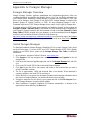
Appendix G: Paragon Manager................................................... 101
Paragon Manager Overview..................................................................................................101
Install Paragon Manager........................................................................................................101
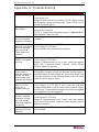
Appendix H: Troubleshooting..................................................... 103
Multi-Tier Installation..............................................................................................................104
Paragon II FAQs Online .............................................................. 105

FIGURES iii
Figures
Figure 1 Paragon II Main Units ....................................................................................................................2
Figure 2 P2-UMT832, P2-UST, and P2CIM-PS2.........................................................................................2
Figure 3 P2-EUST........................................................................................................................................3
Figure 4 Installation Diagram.......................................................................................................................5
Figure 5 Login Menu....................................................................................................................................6
Figure 6 Selection Menu..............................................................................................................................7
Figure 7 Paragon II Front Panel Buttons......................................................................................................7
Figure 8 LCD Normal Display ......................................................................................................................8
Figure 9 Power Up Clear Database.............................................................................................................8
Figure 10 LCD Functions.............................................................................................................................9
Figure 11 Function Selection .......................................................................................................................9
Figure 12 Display Ver. and SN.....................................................................................................................9
Figure 13 User Station Test.........................................................................................................................9
Figure 14 Channel CIM (UKVM) Test.......................................................................................................10
Figure 15 Stacking Support........................................................................................................................10
Figure 16 Set LCD Contrast.......................................................................................................................10
Figure 17 Auto Configure...........................................................................................................................10
Figure 18 Format of OSUI screens............................................................................................................12
Figure 19 Login Menu for a Paragon II ......................................................................................................14
Figure 20 Selection Menu..........................................................................................................................15
Figure 21 Administration Menu..................................................................................................................16
Figure 22 Channel Configuration Menu of a P2-UMT832M.......................................................................16
Figure 23 Sample cascaded system..........................................................................................................17
Figure 24 Selection Menu..........................................................................................................................18
Figure 25 Administration Menu..................................................................................................................19
Figure 26 Channel Configuration Menu for a P2-UMT832M......................................................................19
Figure 27 Paragon HubPac........................................................................................................................22
Figure 28 Connecting a P2-UMT832M to a HubPac..................................................................................23
Figure 29 Login Menu................................................................................................................................25
Figure 30 Selection Menu for a P2-UMT832M...........................................................................................26
Figure 31 Manual Video Gain/Skew Delay Adjustment Display for P2-EUST............................................27
Figure 32 Manual Video Gain Adjustment for P2-UST...............................................................................28
Figure 33 Selection Menu in order by Channel Port Number.....................................................................29
Figure 34 Selection Menu in order by Port Name......................................................................................29
Figure 35 User Profile Menu......................................................................................................................33
Figure 36 Directional Prompts in Message Bar..........................................................................................33
Figure 37 Prompt in Message Bar to Save Changes.................................................................................35
Figure 38 Help Menu .................................................................................................................................35
Figure 39 Information Menu.......................................................................................................................37
Figure 40 Administration Menu..................................................................................................................39
Figure 41 System Configuration Menu for P2-EUST .................................................................................40
Figure 42 Force Switch Message...............................................................................................................42
Figure 43 Left panel of the User Configuration Menu ................................................................................43
Figure 44 Right panel of the User Configuration Menu..............................................................................44
Figure 45 Left panel of the Channel Configuration Menu...........................................................................45
Figure 46 Right panel of the Channel Configuration Menu ........................................................................46
Figure 47 Selection Menu..........................................................................................................................47
Figure 48 Selection Menu with RGB Skew Delay Active ...........................................................................47
Figure 49 User Station Profile Screen........................................................................................................48
Figure 50 System Reboot Confirmation.....................................................................................................52
Figure 51 System/Device Reset Screen....................................................................................................53

iv FIGURES
Figure 52 Network Settings Menu..............................................................................................................54
Figure 53 Close-up of CIM Chain between Servers...................................................................................60
Figure 54 User Profile Menu......................................................................................................................61
Figure 55 Connecting Z-CIMs or P2ZCIMs as Tiers..................................................................................62
Figure 56 Connecting P2ZCIMs as Tiers to Paragon II..............................................................................65
Figure 57 Resize the P2ZCIM Chain .........................................................................................................67
Figure 58 Refresh the P2ZCIM Chain........................................................................................................67
Figure 59 Single Base Configuration .........................................................................................................70
Figure 60 Multiple Base Configuration.......................................................................................................71
Figure 61 Stacking - Single Base Configuration with P2-UMT1664M and P2-UMT1664S ........................73
Figure 62 Stacking - Single Base Configuration with P2-UMT832M and P2-UMT832S ............................73
Figure 63 Stacking - Single Base Configuration with P2-UMT1664M and P2-UMT1664S ........................73
Figure 64 Stacking - Single Base Configuration with P2-UMT832M and P2-UMT832S ............................74
Figure 65 Stacking - Single Base Configuration with P2-UMT1664M and P2-UMT832S ..........................74
Figure 66 Illegal Stacking - Single Base Configuration with P2-UMT1664M and P2-UMT1664S..............75
Figure 67 Illegal Stacking - Single Base Configuration with P2-UMT1664M and P2-UMT832S................75
Figure 68 Illegal Stacking - Single Base Configuration with P2-UMT1664M and two P2-UMT1664S........75
Figure 69 Triangle Configuration................................................................................................................76
Figure 70 Diamond Configuration..............................................................................................................77
Figure 71 Redundant Configuration...........................................................................................................78
Figure 72 Recommended Redundant Configuration connection scheme..................................................79
Figure 73 Illegal Loop-Back Configuration.................................................................................................79
Figure 74 Cat5 Cable Diagram ..................................................................................................................83
Figure 75 Front rackmount of a P2 Base Unit............................................................................................89
Figure 76 Front rackmount of a P2 User Station........................................................................................89
Figure 77 Rear rackmount of a P2 Base Unit.............................................................................................90
Figure 78 Rear rackmount of a P2 User Station ........................................................................................90
Figure 79 AUATC screen layout (On Line Mode).......................................................................................92
Figure 80 Help screen................................................................................................................................94
Figure 81 Buffer Edit Mode screen ............................................................................................................95
Figure 82 Setup Communication Screen ...................................................................................................96
Figure 83 Set Up Programmable Keys screen...........................................................................................97

CHAPTER 1: INTRODUCTION 1
Chapter 1: Introduction
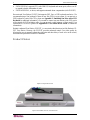
Thank you for purchasing Raritan’s Paragon II. The Paragon family is about breaking away from
the traditional, expensive model of server management – one server, one dedicated monitor, one
dedicated keyboard. Paragon allows for a single user station (monitor, keyboard, and mouse) for
multiple servers – even servers of different platforms.
No matter how large or small your setup, no matter how simple or how complex, Raritan is
confident that there is a Paragon system just right for you.
Paragon II Overview
The Paragon II is designed to perform heavy-duty multiple-user-to-many-server
keyboard/video/mouse (KVM) matrix switching without burdening you with big, confusing
hydra-headed cables. Instead, the Paragon II uses standard Category 5 unshielded twisted-pair
(UTP) cabling, like the type that is already installed at many sites. It can connect users with
servers across as much as 1000 ft. (304 m) of such cabling.
A Paragon II system consists of several components: Main switching units (M Units), which
serve as base units and matrix switches, securely connecting users to servers; Stacking units (S
Units), which allow you to expand your system and connect to the M Units while conserving
space; Computer-Interface Modules (CIMs) connected to each server; and either the User Station
(P2-UST), which connects your keyboard, monitor, and mouse to the M unit and provides an
intuitive On-Screen User Interface for accessing attached servers, or the Enhanced User Station
(P2-EUST), providing all of the P2-UST features, plus superior video quality with manual skew
compensation.
In addition, Raritan’s P2-USTIP1 and P2-USTIP2, one-and two-worker user stations, have
integrated IP access and includes KVM over IP capability for anytime, anywhere access and
control of servers along with a slim design and GUI for point-and-click remote access. The P2-
USTIP supports IP access, enabling one or two remote users to access Paragon II-connected
servers from anywhere via Web browser. The P2-USTIP2 also supports 128-bit SSL encryption
and local authentication through Paragon II, or centralized authentication when used with
Raritan’s CommandCenter Secure Gateway.
There are a number of Main Switching Units that support different numbers of directly attached
users and server CPUs:
• Product code P2-UMT242 supports 2 users and 42 CPUs
• P2-UMT442 supports 4 users and 42 CPUs
• P2-UMT832M supports 8 users and 32 CPUs
• P2-UMT1664M supports 16 users and 64 CPUs
There are also several different CIMs for different types of servers (all must output VGA video):
• P2CIM-PS2 and ZCIM-PS2 support CPUs with IBM PS/2 type keyboard and mouse ports;
Z-CIM has an extra RJ45 port to support a “local CPU” installed between a User Station and
a Base Unit, as well as chaining of Z-CIMs for clustered access.
• P2CIM-APS2, as above, and supports automatic skew compensation (with P2-EUST).
• P2CIM-SUN supports CPUs with Sun type keyboard and mouse ports.
• P2CIM-ASUN, as above, and supports automatic skew compensation (with P2-EUST).
• P2CIM-USB, P2CIM-SUSB, and P2CIM-USBG2 support CPUs with USB keyboard and
mouse ports.
• P2CIM-AUSB, as above, will work for SUN, and supports automatic skew compensation
(with P2-EUST).
• P2CIM-USBG2 works with P2-HUBPAC in PC, MAC, and SUN USB configurations.
• AUATC supports CPUs connected through their RS-232 serial ports.

2 PARAGON II USER GUIDE
• P2CIM-PS2DUAL supports CPUs with IBM PS/2 keyboard and mouse ports; allows one PC
to expand to double the number of users.
• P2CIM-APS2DUAL, as above, and supports automatic skew compensation (with P2-EUST).
One universal User Station (P2-UST) that supports PS/2, Sun, or USB keyboards and mice. (We
recommend using a Sun keyboard if there are any Sun CPUs in your system; if you must use a
PS/2 keyboard to control Sun CPUs, please see Appendix F: Emulating Sun Keys with a PS/2
Keyboard for additional information.) If you want to connect one user station to one CPU across
a long stretch of CAT5 or higher cable, you can run such a cable between a “direct mode” User
Station and a P2CIM-PS2 (please see Appendix B: User Station Direct Mode for additional
information).
Raritan’s enhanced User Station, P2-EUST, is a user station that functions just like Raritan’s P2-
UST User Station. However, the P2-EUST provides enhanced control over video quality by
allowing the user to manually adjust the video gain and skew delay of each color on the screen,
and store these preferences in the UMT database.
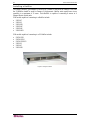
Product Photos
Figure 1 Paragon II Main Units
Figure 2 P2-UMT832, P2-UST, and P2CIM-PS2

CHAPTER 1: INTRODUCTION 3
Figure 3 P2-EUST
Product Features
• 2U design supports 16 users, 64 servers (model P2-UMT1664M)
• 1U design supports 8 users, 32 servers (model P2-UMT832M)
• 1U design supports 4 users, 42 servers (model P2-UMT442)
• 1U design supports 2 users, 42 servers (model P2-UMT242)
• Expands to 32 users with Raritan’s P2CIM-PS2DUAL or P2-HUBPAC
• Expands to 32 users with Raritan’s HUBPAC8
• Locates users and servers up to 1000 feet (304 m) apart
• Supports high-resolution video – up to 1600 x 1200
• Supports up to 512 customized user profiles (with optional Memory Card)
• Adds remote access over IP or modem with Raritan’s IP-Reach and UST-IP models
• Expands to 10,000 servers via multi-dimensional expansion (with optional Memory Card)
• Stacking switches provide 100% non-blocked expansion with a single cable
• Enclosed 19” rack mounts with included brackets
• Simple plug-and-play auto-configure installation
• Hot-swappable components with no impact on server operation
• Platform-specific CIMs for PS/2, Sun, USB, Sun USB, ASCII/serial devices
• Powerful, intuitive on-screen user interface for simple operation
• Flexible, multi-level security for authorized server access
• Three system operation modes - private, public, and share
• Flash firmware upgrades via network port
• Paragon Manager, a Windows application, provides streamlined administration of Paragon II
infrastructure, including adding, deleting or modifying user profiles, event logging, and
database backup/restore (please see Raritan’s Paragon Manager User Guide for additional
information on Paragon Manager, located on the User Manuals and Quick Setup Guides
CDROM included with your Paragon unit, or:
http://www.raritan.com/support/sup_prdmanuals.aspx
)
• OSUI support for IBM x330 with C2T technology
• Administrator can logoff any connected user
• Turn on, off, or reboot power to any connected device
• Network admin port
• Set power control permissions on a per outlet basis

4 PARAGON II USER GUIDE
Package Contents
Each Paragon Main Unit (P2-UMT242, P2-UMT442, P2-UMT832M, or P2-UMT1664M) ships
with:
• (1) Base Unit
• (2) 20-ft. (6.1-m) CAT5 test cables
• (1) Pair of Rackmount brackets and associated screws
• (1) 6-ft. (1.8-m) AC power cord
• RUMT-1U-LM304 Rackmount kit
• CAT5 admin cable
• Raritan’s User’s Manual CD
• Quick Setup and Installation Guide
The Paragon Stacking Units ship with:
• (1) Stacking Switch
• RUMT-1U-LM304 Rackmount kit
• (1) 6” Stacking Cable (for use with P2-UMT832M) or (2) 6” Stacking Cables (for use with
P2-UMT1664M)
• AC Power Cord
The Paragon User Stations (both P2-UST and P2-EUST) ship with:
• (1) User-Station Module
• (1) 6-ft. (1.8-m) AC power cord
• (1) 6-ft. (1.8-m) AC power-extension cord for the attached monitor
• (1) 10-ft. (3-m) DB9 male-to-female serial administration cable

CHAPTER 2: INSTALLATION 5
1 3
4
5
6
7
8
2
O
p
tiona
l
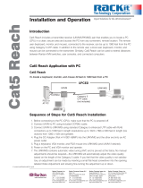
Chapter 2: Installation
Important: The Paragon and all devices you want to attach to it must be unplugged and
powered OFF prior to installation.
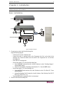
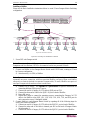
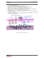
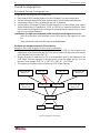
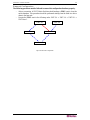
Basic Installation
Figure 4 Installation Diagram
1. Connect power cord to the Main Switching Unit.
Optional Stacking Support:
− Connect power cord to a Stacking Unit.
− Connect one end of a stacking cable to the "Expansion Port Out" on the back of the
Stacking Unit. Connect the other end of the cable to the "Expansion Port" on the Main
Switching Unit
− Power ON all switching units
− On the front panel LCD of the Main Switching Unit:
Press the FUNC button and use the Ç and È buttons to select "Stacking Support."
Press the ENT button.
Select the total number of Stacking Units desired (0-3). Press the ENT button.
− On the front panel LCD of the Stacking Unit:
Press the FUNC button and use the Ç and È buttons to select "Set Stack ID." Press
the ENT button.
Assign the Stacking Unit ID using the Ç and È buttons. Each Stacking Unit MUST
HAVE A UNIQUE ID (1-3)
− Press the ENT button (sequential order is not necessary).
2. Power ON the Main Switching Unit.
P2-UST or P2-EUST
M Unit
S Unit

6 PARAGON II USER GUIDE
3. Connect one end of a Category 5e UTP cable to User Port #1 on the back of the Main
Switching Unit. Connect the other end of the cable to the “Cat5 Port” on the back of the User
Station (P2-UST or P2-EUST).
4. Connect a power cord to the User Station. Power ON the User Station.
5. Connect a PS/2 keyboard, mouse, and VGA monitor to the User Station. Power ON the
monitor.
6. Connect one end of a Category 5e UTP cable to Channel Port #1 on the back of the Main
Switching Unit (or Stacking Unit, if attached). Connect the other end of the cable to the RJ45
port on a Computer Interface Module (P2-CIM).
7. Connect the P2-CIM to server’s keyboard, video, and mouse ports.
8. Power ON server.
9. Repeat steps 3 through 8 for all other CPUs you want to attach.
Note: Although users and servers can be located up to 1000 (304 m) apart, for optimal video
quality, limit cable length between the Main Switching Unit and CIM to less than 100 feet (30.5
m). For good video quality, limit cable length between the Main Switching Unit and CIM to less
than 500 feet (152 m).
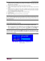
Initial Administrative Testing
To verify that an attached server can be viewed and controlled through the Paragon system:
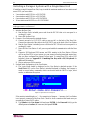
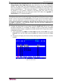
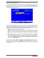
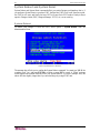
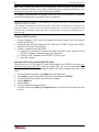
1. When you first power ON the Paragon Base Unit, an attached User Station, and the User
Station’s attached monitor; the Login screen appears. Type admin in the User Name field
and press ENTER. Type raritan (all lowercase) in the Password field and press ENTER.
Note: The factory-default user names are user01 through up to user16 (depending on the model
of the Base Unit) for regular users and admin for the admin user. User names are not case-
sensitive. By default, a password is required only for the admin user, and that password is raritan.
Passwords are case-sensitive.
Figure 5 Login Menu

CHAPTER 2: INSTALLATION 7
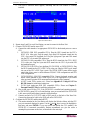
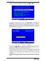
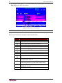
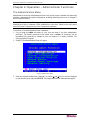
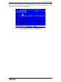
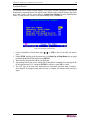
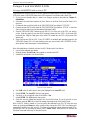
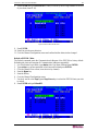
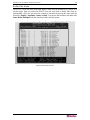
2. The On-Screen User Interface (OSUI) Selection Menu appears. The ports of connected CPUs
appear in green. At the start, there will be no default name and the Name field will be blank.)
Figure 6 Selection Menu
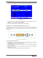
3. Press the Ç and È (up- and down-arrow) keys on the user station keyboard to move the
highlight to the green server port and press ENTER.
4. Normal server access and operation indicates a successful connection.
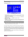
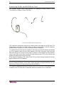
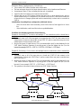
Paragon II Front Panel Display and Controls
The control buttons and LCD display on the Paragon II unit provide systems management and
technical support functions. For most situations, there is no need to use the front panel beyond
viewing status.
ENT
FUNC
ESC
Figure 7 Paragon II Front Panel Buttons
Front Panel Components and Functions:
1. The ESC button is used for canceling displayed function and returning system to normal state.
2. The FUNC button is used to select various functions.
3. The LCD displays system status and indicates functions that can be selected by pressing front
panel control buttons.
4. The Å, Ç, Æ, and È buttons are used for selecting or setting various options, depending on
function being performed.
5. The ENT button is used for confirming and executing selected function.

8 PARAGON II USER GUIDE
Start-Up Display:
When a Paragon II unit is powered ON, it performs a start-up test. It checks each channel and
user port to ensure proper operation.
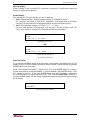
Normal Display:
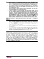
After start-up test, LCD panel displays two lines of messages:
1. Line 1: Running message: “Raritan Computer Paragon II: Paragon832/1 Ready”
For a Paragon II unit model P2-UMT832M, “Paragon832” is the default name of the Matrix
Switching Unit (this name may be changed through the System Configuration Menu).
2. Line 2: User port status message: “A/N User (1, 2, 3 …) → None”
User port status displays a scrolling status of all user ports, one user port per second. The
User’s active channel, 1 through 128, is displayed after the user port number.
Raritan Computer Paragon II: Paragon832/1
Ready
A User (1, 2, 3 … 8) → None
A=Active User # 1-8
- OR -
Raritan Computer Paragon II: Paragon832/1
Ready
N User (1, 2, 3, … 8) → None
N=Non-Active User # 1-8
Figure 8 LCD Normal Display
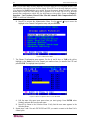
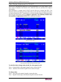
Power Up Option:
If you hold down the FUNC button on the front panel of the Paragon II unit during Power Up, the
Paragon II unit will clear its database and reset to factory defaults. Confirm functions by pressing
the ENT button on the front panel.
When “Clear Database Hit Ent/ESC?” appears on the LCD, press the ESC button if you want to
exit the screen without clearing the database. To clear the database, press the ENT button; “Clear
All?” appears on the LCD. If you press the ESC button once more, the channel configuration
will be cleared and will be rebuilt later by the UMT. This is called a Partial Reset. However, if
you press the ENT button, both the channel configuration and the user profile and system settings
will be cleared.
Clear Database
Hit Ent/ESC?
Figure 9 Power Up Clear Database

CHAPTER 2: INSTALLATION 9
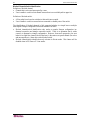
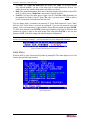
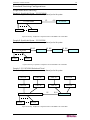
Function Selection Screen:
Several administrative functions can be performed on the Function Selection Screen on the
Paragon II unit’s front panel.
Display Ver./SN
Test User UST1
Test Chan. UKVM
Test Stack Unit
Stacking Support
Set LCD Contrast
Re-Configure
Set IP Address
Reset Unit
Figure 10 LCD Functions
Selecting a Function:
Press the FUNC button on the front panel of the Paragon II unit to enter Function Selection mode
and use the Ç and È buttons to scroll through the Function List. Press the ENT button on the
front panel to select displayed function and use the instructions below for each specified function.
Press the ESC button on the front panel at any time to return to Normal Display.
Function Menu
Display Ver./SN
Figure 11 Function Selection
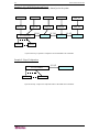
1. Display Ver./SN (Firmware Version and Serial Number): Displays current version of
firmware, the firmware loader, the unit’s serial number, and the field programmable gate
array (FPGA).
Firmware: 2C1
SN: CPB80347
Figure 12 Display Ver. and SN
2. Test User UST1 (User Station): Used by administrator to check if user stations (UST1s) are
functioning properly. Press the Ç or È button to change user port number. Display will read
“OK”, “None”, or “Failed. Press ESC to return to normal display.”
If a “failed” condition is detected, make sure Category 5e UTP cable is installed properly and
secured, or try using another UST1 to see if UST1 under test has become defective.
Test User UST1
UST1: 3 OK
Figure 13 User Station Test

10 PARAGON II USER GUIDE
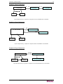
3. Test Channel UKVM (CIM UKVM): Used by administrator to check if CIM is functioning
properly. Press the Ç or È button to change channel number. Display will read “OK”,
“None”, or “Failed.” Press ESC to return to normal display.
If a “failed” condition is detected, make sure Category 5e UTP cable is installed properly and
secured, or try using another CIM (UKVM) to see if CIM under test has become defective.
Test Chan. UKVM
UKVM: 60 OK
Figure 14 Channel CIM (UKVM) Test
4. Test Stack Unit: Press the Ç or È button to select the corresponding Stacking Unit ID for
any connected units. If there are no Stacking Units connected, the LCD will display “None”.
If there are Stacking Units connected, the LCD should read “OK” for each unit. Press ESC
to return to normal display.
5. Stacking Support: Press the Ç or È button to set the Stacking Unit ID number (0 – 3 for a
P2-UMT832M or “0” or “1” for a P2-UMT1664M). The default is set to “0” (no Stacking
Units connected). If you wish to add Stacking Units, this number must be equal to the
number of Stacking Units connected. Press ESC to return to normal display.
Stacking Support
Unit(s): 0-3
Figure 15 Stacking Support
6. Set LCD Contrast: Modifies contrast level of front panel LCD Display. Press the Ç or È
button to increase or decrease contrast, and press the ESC button to return to normal display.
Set LCD Contrast
Use Up/Down Keys
Figure 16 Set LCD Contrast
Note: LCD contrast can also be adjusted by holding the
Å
button and pressing the
Ç
or
È
button at any time.
7. Re-Configure: Paragon II will automatically configure the system as computers or devices
are added or removed. However, the system administrator can use this function to scan and
re-configure the system manually. When complete, it will return to normal display.
Re-Configure
Searching Now…
Figure 17 Auto Configure
8. Set IP Address: As administrator, you may change Paragon II’s IP address directly from the
front panel of the device. The Paragon II’s current IP address will be displayed, along with a
cursor. Use the Å and Æ keys to move the cursor over digit-by-digit, and use the Ç or È
arrow keys to change the value of that digit. Press the ENT button when the new IP address
has been set. Press the ENT button again to save changes and reboot the unit when asked to
“Save Changes?” The unit will restart with the new network address.

CHAPTER 2: INSTALLATION 11
Note: Stacking units do not have their own databases and configurations settings, and likewise,
do not have their own network addresses. You cannot configure one using the front panel
controls on UMT S units.
9. Reset Unit (Paragon II Unit Switch): Enables restart of Paragon II unit as if unit’s power had
been physically turned off and back on again.
With Paragon II unit firmware 2B1 and User Station (UST1) firmware 2K10 or higher, either
a power reset or a factory “function” reset can be performed from the front panel of the
Paragon II unit using shortcut button combinations.
Power Reset:
Hold the Ç and È buttons on the front panel of the Paragon II unit simultaneously for
approximately three seconds. When the front panel stops scrolling, release the buttons.
Factory “Function” Reset:
Hold the Ç and È buttons on the front panel of the Paragon II unit simultaneously while pressing
the FUNC button. When the front panel stops scrolling, release the Ç and È buttons, wait an
additional three seconds, then release the FUNC button.
When “Clear Database Hit Ent/ESC?” appears on the LCD, press the ESC button if you want to
exit the screen without clearing the database. To clear the database, press the ENT button; “Clear
All?” appears on the LCD. If you press the ESC button once more, the channel configuration
will be cleared and will be rebuilt later by the UMT. This is called a Partial Reset. However, if
you press the ENT button, both the channel configuration and the user profile and system settings
will be cleared.

12 PARAGON II USER GUIDE
Initial Configuration
Note: This section includes full instructions for how to install single Base Units, cascades of
multiple base units, or stacking switches. Follow the simplified procedure previously outlined in
Basic Installation to install a simple Paragon system with a single Base Unit. See Appendix B:
User Station Direct Mode, to install a “direct mode” User Station-to-CIM system with no Base
Units. See Chapter 5: Paragon II and Z-CIM to install a Z-CIM and a local PC in your system.
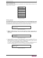
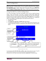
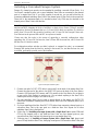
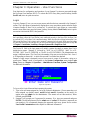
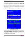
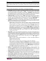
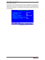
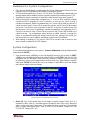
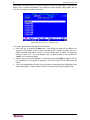
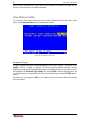
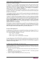
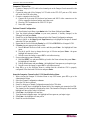
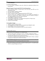
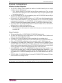
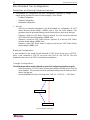
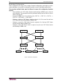
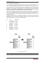
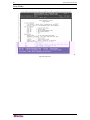
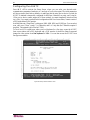
Using the OSUI for Initial Configuration
You will use the Paragon II On-Screen User Interface (OSUI) while you install the Paragon
system, so here are some basics of the OSUI to familiarize yourself before starting your
installation. Once the User Station and user-station equipment are in place and powered ON,
activate the OSUI by rapidly pressing the default hotkey (Scroll Lock) twice on an attached
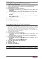
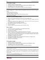
keyboard. Each OSUI menu contains the following sections: a menu-title line, a menu/screen
body (for text and fields), a prompt/message bar, and a status line that consists of:
• The current OSUI hotkey
• Scan/Skip status
• NCS (Num Lock, Caps Lock, and Scroll Lock) status indicator
• A communication-speed indicator (“L” for low or “H” for high, which will depend on your
Paragon components) showing the communication speed between the User Station and Base
Station.
Figure 18 Format of OSUI screens
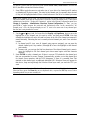
Use function keys F1, F2, F3, F4, F8, and F12 to toggle between first-level menus. Press F1
while the OSUI is displayed to activate the Help Menu, a list of available help options.
While the OSUI is on screen, the user-station keyboard’s Scroll Lock LED indicator blinks.
Title Line
Menu/Screen
Body (for text
and fields)
Messages Banner
Status Line –
displays….
…the current OSUI hot
key activator (in this
case, the Scroll Lock
key)
…Scan/Skip status
(if yellow, option is
ON; if white, option
is OFF)
…(N) Num Lock, (C) Caps Lock, (S) Scroll
Lock, followed by P2 Communication Speed
Indicator: (L) Low or (H) High (speed can
depend on your component versions)
La pagina si sta caricando...
La pagina si sta caricando...
La pagina si sta caricando...
La pagina si sta caricando...
La pagina si sta caricando...
La pagina si sta caricando...
La pagina si sta caricando...
La pagina si sta caricando...
La pagina si sta caricando...
La pagina si sta caricando...
La pagina si sta caricando...
La pagina si sta caricando...
La pagina si sta caricando...
La pagina si sta caricando...
La pagina si sta caricando...
La pagina si sta caricando...
La pagina si sta caricando...
La pagina si sta caricando...
La pagina si sta caricando...
La pagina si sta caricando...
La pagina si sta caricando...
La pagina si sta caricando...
La pagina si sta caricando...
La pagina si sta caricando...
La pagina si sta caricando...
La pagina si sta caricando...
La pagina si sta caricando...
La pagina si sta caricando...
La pagina si sta caricando...
La pagina si sta caricando...
La pagina si sta caricando...
La pagina si sta caricando...
La pagina si sta caricando...
La pagina si sta caricando...
La pagina si sta caricando...
La pagina si sta caricando...
La pagina si sta caricando...
La pagina si sta caricando...
La pagina si sta caricando...
La pagina si sta caricando...
La pagina si sta caricando...
La pagina si sta caricando...
La pagina si sta caricando...
La pagina si sta caricando...
La pagina si sta caricando...
La pagina si sta caricando...
La pagina si sta caricando...
La pagina si sta caricando...
La pagina si sta caricando...
La pagina si sta caricando...
La pagina si sta caricando...
La pagina si sta caricando...
La pagina si sta caricando...
La pagina si sta caricando...
La pagina si sta caricando...
La pagina si sta caricando...
La pagina si sta caricando...
La pagina si sta caricando...
La pagina si sta caricando...
La pagina si sta caricando...
La pagina si sta caricando...
La pagina si sta caricando...
La pagina si sta caricando...
La pagina si sta caricando...
La pagina si sta caricando...
La pagina si sta caricando...
La pagina si sta caricando...
La pagina si sta caricando...
La pagina si sta caricando...
La pagina si sta caricando...
La pagina si sta caricando...
La pagina si sta caricando...
La pagina si sta caricando...
La pagina si sta caricando...
La pagina si sta caricando...
La pagina si sta caricando...
La pagina si sta caricando...
La pagina si sta caricando...
La pagina si sta caricando...
La pagina si sta caricando...
La pagina si sta caricando...
La pagina si sta caricando...
La pagina si sta caricando...
La pagina si sta caricando...
La pagina si sta caricando...
La pagina si sta caricando...
La pagina si sta caricando...
La pagina si sta caricando...
La pagina si sta caricando...
La pagina si sta caricando...
La pagina si sta caricando...
La pagina si sta caricando...
La pagina si sta caricando...
La pagina si sta caricando...
La pagina si sta caricando...
La pagina si sta caricando...
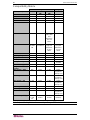
-
 1
1
-
 2
2
-
 3
3
-
 4
4
-
 5
5
-
 6
6
-
 7
7
-
 8
8
-
 9
9
-
 10
10
-
 11
11
-
 12
12
-
 13
13
-
 14
14
-
 15
15
-
 16
16
-
 17
17
-
 18
18
-
 19
19
-
 20
20
-
 21
21
-
 22
22
-
 23
23
-
 24
24
-
 25
25
-
 26
26
-
 27
27
-
 28
28
-
 29
29
-
 30
30
-
 31
31
-
 32
32
-
 33
33
-
 34
34
-
 35
35
-
 36
36
-
 37
37
-
 38
38
-
 39
39
-
 40
40
-
 41
41
-
 42
42
-
 43
43
-
 44
44
-
 45
45
-
 46
46
-
 47
47
-
 48
48
-
 49
49
-
 50
50
-
 51
51
-
 52
52
-
 53
53
-
 54
54
-
 55
55
-
 56
56
-
 57
57
-
 58
58
-
 59
59
-
 60
60
-
 61
61
-
 62
62
-
 63
63
-
 64
64
-
 65
65
-
 66
66
-
 67
67
-
 68
68
-
 69
69
-
 70
70
-
 71
71
-
 72
72
-
 73
73
-
 74
74
-
 75
75
-
 76
76
-
 77
77
-
 78
78
-
 79
79
-
 80
80
-
 81
81
-
 82
82
-
 83
83
-
 84
84
-
 85
85
-
 86
86
-
 87
87
-
 88
88
-
 89
89
-
 90
90
-
 91
91
-
 92
92
-
 93
93
-
 94
94
-
 95
95
-
 96
96
-
 97
97
-
 98
98
-
 99
99
-
 100
100
-
 101
101
-
 102
102
-
 103
103
-
 104
104
-
 105
105
-
 106
106
-
 107
107
-
 108
108
-
 109
109
-
 110
110
-
 111
111
-
 112
112
-
 113
113
-
 114
114
-
 115
115
-
 116
116


Raritan Computer Paragon II Manuale utente
- Tipo
- Manuale utente
- Questo manuale è adatto anche per
in altre lingue
Altri documenti
-
Christie LX1750 Manuale utente
-
 rackit Cat5 Reach Installation And Operation
-
Lindy 32514 Manuale utente
-
Acnodes MKS1604 Manuale utente
-
DirekTronik SKM-04 Manuale utente
-
Smart-AVI SKM-04 Manuale utente
-
Xiaomi MJGJD01YL Manuale utente
-
Intellinet 507844 Manuale utente
-
C2G 89010 Manuale utente
-
3com OfficeConnect 9 Manuale utente
