Hangar 9 HAN4670 Manuale del proprietario
- Categoria
- Giocattoli telecomandati
- Tipo
- Manuale del proprietario
Questo manuale è adatto anche per

OV-10 Bronco 30cc
Instruction Manual
Bedienungsanleitung
Manuel d’utilisation
Manuale di Istruzioni

2EN
NOTICE
All instructions, warranties and other collateral documents are subject to change at the sole discretion of Horizon
Hobby, LLC. For up-to-date product literature, visit horizonhobby.com or www.towerhobbies.com and click on the
support or resources tab for this product.
Age Recommendation: Not For Children Under 14 Years. This Is Not A Toy.
SAFETY WARNINGS AND PRECAUTIONS
Read and follow all instructions and safety precautions before use. Improper use can result in fi re, serious injury and
damage to property.
Components
Use only with compatible components. Should any compatibility questions exist, please refer to the product
instructions, component instructions or contact the appropriate Horizon Hobby offi ce.
Flight
Fly only in open areas to ensure safety. It is recommended fl ying be done at radio control fl ying fi elds. Consult local
ordinances before choosing a fl ying location.
Propeller
Always keep loose items that can become entangled in the propeller away from the prop. This includes loose clothing
or other objects such as pencils and screwdrivers. Keep your hands away from the propeller as injury can occur.
Batteries
Always follow the manufacturer’s instructions when using and disposing of any batteries. Mishandling of Li-Po
batteries can result in fi re causing serious injury and damage.
Small Parts
This kit includes small parts and should not be left unattended near children as choking and serious injury could result.
MEANING OF SPECIAL LANGUAGE
The following terms are used throughout the product literature to indicate various levels of potential harm when
operating this product:
WARNING: Procedures, which if not properly followed, create the probability of property damage, collateral damage,
and serious injury OR create a high probability of superfi cial injury.
CAUTION: Procedures, which if not properly followed, create the probability of physical property damage AND a
possibility of serious injury.
NOTICE: Procedures, which if not properly followed, create a possibility of physical property damage AND a little or
no possibility of injury.
WARNING: Read the ENTIRE instruction manual to become familiar with the features of the product before
operating. Failure to operate the product correctly can result in damage to the product, personal property and
cause serious injury.
This is a sophisticated hobby product. It must be operated with caution and common sense and requires some basic
mechanical ability. Failure to operate this Product in a safe and responsible manner could result in injury or damage
to the product or other property. This product is not intended for use by children without direct adult supervision. Do
not attempt disassembly, use with incompatible components or augment product in any way without the approval
of Horizon Hobby, LLC. This manual contains instructions for safety, operation and maintenance. It is essential to
read and follow all the instructions and warnings in the manual, prior to assembly, setup or use, in order to operate
correctly and avoid damage or serious injury.
SAFE OPERATING RECOMMENDATIONS
• Inspect your model before every fl ight to ensure it is airworthy.
• Be aware of any other radio frequency user who may present an interference problem.
• Always be courteous and respectful of other users in your selected fl ight area.
• Choose an area clear of obstacles and large enough to safely accomodate your fl ying activity.
• Make sure this area is clear of friends and spectators prior to launching your aircraft.
• Be aware of other activities in the vicinity of your fl ight path that could cause potential confl ict.
• Carefully plan your fl ight path prior to launch.
• Abide by any and all established AMA National Model Aircraft Safety Code.
BEFORE STARTING ASSEMBLY
• Remove parts from bag.
• Inspect fuselage, wing panels, rudder and stabilizer for damage.
• If you fi nd damaged or missing parts, contact your place of purchase.
• Charge transmitter and receiver batteries.
• Center trims and sticks on your transmitter.
• For a computer radio, create a model memory for this particular model.
• Bind your transmitter and receiver, using your radio system’s instructions.
NOTICE: Rebind the radio system once all control throws are set. This will keep the servos from moving to their
endpoints until the transmitter and receiver connect. It will also guarantee the servo reversal settings are saved in the
radio system.
FAA INFORMATION
If you own this product, you may be required to register with the FAA.
For up-to-date information on how to register with the FAA, please visit https://registermyuas.faa.gov/.
For additional assistance on regulations and guidance on UAS usage, visit knowbeforeyoufl y.org/.

3 EN
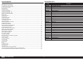
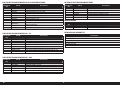
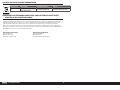
OV-10 Bronco 30cc
Part # Description
HAN467001 Nacelle/Boom; Left-Hand
HAN467002 Nacelle/Boom; Right-Hand
HAN467003 Fuselage
HAN467004 Wing Panel; Left-Hand
HAN467005 Wing Panel; Right-Hand
HAN467006 Wing Panel; Center
HAN467007 Stabilizer with Elevator
HAN467008 Rudders (2)
HAN467009 Cowlings (2)
HAN467010 Cockpit Hatch
HAN467011 Canopy
HAN467012 Pilot Figure
HAN467013 Pushrod Set
HAN467014 Hardware Set
HAN467015 Wheels; (3)
HAN467016 Landing Gear Set
HAN467017 Retract Set; Mains
HAN467018 Retract Unit; Nose
HAN467019 Landing Gear Controller
HAN467020 Retract Motor
HAN467021 Landing Gear Strut Set
HAN467022 Wing Tubes
HAN467023 EP Motor Mounts
HAN467024 Scale Parts
HAN467025 Fuselage Pods/Parts
HAN467026 Missiles and Pylons
HAN467027 Gear Door Set
HAN467028 Painted Spinners (2)
HAN467029 Decal Set
REPLACEMENT PARTS
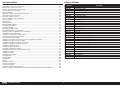
TABLE OF CONTENTS
Notice ......................................................................................................................................................................2
Meaning of Special Language ..................................................................................................................................2
Safety Warnings and Precautions .............................................................................................................................2
Safe Operating Recommendations ...........................................................................................................................2
Before Starting Assembly .........................................................................................................................................2
FAA Information .......................................................................................................................................................2
Replacement Parts ...................................................................................................................................................3
Required for Completion ..........................................................................................................................................4
Required for Completion - EP ...................................................................................................................................4
Required for Completion - Gas .................................................................................................................................4
Optional Parts for Retract Doors ...............................................................................................................................4
Optional Parts ..........................................................................................................................................................4
Required Adhesives .................................................................................................................................................4
Tools Required .........................................................................................................................................................5
Printed Covering Notes ............................................................................................................................................5
Building Precautions ................................................................................................................................................5
Transportation and Storage ......................................................................................................................................5
Checking Blind Nuts.................................................................................................................................................5
Hinging the Stabilizer and Elevator ...........................................................................................................................6
Building Considerations ...........................................................................................................................................6
Stabilizer Servo Installation ......................................................................................................................................8
Aileron and Aileron Servo Installation .....................................................................................................................10
Flap and Flap Servo Installation .............................................................................................................................12
Center Section Servo Leads ...................................................................................................................................14
Rudder and Rudder Servo Installation ....................................................................................................................14
Optional Retract Door Installation ...........................................................................................................................16
Main Gear Retract Installation ................................................................................................................................17
Nose Gear Retract Installation ................................................................................................................................19
Electric Motor Installation .......................................................................................................................................20
Gas Engine Installation ...........................................................................................................................................21
Fuel Tank Installation .............................................................................................................................................23
Gas Engine Spinner and Propeller Preparation .......................................................................................................24
Cowling Installation................................................................................................................................................25
Radio Installation ...................................................................................................................................................27
Accessory Installation ............................................................................................................................................29
Final Assembly .......................................................................................................................................................32
Center of Gravity ....................................................................................................................................................32
Control Throws ......................................................................................................................................................33
Mixing ...................................................................................................................................................................33
Prefl ight Checklist ..................................................................................................................................................33
Daily Flight Checks ................................................................................................................................................33
Limited Warranty ...................................................................................................................................................34
Warranty and Service Contact Information .............................................................................................................35
Instructions for Disposal of WEEE by Users in the European Union ..........................................................................35
Academy of Model Aeronautics National Model Aircraft Safety Code .......................................................................35

4EN
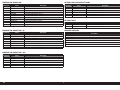
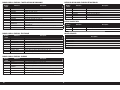
REQUIRED FOR COMPLETION - EP
REQUIRED FOR COMPLETION
REQUIRED FOR COMPLETION - GAS
# Required Part # Description
2 APC18012E Electric Propeller, 18 x 12E
5 CSE011003000 Wire, 36-inch, 10AWG, Black
10 CSE011003100 Wire, 36-inch, 10AWG, Red
4 EFLA266 Gold Bullet Connector Set, 6.5mm
2 GPMG4796 Rimfi re 1.70 63-62-200 Outrunner
4 SPMX50006S50 5000mAh 6S 22.2V Smart 50C; IC5
2
SPMXAE1120HV
Avian 120A Brushless Smart ESC 6S–12S
3 SPMX20002SRX 2000mAh 2S 7.4V Smart LiPo Receiver Battery IC3
# Required Part # Description
1 HAN9151 Aluminum Servo Arm, 1-inch SPM/JR
1 SPM9530 Spektrum 3-Wire Switch Harness
1 SPMA3001 Heavy-Duty Servo Extension 6-inch
12 SPMA3003 Heavy-Duty Servo Extension 12-inch
10 SPMA3006 Heavy-Duty Servo Extension 36-inch
1 SPMA3007 Heavy-Duty Servo Extension 48-inch
1 SPMA3054 Servo Connector Clips (25)
1 SPMAR20310T AR20310T 20CH PowerSafe Tele RX
1 SPMSA6320 A6320 H-T/H-S Brushless HV Servo
9 SPMSA6380 A6380 H-T/H-S Digital HV Servo
1 HAN467016 Landing Gear Set
# Required Part # Description
2 SUL215 2-foot Large ProFlex Universal Tubing
2 APC19080W Competition Propeller,19 x 8W
2 DLEG0031 DLE-30cc Gas Rear Carb with Electronic Ignition Muffl er
2 SPM9530 Spektrum 3-Wire Switch Harness
5 SPMX20002SRX 2000mAh 2S 7.4V Smart LiPo Receiver Battery IC3
2 (or 4) SPMSA6380 A6380 H-T/H-S Digital HV Servo (Throttle and Choke Servo)
# Required Part # Description
2 DUB671 Super Strength Long Servo Arm: JR
4 SPMA3003 Heavy-Duty Servo Extension 12-inch
4 SPMA3005 Heavy-Duty Servo Extension 24-inch
2 SPMA3006 Heavy-Duty Servo Extension 36-inch
1 SPMA3008 Heavy-Duty Y-Harness 6-inch
6 SPMSA5060 A5060 H-T/H-S Mini Metal HV Servo
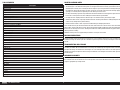
OPTIONAL PARTS FOR RETRACT DOORS
# Required Part # Description
2 EFLM4180A Power 180 BL Outrunner Mtr, 195kV
1 SPMAS3000 AS3000 AS3X Stabilization Module
OPTIONAL PARTS
REQUIRED ADHESIVES
Description
15-minute epoxy
30-minute epoxy
Canopy Glue
Thin CA
Medium CA
Threadlock, low and high strength

5 EN
OV-10 Bronco 30cc
TOOLS REQUIRED
Description
Adjustable wrench
Balancing stand
Box Wrench Set
Clamps
Crimping tool
Drill and tap set, metric
Drill bit set, Imperial or Metric
Epoxy brushes
Felt-tipped pen
Hemostats
Hex wrench set, Imperial and Metric
Hobby knife with #11 blade
Hobby scissors
Hook and loop straps
Hook and loop tape
Isopropyl alcohol
Light machine oil
Low-tack tape
Mixing sticks
Needle nose pliers
Nut driver set, Imperial and Metric
Paper towels
Pencil
Petroleum jelly
Phillips screwdriver: #1, #2
Pin vise
Rotary tool
Ruler
Sanding bar
Sanding drum for rotary tool
Sandpaper
Scissors
Side cutters
Square
Tap handle
Tapered reamer
Tie wraps
Toothpicks
Wire stripper
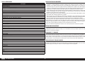
PRINTED COVERING NOTES
• The covering used on your model has the coloring and markings printed directly on the covering.
• The covering has a self-adhesive backing. Heat can be applied to shrink the covering, just not direct heat as this
will damage the covering. Use a covering iron on low and place a piece of parchment or covering backing between
the model and covering iron to disperse the heat. A heat gun can also be used to shrink the covering. Apply heat
sparingly (2-3 seconds) and use a glove to press the covering in convex curves.
• Use only mild cleaning agents on the printed fi nish. Denatured alcohol is the most aggressive agent we recommend,
but test on an inconspicuous area fi rst. Prolonged use will remove the printed detail.
• Use tape with care. Anything other than low-tack tape can remove the fi nish, particularly on edges.
• Avoid contact with raw fuel, especially alcohol-based fuels containing nitro methane. Prolonged exposure to fuel or
chemicals may damage to the printed covering.
• Remove exhaust residue as soon as practical to avoid staining or damaging of the fi nish.
There are two areas on your aircraft that will receive wear under normal use. The fi rst area is where the cowlings fi t
wing sections, and the sides of the nacelles. Placing the soft side of hook and loop tape inside the cowling will reduce
the wear on the covering in these areas. Sanding the inside of the cowling smooth will also help prevent wear of the
covering under the cowling.
Additional covering has been supplied with your model in case repairs are needed.
BUILDING PRECAUTIONS
Prepare the work surface prior to beginning the build. The surface should be soft and free of any sharp objects. We
recommend resting the airframe parts on a soft towel or pit mat to prevent scratching or denting the surface of the
aircraft.
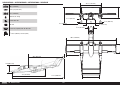
TRANSPORTATION AND STORAGE
Use the three-view drawing at the back of the manual to determine how much room will be required to transport
and store your model. We also recommend the use of wing and stabilizer bags to help protect these surfaces during
transport and storage. The control horns and linkages can cause damage to other surfaces even when placed in
storage bags. Always transport and store the wings and stabilizer so the linkages do not contact other panels to
prevent damage.
CHECKING BLIND NUTS
When building the aircraft, you will be required to thread machine screws into blind nuts. We recommend pre-threading
the screws to make sure the blind nuts are clear of any debris. If the screws do not thread in easily, clear the threads
using the appropriate tap and tap handle.

6EN
BUILDING CONSIDERATIONS
Servo Extensions
The OV-10 Bronco uses a large number of servos, and many servo extensions. Make sure to route these extensions
neatly, and label them at each connection to make assembly of the model at the fi eld go smoothly.
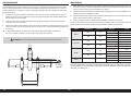
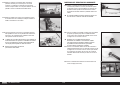
Radio Installation
This manual covers the installation for the receiver, receiver batteries and other components in the fuselage. The radio
can also be installed on the underside of the wing center section (photo shown in manual) to reduce the number of
extensions and connections when using gas engines. Feel free to mount these components in locations that best suit
your specifi c requirements.
EP Motors and ESCs
When installing the electric motor option, the ESC for each motor MUST be mounted near the battery. Long battery
leads will cause the ESC to operate incorrectly, or not at all. Keeping the battery-to-ESC leads as short as possible, and
using longer leads to the motors, is the correct installation for these components.
Hinging
The OV-10 Bronco requires a large number of hinges when assembled. The model can be assembled using the
methods shown in the manual, hinging each surface as the model is assembled using 30-minute epoxy. The hinges
can also be installed at the beginning of the build procedure using Aero Tech Epoxy, 50ml (DLMAD64). This is a slow
cure adhesive that can be applied directly into each of the hinge pockets. Make sure to use low-tack tape to hold each
control surface in position until the adhesive has fully cured. Although the process is the same, it is recommended to
read through the manual regarding the hinging process before using the Aero Tech epoxy.
Control Surface Locations
When removing the control surfaces from the fi xed surfaces, we recommend removing only one surface at a time, then
hinging it before removing the next control surface. If planning on removing all the control surfaces, use low-tack tape
to mark them so they can be returned to their correct locations. The covering is not symmetrical, and the trim scheme
will not align if a control surface is in the incorrect location.
Retract Module and the Optional Landing Gear Doors
The retract module is designed to operate up to three retracts and up to three landing gear door servos. The OV-10
Bronco uses six landing gear door servos, which will overload the retract module. The landing gear doors are optional,
and if they are installed, a computer radio that has a gear door sequencer must be used to connect and operate the
landing gear door servos.
A switch must be used between the battery and retract module. When the radio system is turned on, the retracts must
remain off so they do not cycle. Failure to follow this procedure may result in the retracts beginning their retraction
cycle before the radio is connected, which can lead to damage of the air frame (and gear doors if fi tted).
When connecting the retracts to the module, it may be necessary to rotate the plug on one (or more) of the retract
leads 180-degrees so the red (positive) of the retract lead is aligned with the negative (-) on the module. Check the
operation of the retracts, and make this change if necessary. This will not damage the retract.
Servo Arms
The use of a metal servo arm for the elevator servo is highly recommended. This is optional and at the builders
discretion, but due to the large size and importance of the elevator, we advise a metal arm for this surface.
Overall Assembly
Note that much of the assembly must be completed twice (rudder, aileron, engine/motor, etc.). In the case of the fl aps,
this section will be completed four times before continuing. Make sure to plan ahead for time it will take to assemble
this model.
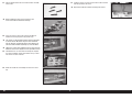
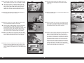
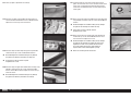
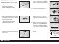
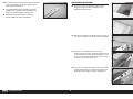
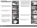
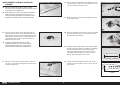
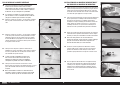
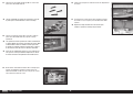
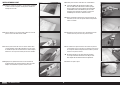
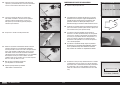
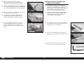
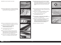
Do not mix any epoxy until instructed to do so.
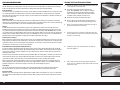
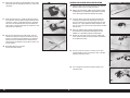
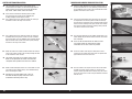
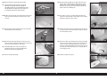
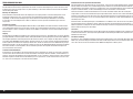
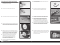
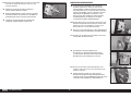
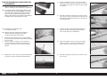
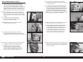
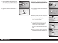
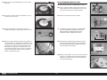
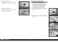
Use the short hinges for the ailerons. The longer hinges
are used for the flaps due to the hinging technique used.
2. Apply a small amount of oil to the fl ex point of the hinge to
prevent epoxy from entering the hinge.
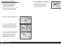
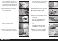
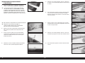
HINGING THE STABILIZER AND ELEVATOR
1. Separate the stabilizer and elevator. Remove the hinges and
set the stabilizer and elevator aside.
The hinges can also be installed using Aero Tech
Epoxy, 50ml (DLMAD64). This is a slow cure adhesive
applied directly into each of the hinge pockets. Make
sure to use low-tack tape to hold each control surface
in position until the adhesive has fully cured.
3. Insert the hinge so the center of the hinge point aligns with
the front edge of the bevel on the control surface. Check that
the hinge can move freely.
4. Position the hinge so it is perpendicular to the hinge line
when fully defl ected.
5. Mix 1/2 ounces (15mL) of 30-minute epoxy. Remove the
hinges, then use a toothpick to apply epoxy inside each of the
holes for the hinges.

7 EN
OV-10 Bronco 30cc
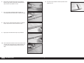
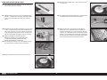
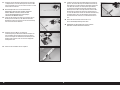
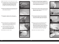
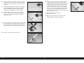
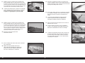
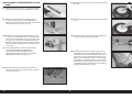
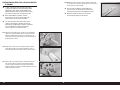
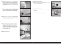
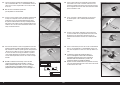
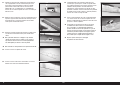
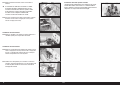
7. Use a paper towel and isopropyl alcohol to remove any
excess epoxy. Allow the epoxy to fully cure before proceeding.
6. Apply epoxy to the outside of the hinge using a toothpick.
Insert the hinges into the control surface after applying the
epoxy. Verify the hinge position is correct.
8. Mix 1/2 ounces (15mL) of 30-minute epoxy. Use a toothpick
to apply epoxy inside each of the holes for the hinges.
9. Apply epoxy to the outside of the hinge using a toothpick
10. Fit the elevator to the stabilizer. Check that the control surface
can move freely, and the hinges are all aligned properly. Use
a paper towel and isopropyl alcohol to remove any excess
epoxy.
11. Use low-tack tape to hold the elevator in position until the
epoxy fully cures.

8EN
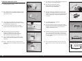
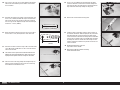
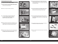
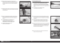
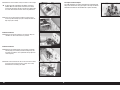
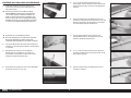
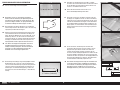
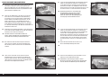
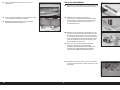
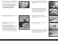
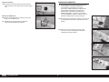
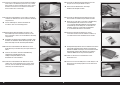
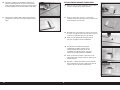
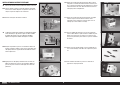
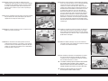
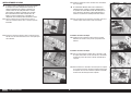
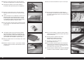
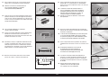
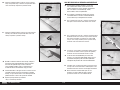
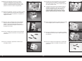
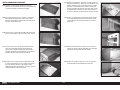
STABILIZER SERVO INSTALLATION
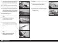
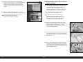
12. Remove the servo cover from the stabilizer. Leave the tape at
the leading edge as a reference.
13. Use a hobby knife with a #11 blade to remove the covering
for the servo arm, and to puncture the holes for the servo
cover mounting screws.
14. Fit the cover back in position. Use a drill and 1/16-inch
(1.5mm) drill bit to drill the four holes through the cover into
the stabilizer for the mounting screws.
Be careful not to apply too much pressure and drill
through the mount and through the top of the stabilizer.
The holes for the screws must be prepared as
outlined in the following steps. If they are not
prepared correctly, the screws could come loose in
flight, resulting in the loss of elevator control.
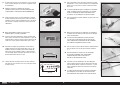
15. Use a #1 Phillips screwdriver to thread an M2 x 10 self-
tapping screw into each hole. Remove the screws before
proceeding.
16. Apply 2–3 drops of thin CA into each hole to harden the
threads made by the screws. Allow the CA to fully cure before
proceeding.
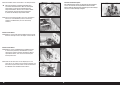
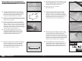
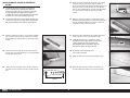
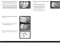
2
3
/
4
inches (70mm)
13/16 inch
(21mm)
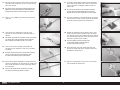
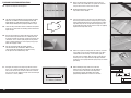
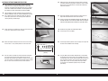
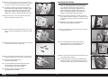
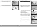
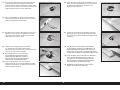
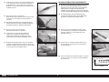
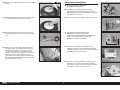
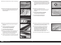
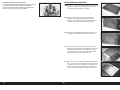
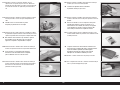
17. Use a drill and 1/16-inch (1.5mm) drill bit to drill through the
laser cut holes in the elevator servo mount.
Use servo with a minimum of 350 oz-in
for the elevator servo. We recommend the
Spektrum A6310 servo (SPMSA6310)
18. Prepare the holes for the elevator screws using the same
technique as the elevator servo cover screws. Secure the
elevator servo in position using the screws provided with the
servo. The output for the servo will face toward the front of
the stabilizer.
It is recommended to use a metal servo
arm for the elevator servo.
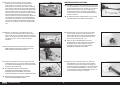
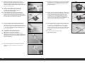
19. Center the elevator servo using the radio system. Position
the servo arm on the servo so it is perpendicular to the servo
centerline. Secure the servo arm to the servo using the
hardware provided with the servo.
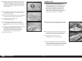
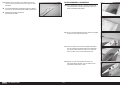
20. Assemble the linkage for the elevator using two rod ends and
the 1
5
/
8
inch (41mm) threaded rod. Snap an aluminum ball
into each of the rod ends. Thread each ball end a minimum
of 12 turns on the link. Adjust so the overall length measures
2
3
/
4
inches (70mm).
21. When attaching the linkage to the servo arm, use the hole
in the arm that is 13/16-inch (21mm) from the center of the
arm.

9 EN
OV-10 Bronco 30cc
22. Attach the link to the servo arm using an M3 x 15 button head
screw, M3 washer and M3 Lock nut. Use a 2mm hex wrench
and 5.5mm nut driver.
The washer must be placed on the outside of the ball link,
opposite the servo arm. Omitting this could allow the ball
to pop out of the plastic ball link causing loss of control.
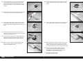
23. Secure a 12-inch (300mm) servo extension to the elevator
servo lead.
24. Tie the string in the stabilizer to the end of the servo
extension. Use the string to pull the extension through the
stabilizer.
The elevator servo lead can be routed in either nacelle. Make
sure to note which side the extension exits the stabilizer
when installing the elevator extension in the nacelle.
25. Secure the servo cover in position using four M2 x 10
self-tapping screws. Tighten the screws using a #1 Phillips
screwdriver.
To further spread the load on the elevator servo mounting
screws, we advise the used of small washers under
the heads of the mounting screws (not included).
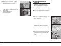
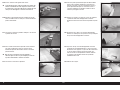
26. Run your fi nger along the bottom of the elevator to locate the
area for the control horns near the pushrod. Use a hobby knife
and #11 blade to remove the covering, exposing the slots for
the control horns.
There are two sets of slots for control horns, so make
sure the ones selected align with the pushrod.
27. Use medium-grit sandpaper to lightly sand the control horn
where it fi ts into the control surface. Clean the sanded area
using a paper towel and isopropyl alcohol to remove any
debris or oils.
Use tape on the painted area to help prevent removing
the paint from the exposed portion of the control horn.
Remove the tape once the control horn has been sanded.
29. Remove the control horns from the control surfaces. Insert
the M3 x 15 button head screw into the hole in the control
horn. Remove any paint using a hobby knife and #11 blade so
the screw fi ts into the hole easily. Place an M3 locknut on the
end of the screw but leave the nut loose.
The hole should be just large enough for the
screw to slide through, yet still fit snugly in
the hole and not move excessively.
28. Test fi t the control horns in the slots. Do not force the control
horn into the slot. Use low-tack tape around the control horns
to prevent epoxy from getting on the control surface.
30. Apply epoxy to the area of the control horn that fi ts into
the slot. Use enough epoxy so the control horn will be fully
bonded to the control surfaces.
31. Make sure to apply epoxy to all the surfaces of the control
horn that fi t into the control surface.

10EN
32. Apply epoxy to the slots in the elevator. Make sure the epoxy
gets into the slots for a good bond between the surfaces and
control horn.
33. Before the epoxy fully cures, remove the tape from around
the control horn. This will allow the epoxy to fl ow around the
control horn, creating a small fi llet between the control horn
and surface for a fi nished look and secure bond. Allow the
epoxy to fully cure before proceeding, then remove the screw
and nut from the control horn.
34. With the servo connected to the radio system, center the
elevator servo. Attach the linkage to the control horn using
the M3 x 15 button head screw and M3 lock nut. Adjust the
linkage to center the elevator. Once the linkage has been
adjusted, tighten the hardware using an M3 hex wrench and
5.5mm nut driver.
Do not over-tighten this screw as it
may result in excess friction.
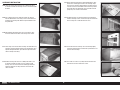
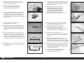
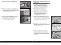
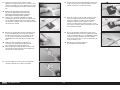
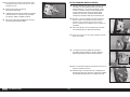
AILERON AND AILERON SERVO INSTALLATION
35. Hinge the aileron using the same technique as the stabilizer.
Allow the epoxy to fully cure before proceeding.
Make sure to label aileron, rudder and flap surfaces before
removing them as it is possible to swap locations resulting
in the covering and control horn locations not aligning.
36. Center the aileron servo using the radio system. With the
servo output facing toward the leading edge of the wing,
place the servo arm on the servo perpendicular to the servo,
rotate the arm 1 spline toward the trailing edge of the wing,
then secure the arm to the servo using the hardware included
with the servo.
Due to the geometry of the partially enclosed pushrod,
the servo arms are not centered at 90 degrees as they
would be in a conventional external pushrod system.
38. Place the servo in the mounts in the wing. Use the servo
cover to position the servo as close to the cover as possible,
without it contacting the cover.
39. Use a felt-tipped pen to mark the locations for the servo
mounting screws.
37. Remove the cover for the aileron servo. Use a hobby knife
and #11 blade to remove the covering from the pushrod exit
on the bottom of the wing.

11 EN
OV-10 Bronco 30cc
5
1
/
2
inches (140mm)
1 inch
(25mm)
40. Use a pin vise and 1/16-inch (1.5mm) drill bit to drill the four
holes for the servo mounting screws. Make sure to harden
the screw holes.
41. Assemble the linkage for the aileron using two rod ends and
the 4
1
/
2
inch (114mm) threaded rod. Snap an aluminum ball
into each of the rod ends. Thread each ball end a minimum
of 12 turns on the link. Adjust the length so the overall length
measures 5
1
/
2
inches (140mm).
42. When attaching the linkage to the servo arm, use the hole in
the arm that is 1-inch (25mm) from the center of the arm.
44. Place the servo in the wing, guiding the linkage through the
opening near the aileron hinge line. Secure the servo using
the hardware included with the servo.
43. Attach the link to the servo arm using an M3 x 15 button head
screw, M3 washer and M3 Lock nut. Use a 2mm hex wrench
and 5.5mm nut driver.
The washer must be placed on the outside of the ball link,
opposite the servo arm. Omitting this could cause the ball
to pop out of the plastic ball link, causing loss of control.
45. Secure a 12-inch (300mm) servo extension to the aileron
servo lead. Route the servo lead and extension through the
tube inside the wing. The lead will exit in the opening for the
fl ap servo before continuing through the wing panel.
46. Retrieve the servo lead from the wing panel.
47. Install the aileron control horn using the same technique as
the elevator control horn. Allow the epoxy to fully cure before
proceeding. With the servo connected to the radio system,
center the aileron servo. Attach the linkage to the control horn
using an M3 x 15 button head screw and M3 lock nut. Adjust
the linkage to center the aileron. Once the linkage has been
adjusted, tighten the hardware using an M3 hex wrench and
5.5mm nut driver.
Do not over-tighten this screw as it
may result in excess friction.
Repeat this section to install the remaining
aileron and aileron servo.

12EN
5
1
/
2
inches (140mm)
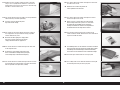
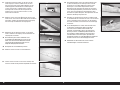
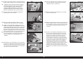
FLAP AND FLAP SERVO INSTALLATION
48. Separate the fl ap from the wing panel.
The flaps must be positioned to the wing before the epoxy
begins to cure. Make sure to read through all the steps
before mixing any epoxy. Glue only one flap at a time to
allow enough working time to properly install the hinges.
49. Locate the fl ap control horns. When installed, the fl at portion
of the horn (as indicated in the drawing) will face toward the
top of the fl aps.
50. Run your fi nger down the leading edge of the fl ap to locate
the area for the fl ap control horns. Use a hobby knife and
#11 blade to remove the covering, exposing the slots for the
control horn. Use 15-minute epoxy to glue the fl ap control
horns in position. Remove any excess epoxy using a paper
towel and isopropyl alcohol.
Use the steps outlined for the elevator control
horn to install the flap control horns. Make sure to
check that the flap control horns are glued securely
in the flaps once the adhesive fully cures.
51. Assemble the linkage for the fl ap using two rod ends and
the 4
1
/
2
inch (114mm) threaded rod. Snap an aluminum ball
into each of the rod ends. Thread each ball end a minimum
of 12 turns on the link. Adjust the length so the overall length
measures 5
1
/
2
inches (140mm).
52. Attach the linkage to the control horn using an M3 x 15
button head screw and M3 lock nut. Tighten the hardware
using an M3 hex wrench and 5.5mm nut driver.
Do not over-tighten this screw as it
may result in excess friction.
53. Insert the long hinges in the fl aps. Check the fi t of the fl ap
to the wing. It will fi t centered in the opening. The hinge pin
will be positioned directly over the gap between the leading
edge of the fl ap and the aft edge of the wing opening. Test
the operation of the fl ap to make sure the hinges are properly
aligned and the fl ap moves freely.
When installing the flap servos, the servo arms
will all face the same direction. This will allow the
use of a Y-harness to connect all the flap servos.
This mounting system also allows easier radio
programming radio when a Y-harness is not used.
54. Make sure to guide the linkage over the servo tray as shown
in the photo so it can be connected to the fl ap servo. Once
satisfi ed with the fi t of the fl ap, use 30-minute epoxy to
glue the hinges in position. Glue the hinges in both the fl ap
and wing, then use a paper towel and isopropyl alcohol to
remove any excess epoxy. Allow the epoxy to fully cure before
proceeding.

13 EN
OV-10 Bronco 30cc
55. Secure the fl ap servo in the servo tray using the hardware
included with the servo. The output of the servo will face
toward the trailing edge of the wing. Make sure to prepare
the holes in the servo tray using thin CA before the servo is
installed.
56. Pull the fl ap and aileron servo leads through the wing. Make
sure to mark the leads so they can be easily identifi ed.
57. Center the fl ap servo. Place the servo arm on the servo so it
is perpendicular to the servo centerline. Remove any arms
that may interfere with the operation of the servo using side
cutters.
58. Attach the fl ap linkage to the servo arm using an M3 x 15
button head screw, M3 washer and M3 Lock nut. Use a 2mm
hex wrench and 5.5mm nut driver.
The washer must be placed on the outside of the ball link,
opposite the servo arm. Omitting this could allow the ball
to pop out of the plastic ball link causing loss of control.
59. Adjust the linkage to achieve the mid fl ap position of 30˚.
Once set, secure the servo arm to the servo using the
hardware included with the servo.
60. Use the radio or servo tester to move the fl ap to the up fl ap
position. Use the travel settings in the radio to set the fl ap
position
61. Use the radio to move the fl ap to the full fl ap position of 80˚.
Use the travel settings in the radio to set the fl ap position
When installing the remaining flap servos, attach the servo
arm perpendicular to the servo center line in the mid flap
position. The linkage must be adjusted when the servo is in
the up flap position so the flaps are aligned correctly in flight.
Take care not to over-travel the servos, as there is a
mechanical limit for both up and down flap positions.
Overloading the servos against these limits will result
in damage to the servos or control surfaces.
Repeat this section to install the
remaining flaps and flap servos.

14EN
CENTER SECTION SERVO LEADS
The servo leads that are in the center section can be
installed at this time. Make sure to install enough leads to
properly connect all the servos. These leads will include
flap, aileron, rudder, throttle, choke and elevator.
If the receiver is mounted in the wing center section
for a gas engine, the use of 24-inch (610mm) will
be long enough to connect to the receiver.
62. Use a hobby knife and #11 blade to remove the covering in
the bottom center of the wing center section
63. Use a hobby knife and #11 blade to remove the covering in
the bottom of the wing center section near each end of the
wing panel. Route a 36-inch (900mm) servo extension for the
fl ap and aileron servos (servos in the outer panels) through
the tubes in the wing center section.
64. Route the leads for the rudder, elevator, throttle and choke (if
using a gas engine) (servos in the nacelles) through the holes
in the ends of the center section.
The elevator servo lead can be routed in either nacelle.
Make sure the position of the elevator servo extension
corresponds to the position of the lead in the stabilizer.
65. Route all leads through the hole in the center. Make sure that
each lead has been labeled so they can be identifi ed easily
when assembling the model.
Attaching the plug ends together with a zip tie or
thin hook and loop strap helps reduce the chance
of individual leads falling into the wing.
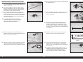
RUDDER AND RUDDER SERVO INSTALLATION
66. Hinge the rudder following the processes outlined earlier in
the manual. Guide the 35
1
/
2
inch (902mm) pushrod through
the pushrod tube in the nacelle. The pushrod will be located
opposite each other on each nacelle.
67. Insert the pushrod into the tube and gently press it to make
an impression on the covering where it exits the fuselage.
This will leave an impression in the covering to help indicate
where to cut the covering for the push rod exit. Use a hobby
knife and #11 blade to remove the covering so the pushrod
can exit the nacelle near the rudder.
68. Use 30-minute epoxy to glue the rudder control horns in the
rudder. Follow the procedures outlined earlier for the control
horn installation.
There are slots on both sides of the rudder, so make
sure to only remove the covering for the rudder
control horns on the same side as the pushrod.
69. Center the rudder servo using the radio system. Place a
servo arm on the rudder servo so the arms are parallel and
perpendicular to the servo center line.
70. Place the rudder in the tray on the same side as the rudder
pushrod. Using side cutters, remove any arms that may
interfere with the operation of the linkage using side cutters.
Secure the servo in the nacelle using the hardware included
with the servo.

15 EN
OV-10 Bronco 30cc
71. Snap an aluminum ball into the ball end. Thread the ball end
a minimum of 12 turns on the rudder pushrod. Attach the ball
end to the servo arm using an M3 x 15 button head screw,
M3 washer and M3 Lock nut. Use a 2mm hex wrench and
5.5mm nut driver.
The washer must be placed on the outside of the ball link,
opposite the servo arm. Omitting this could cause the ball
to pop out of the plastic ball link causing loss of control.
72. Snap an aluminum ball into the ball end. Thread the ball end
a minimum of 12 turns on the rudder pushrod. Attach the ball
end to the control horn using an M3 x 15 button head screw
and M3 lock nut. Adjust the linkage to center the rudder. Once
the linkage has been adjusted, tighten the hardware using an
M3 hex wrench and 5.5mm nut driver.
Do not over-tighten this screw as it
may result in excess friction.
73. Remove the covering in the fi n to expose the mount for the
stabilizer.
Repeat the previous steps in this section for
the rudder and rudder servo installation, and
to remove the covering for the stabilizer.
74. Connect a 48 inch and 12 inch servo extension for the
elevator servo. Use tape to secure the extensions. Wrap the
tape as shown, as this will help guide the extension through
the nacelle.
75. Tape the string to the end of the elevator extension. Wrap the
tape on the string as shown to help the extension through the
nacelle.
The elevator servo lead can be routed in either nacelle.
Make sure the position of the lead corresponds
to the position of the lead in the stabilizer.
76. Use the string to carefully pull the elevator servo lead through
the nacelle.
There are areas where the lead must make turns that
could cause it to get stuck, so work carefully not to
accidentally disconnect the string or extensions.
77. The elevator extension can be retrieved inside the nacelle
near the rudder pushrod. We recommend tying the lead
around one of the formers so it can be ready when
assembling the model.

16EN
1 inch
(25mm)
OPTIONAL RETRACT DOOR INSTALLATION
The installation of the retract doors is optional and will
require the use of a computer radio that has a gear door
sequencer. A separate gear door sequencer unit can also be
used. The included retract controller is not compatible with
the number of servos required for this particular model.
The gear doors are purely cosmetic and have no effect on
how the model flies. They can also be retrofitted at any time.
79. Center the retract gear door servo. Place the servo arm on the
servo so it is parallel to the servo centerline.
80. When attaching the linkage to the servo arm, use the hole in
the arm that is 1 inch (25mm) from the center of the arm.
81. Use side cutters to remove the arm that extends away from
the servo, keeping the arm that extends over the servo.
Assemble the link for the gear door, then attach it to the servo
arm using an M3 x 15 button head screw, M3 washer and M3
lock nut. Use a 2mm hex wrench and 5.5mm nut driver.
78. Use a hobby knife and #11 blade to remove the covering
for the nose gear retract in the fuselage. Also remove the
covering for the gear door hinges.
82. Mount the servo in the opening. The holes for the servo will
need to be drilled and prepared as outlined in earlier sections
of this manual. The output of the servo will face toward the
front of the airframe.
83. Repeat the previous steps to mount the second servo. The
output will mount toward the front of the airframe.
Using a Y-harness will not work to operate the gear doors, as
one door will open as the other gear door closes. A computer
radio must be programmed to operate the gear door servos.
Do not mix any epoxy until instructed to do so.
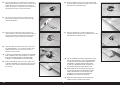
84. Fit the hinges in the gear doors.
85. Fit the hinges into the pockets in the fuselage. The hinges will
be fl ush with the bottom of the fuselage.
86. The gear doors will need to be adjusted to be centered over
the opening for the retract. A thin ruler or hobby knife can be
used to make small changes to their position. Once the fi t has
been checked, the hinges can be secured using 30-minute
epoxy. Make sure to check the position of the gear doors
as the epoxy cures. Allow the epoxy to fully cure before
proceeding.

17 EN
OV-10 Bronco 30cc
87. Attach the linkage to the gear door using the M3 x 15 button
head screw. Tighten the screw using a 2mm hex wrench. Use
the radio system to set the throw of the servo to open and
close the gear door.
It is essential that the servos are not over travelling and
loading the servos in either up or down positions. We advise
finding out where the mechanical stop is in the in the up and
down position and backing off the servo travel a few percent
in either position. A slight gap when closed, or less than a 90
degree angle when open, is better than damaging the servos.
Repeat this section to install the remaining
gear doors and servos.
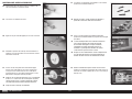
MAIN GEAR RETRACT INSTALLATION
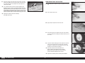
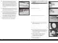
88. Use small pliers to snap the e-clip in the groove for the gear
axle.
89. Slide a washer on the axle.
90. Apply a drop of light machine oil on the axle.
91. Check the opening in the wheel for any burrs and remove if
necessary. Slide the axle through the wheel. Slide the spacer
on the axle.
92. Fit the axle into the landing gear strut. Tighten the setscrew
using a 2mm hex wrench to secure the axle. Check that
the wheel can rotate freely. If not, determine the cause for
binding and correct before proceeding.
Check for a flat spot at the end of the axle. If
there is not one, then make one using a flat file.
Not having the flat will allow the setscrew will slip
and the axle/wheel falling out of the aircraft.
Prepare the remaining retract assembly for installation.

18EN
93. Slide an M4 lock washer on each of the four M4 x 25 button
head screws.
When installing the retract in the nacelle, the strut
for the retract will face toward the fuselage.
94. Secure the retract in the nacelle using the four M4 x 25
button head screws prepared in the previous step.
The retracts can be operated manually using the test button
on the retract box. We advise using the retract module to
test the retraction and extension of the retract with the leg
and wheel attached before tightening any of the hardware.
Tighten the screws evenly. Tightening one at a time fully may
distort the retract frame slightly and cause operational issues.
95. Four M4 lock nuts are used inside the fuselage to complete
the retract installation. Tighten the hardware using a 2.5mm
hex wrench and 7mm nut driver.
96. Route the lead for the servo through the hole in the retract
bay.
97. Inside the nacelle, secure the retract lead so it won’t interfere
with the operation of the retract.
Repeat this section to install the remaining main retract.

19 EN
OV-10 Bronco 30cc
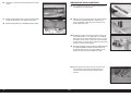
NOSE GEAR RETRACT INSTALLATION
98. Use a hobby knife and #11 blade to remove the covering for
the nose gear retract in the fuselage.
99. Mount the steering servo in the retract servo opening using
four M3 x 12 button head screws. Apply a drop of threadlock
on each screw, then tighten the screws using a 2mm hex
wrench.
101. Use small pliers to snap the e-clip in the groove in the nose
gear axle. Slide the axle into the nose gear wheel fork.
100. Assemble the steering linkage and attach it to the servo using
an M3 x 15 button head screw, M3 washer and M3 lock nut.
Use a 2mm hex wrench and 5.5mm nut driver. Snap the ball
on the steering arm of the retract. Center the steering servo
and adjust the length of the linkage to center the nose gear.
Make sure to adjust the servo travel so equal
defection is achieved in each direction. Also make
sure the servo is not over traveling as this may
damage the ball attached to the nose leg.
102. Apply a drop of light machine oil in the hole in the wheel.
103. Slide the wheel in position, then use the remaining e-clip to
secure the axle.
104. The completed assembly for the nose gear can be mounted in
the fuselage one the servo and wheel are installed.
105. Mount the nose gear in the fuselage using four M4 x 25
button head screws, an M4 lock washer and M4 lock nut.
Tighten the hardware using a 2.5mm hex wrench and 7mm
nut driver. Use a rubber band across the sides of the fuselage
to apply a very small amount of tension of the steering servo
lead. This will keep the lead from accidentally getting into the
retract mechanism during the operation of the retract.

20EN
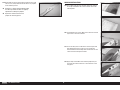
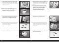
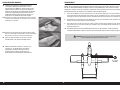
6
5
/
8
inches (169mm)
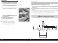
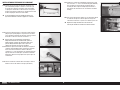
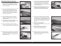
ELECTRIC MOTOR INSTALLATION
Skip this section when installing gas engines.
106. Attach the mount to the motor using the hardware included
with the motor. Use a drop of threadlock on each screw to
prevent them from vibrating loose.
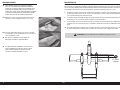
107. Measure the length of the motor and record it.
108. Mark the position of the fi rewall on the motor box so it can
be positioned after the epoxy has been applied. Remove the
bottom support from the motor box before proceeding.
109. Apply 30-minute epoxy to the areas of the motor box where
the fi rewall will be positioned. Slide the fi rewall in position
and allow the epoxy to cure before proceeding
The required length of the motor and motor mount
is 6
5
/
8
inches (169mm). Position the firewall in
the motor box so the length of the box, plus the
length of the motor, total this dimension.
110. Use 30-minute epoxy to glue the triangle stock inside the
motor box against the fi rewall. The triangle stock will require
trimming to fi t tightly in the corners. Allow the epoxy to fully
cure before proceeding.
111. Use 30-minute epoxy to glue the bottom support in position.
Make sure to glue triangle stock under the brace at the
fi rewall and the mount that fi ts against the fuselage.
112. Place the mounting template on the fi rewall. Use low-tack
tape to hold the template in position. Use a drill and 7/32-inch
(5.5mm) drill bit to drill the four holes in the fi rewall to attach
the motor box.
114. Attach the motor box to the fi rewall using the screws from the
previous step.
113. Slide an M5 lock washer, then an M5 washer on the M5 x 25
socket head screw. Prepare all four screws.
La pagina sta caricando ...
La pagina sta caricando ...
La pagina sta caricando ...
La pagina sta caricando ...
La pagina sta caricando ...
La pagina sta caricando ...
La pagina sta caricando ...
La pagina sta caricando ...
La pagina sta caricando ...
La pagina sta caricando ...
La pagina sta caricando ...
La pagina sta caricando ...
La pagina sta caricando ...
La pagina sta caricando ...
La pagina sta caricando ...
La pagina sta caricando ...
La pagina sta caricando ...
La pagina sta caricando ...
La pagina sta caricando ...
La pagina sta caricando ...
La pagina sta caricando ...
La pagina sta caricando ...
La pagina sta caricando ...
La pagina sta caricando ...
La pagina sta caricando ...
La pagina sta caricando ...
La pagina sta caricando ...
La pagina sta caricando ...
La pagina sta caricando ...
La pagina sta caricando ...
La pagina sta caricando ...
La pagina sta caricando ...
La pagina sta caricando ...
La pagina sta caricando ...
La pagina sta caricando ...
La pagina sta caricando ...
La pagina sta caricando ...
La pagina sta caricando ...
La pagina sta caricando ...
La pagina sta caricando ...
La pagina sta caricando ...
La pagina sta caricando ...
La pagina sta caricando ...
La pagina sta caricando ...
La pagina sta caricando ...
La pagina sta caricando ...
La pagina sta caricando ...
La pagina sta caricando ...
La pagina sta caricando ...
La pagina sta caricando ...
La pagina sta caricando ...
La pagina sta caricando ...
La pagina sta caricando ...
La pagina sta caricando ...
La pagina sta caricando ...
La pagina sta caricando ...
La pagina sta caricando ...
La pagina sta caricando ...
La pagina sta caricando ...
La pagina sta caricando ...
La pagina sta caricando ...
La pagina sta caricando ...
La pagina sta caricando ...
La pagina sta caricando ...
La pagina sta caricando ...
La pagina sta caricando ...
La pagina sta caricando ...
La pagina sta caricando ...
La pagina sta caricando ...
La pagina sta caricando ...
La pagina sta caricando ...
La pagina sta caricando ...
La pagina sta caricando ...
La pagina sta caricando ...
La pagina sta caricando ...
La pagina sta caricando ...
La pagina sta caricando ...
La pagina sta caricando ...
La pagina sta caricando ...
La pagina sta caricando ...
La pagina sta caricando ...
La pagina sta caricando ...
La pagina sta caricando ...
La pagina sta caricando ...
La pagina sta caricando ...
La pagina sta caricando ...
La pagina sta caricando ...
La pagina sta caricando ...
La pagina sta caricando ...
La pagina sta caricando ...
La pagina sta caricando ...
La pagina sta caricando ...
La pagina sta caricando ...
La pagina sta caricando ...
La pagina sta caricando ...
La pagina sta caricando ...
La pagina sta caricando ...
La pagina sta caricando ...
La pagina sta caricando ...
La pagina sta caricando ...
La pagina sta caricando ...
La pagina sta caricando ...
La pagina sta caricando ...
La pagina sta caricando ...
La pagina sta caricando ...
La pagina sta caricando ...
La pagina sta caricando ...
La pagina sta caricando ...
La pagina sta caricando ...
La pagina sta caricando ...
La pagina sta caricando ...
La pagina sta caricando ...
La pagina sta caricando ...
La pagina sta caricando ...
La pagina sta caricando ...
La pagina sta caricando ...
La pagina sta caricando ...
La pagina sta caricando ...
La pagina sta caricando ...
La pagina sta caricando ...
La pagina sta caricando ...
La pagina sta caricando ...
La pagina sta caricando ...
La pagina sta caricando ...
-
 1
1
-
 2
2
-
 3
3
-
 4
4
-
 5
5
-
 6
6
-
 7
7
-
 8
8
-
 9
9
-
 10
10
-
 11
11
-
 12
12
-
 13
13
-
 14
14
-
 15
15
-
 16
16
-
 17
17
-
 18
18
-
 19
19
-
 20
20
-
 21
21
-
 22
22
-
 23
23
-
 24
24
-
 25
25
-
 26
26
-
 27
27
-
 28
28
-
 29
29
-
 30
30
-
 31
31
-
 32
32
-
 33
33
-
 34
34
-
 35
35
-
 36
36
-
 37
37
-
 38
38
-
 39
39
-
 40
40
-
 41
41
-
 42
42
-
 43
43
-
 44
44
-
 45
45
-
 46
46
-
 47
47
-
 48
48
-
 49
49
-
 50
50
-
 51
51
-
 52
52
-
 53
53
-
 54
54
-
 55
55
-
 56
56
-
 57
57
-
 58
58
-
 59
59
-
 60
60
-
 61
61
-
 62
62
-
 63
63
-
 64
64
-
 65
65
-
 66
66
-
 67
67
-
 68
68
-
 69
69
-
 70
70
-
 71
71
-
 72
72
-
 73
73
-
 74
74
-
 75
75
-
 76
76
-
 77
77
-
 78
78
-
 79
79
-
 80
80
-
 81
81
-
 82
82
-
 83
83
-
 84
84
-
 85
85
-
 86
86
-
 87
87
-
 88
88
-
 89
89
-
 90
90
-
 91
91
-
 92
92
-
 93
93
-
 94
94
-
 95
95
-
 96
96
-
 97
97
-
 98
98
-
 99
99
-
 100
100
-
 101
101
-
 102
102
-
 103
103
-
 104
104
-
 105
105
-
 106
106
-
 107
107
-
 108
108
-
 109
109
-
 110
110
-
 111
111
-
 112
112
-
 113
113
-
 114
114
-
 115
115
-
 116
116
-
 117
117
-
 118
118
-
 119
119
-
 120
120
-
 121
121
-
 122
122
-
 123
123
-
 124
124
-
 125
125
-
 126
126
-
 127
127
-
 128
128
-
 129
129
-
 130
130
-
 131
131
-
 132
132
-
 133
133
-
 134
134
-
 135
135
-
 136
136
-
 137
137
-
 138
138
-
 139
139
-
 140
140
-
 141
141
-
 142
142
-
 143
143
-
 144
144


Hangar 9 HAN4670 Manuale del proprietario
- Categoria
- Giocattoli telecomandati
- Tipo
- Manuale del proprietario
- Questo manuale è adatto anche per
in altre lingue
- English: Hangar 9 HAN4670 Owner's manual
- français: Hangar 9 HAN4670 Le manuel du propriétaire
- Deutsch: Hangar 9 HAN4670 Bedienungsanleitung
Documenti correlati
-
 Hangar 9 HAN5280 Manuale del proprietario
-
 Hangar 9 HAN3390 Manuale utente
-
Evolution 33cc Manuale del proprietario
-
 Hangar 9 HAN4720CR Manuale del proprietario
-
 Hangar 9 HAN2990 Manuale del proprietario
-
 Hangar 9 HAN2820 Manuale del proprietario
-
 Hangar 9 HAN2765 Manuale del proprietario
-
 Hangar 9 HAN4770 Manuale del proprietario
-
 Hangar 9 HAN2890 Manuale del proprietario
-
 Hangar 9 HAN2530 Manuale del proprietario


Altri documenti
-
Evolution EVOE10GX Manuale utente
-
E-flite Habu 32x DF Manuale utente
-
Kyosho 11892 Manuale utente
-
Spektrum SPMSA6380 Manuale del proprietario
-
-
Spektrum SPMAS3000 Manuale del proprietario
-
-
DeLOCK 60243 Scheda dati
-
-