Videx 6286 Manuale utente
- Categoria
- Impianti citofonici
- Tipo
- Manuale utente

66251130-EN - V1.4 - 30/06/16
1
6200 Series
Art.6286 - Installation instructions
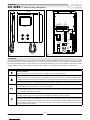
Art.6286 3.5" colour display videophone
27 mm 144 mm
182 mm
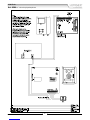
Fig. 1
SW
BUS1
BUS2
GND
+12VM
GND
+VAUX
C
NO
-DOL
+DOL
AL-LB GND
LB
AL
678
1235
4
ON
SW1
1234
ON
SW3
6 7 8
1235
4
ON
SW1
1234
ON
SW3
PT3 PT2
VR1
PT1
SW1
Fig. 2
DESCRIPTION
An intelligent Videophone using 3.5” full colour active matrix LCD monitor for VX2300. Including 4 buttons “service”, “privacy/bus
relay activation”, “door- open/intercommunicating call” and “camera recall” plus 3 LED’s for visual indication of all functions. Adjust-
ments & programmable options: call tone volume on 3 levels (low, medium, high), picture hue, brightness and contrast, call tone
melody, number of rings, privacy duration and address. Also includes a local bell function. The Art.6286 is surface mount.
PUSH BUTTONS, LEDS AND CONTROLS FIG. 1
Service push button.
When pressed it links internally the terminals “C” and “NO” on the connection terminals.
Privacy ON-OFF push button.
To enable the function press this button when the videophone is in stand-by. The service is automatically disabled when
the programmed time expires (the privacy duration time can be programmed) or manually by pressing again the button.
Activate bus relay board Art.2305 push button.
To activate a bus relay, during a conversation, press this button quickly as many times as the address value of the relay.
Door open push button.
Press this button to open the door when you are in conversation.
Intercommunication push button.
For an intercommunicating call, pick up the handset and press as many times as the extension or address value to
call (see SW3 Intercommunication Settings).
Camera recall push button.
Pick up the handset and press as many times as the DEVICE N. of the door station to switch on.
Camera switch push button.
If the door station uses the Art.4303N plus the Art.4330N, pressing this button during a conversation switches the
video signal coming from the camera module to the video signal coming from the caMera module input for external
camera. During the conversation, press and keep pressed the button until the camera switches. Repeat the opera-
tion to switch back to main camera.

66251130-EN - V1.4 - 30/06/16
2
6200 Series
Art.6286 - Installation instructions
PUSH BUTTONS, LEDS AND CONTROLS FIG. 1
LED Privacy on LED.
It illuminates when the privacy service is enabled.
LED Generic use LED.
It is controlled from the terminals “+DOL” and “-DOL”. Normally used to signal the door status (open or closed).
LED On LED.
It illuminates when the videophone is switched ON.
- SW1 Call tone volume control (3 levels).
- PT1 Brightness control (sliding wheel).
PT2 Colour intensity control trimmer (rotate left to increase or right to decrease).
PT3 Contrast control trimmer (rotate left to increase or right to decrease).
VR1 Microphone volume control trimmer (rotate left to increase or right to decrease).
SW Bus termination switch (Right position = BUS termination active, Left position = BUS termination disabled)
PROGRAMMING
The videophone setup consists of the following settings:
• Number of Rings;
• Melody selection;
• Privacy duration;
• Unit address (1..127, switches 1 to 7 of SW1);
• Bus Termination (open or close, switch SW);
• Intercommunication mode (between apartments or within apartment, switch 1 of SW3);
• Extension address (1..4, switches 2,3 of SW3);
• Slave mode (switch 4 of SW3).
The programming of the number of rings, melody and privacy duration are carried out through the videophone push buttons, all
other settings are carried out on the two dip-switch banks (SW1 and SW3) on the rear side of the video monitor (all the settings can
be done without opening the videophone).
It is necessary to remove temporary the power supply after making any programming changes.
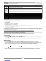
NUMBER OF RINGS, MELODY SELECTION AND PRIVACY DURATION
To make these changes, it is necessary to pick up the handset rst when the system is in stand-by.
NUMBER OF RINGS
• Keep pressed the button until the two LEDs and switch on.
• Press the button for the number of times corresponding to the required number of rings to set. A beep conrms each time
the button is pressed.
• Once the required number of rings is reached, wait approx 5 seconds for the two LED’s to switch o. The new value is stored.
MELODY SELECTION
• Keep pressed the button until the two LEDs and switch on. The unit emits the current selected melody.
• Press the button and keep it pressed to listen the next melody. Repeat the operation until the required melody is found.
• Once the required melody is found, wait approx 5 seconds for the two LED’s to switch o. The new melody is set.
PRIVACY DURATION
• Keep pressed the button until the two LEDs and are switched on.
• Press the button for the number of times corresponding to the required privacy duration to set. Each time the button is
pressed, the duration is increased by 15 minutes: i.e. to set 2 hours, press the button 8 times.
• Once the required privacy time is reached, wait approx 5 seconds for the two LED’s to switch o. The new duration is set.
Art.6286 3.5" colour display videophone

66251130-EN - V1.4 - 30/06/16
3
6200 Series
Art.6286 - Installation instructions
Art.6286 3.5" colour display videophone
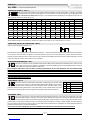
VIDEOPHONE ADDRESS SW1.1..7
SW1.1..7
The table below shows how to set the address of the videophone. Considering that ON = 1 and OFF = 0, multiply
each digit for the relevant decimal weight then sum values obtained to get the address: E.g. as highlighted in the
table OFF,ON,OFF,OFF,ON, OFF,ON in binary is equal to 0100101 then multiplying each digit for the relevant dec-
imal weight you obtain the address that is 37.
SWITCHES STATUS BINARY CODE DECIMAL WEIGHT ADDRESS
76543216432168421
OFF OFF OFF OFF OFF OFF ON 0 0 0 0 0 0 1 1
OFF OFF OFF OFF OFF ON OFF 0 0 0 0 0 1 0 2
OFF OFF OFF OFF OFF ON ON 0 0 0 0 0 1 1 3
OFF OFF OFF OFF ON OFF OFF 0 0 0 0 1 0 0 4
OFF ON OFF OFF ON OFF ON 0 1 0 0 1 0 1 37
ON ON ON ON ON ON ON 1 1 1 1 1 1 1 127
Note
The maximum number of units allowed is 100 but the address of each unit can be a value between 1 and 127.
VIDEOPHONE END OF LINE TERMIANTION SWCH1
Looking at the videophone from the rear:
SW
Move the switch to the right position to enable the bus termination
6 7 8
1235
4
ON
SW1
6 7 8
235
4
ON
SW
Move the switch to the left position to disable the bus termination
In case of more units (intercoms, videophones or video monitors) in a parallel connection (bus wires are connected to the terminals
of the rst unit then from this to the second and so on up to 4 units max) the BUS termination must be enabled only for the last unit
in the chain while on all other units it must be set to disabled.
INTERCOMMUNICATION MODE SW3.1
SW3.1
This switch establishes the intercommunication mode: in OFF position (default) intercommunication is between units
in the same apartment (same addresses but dierent extension); in ON position the intercommunication is between
units in dierent apartments (dierent addresses).
On installations where there are more than one intercom/videophone in the same apartment and intercommunication
between dierent apartments is required, only one intercom/videophone may be set with this function (SW3.1=ON,
SW3.2=OFF, SW3.3=OFF). The other intercom/videophones in the apartment must be set for local intercommunication with
extension addresses “2-4” (slaves). From the intercom/videophone set for intercommunication with other apartments it
will not be possible to intercommunicate within the apartment but slave extensions 2-4 will be able to intercommunicate
with each other within the apartment.
EXTENSION NO SW.2..3
SW3.2..3
If the intercommunication between apartments is enabled (switch 1 of SW3 = ON)
leave these two switches in default position (both to OFF). Otherwise, if the inter-
communication is between the same apartment (switch 1 of SW3 = OFF), set the
extension addresses starting always from 1. During the external call, all video monitors in the same
at will ring but the video will be shown only from the videophone with extension address 1.
SLAVE MODE SW3.4
SW3.4
This set up concerns the answering mode of the video monitor when there is more than one unit (max 4) in the same
apartment. OFF (default) = during a call, only the video monitor with extension 1 (master) will show the video. ON =
the video monitor will be switched on independently of the extension address: in this case the video monitor must be
supplied locally using a power supply Art.2321 and connecting respectively BUS+ to terminal +VAUX and BUS- to terminal GND on
the connection terminals (the local power supply is required for each black & white slave videophone or starting from the third slave
videophone when they are all colour videophones).
If you set for one slave videophone, you must set ON the same switch also for the relevant master videophone.
2 3 EXTENSION NO.
OFF OFF 1 (default, master)
ON OFF 2 (slave)
OFF ON 3 (slave)
ON ON 4 (slave)

66251130-EN - V1.4 - 30/06/16
4
6200 Series
Art.6286 - Installation instructions
SIGNALS ON CONNECTION TERMINALS
BUS1 Bus input
BUS2 Bus input
GND Ground
+12VM +12Vdc power supply input for version with memory board option
GND Ground
+VAUX Auxiliary power supply input (to be used when the switch 4 of SW3 is set to ON)
CDry contact Max 50Vdc @ 100mA. Internally linked to NO when the button is pressed. Max 35Vdc, 10mA
NO Dry contact Max 50Vdc @ 100mA. Internally linked to C when the button is pressed. Max 35Vdc, 10mA
DOL Auxiliary LED power supply input (ground)
+DOL Auxiliary LED power supply input (+12Vdc)
AL-LB_GND Ground output for use in combination with “AL” & “LB” active low inputs
LB Local bell input (active low)
AL Alarm input (not implemented yet)
SPECIFICATION
Housing/Mounting: 6200 Series Videophones / surface mount
Push buttons: Yes, 4
Programming: Yes, carried out by the buttons and the dip-switches located on the rear of the videophone
Controls: Call tone volume, brightness and hue
Power Supply: Supplied by the BUS line
Power consumption: Stand-by: 0.2mA
Operating: 200mA
Working Temperature: -10 +50 °C
Art.6286 3.5" colour display videophone
CUSTOMER SUPPORTMANUFACTURER
All Countries:
VIDEX ELECTRONICS S.P.A.
www.videx.it - [email protected]
Tel: +39 0734-631669 - Fax: +39 0734-632475
VIDEX ELECTRONICS S.P.A.
Via del Lavoro, 1 - 63846 Monte Giberto (FM) Italy
Tel (+39) 0734 631669 - Fax (+39) 0734 632475
www.videx.it - inf[email protected]
UK Customers:
VIDEX SECURITY LTD
www.videx-security.com
Tech Line: 0191 224 3174 - Fax: 0191 224 1559
The product is CE marked demonstrating its conformity and is for distribution
within all member states of the EU with no restrictions. This product follows
the provisions of the European Directives 2014/30/EU (EMC); 2014/35/EU
(LVD); 2011/65/EU (RoHS): CE marking 93/68/EEC.


66251130-EN - V1.4 - 30/06/16
6
6200 Series
Art.6286 - Installation instructions
Art.6286 3.5" colour display videophone
Videx Electronics S.p.A.
Via del Lavoro 1, 63846 Monte Giberto (FM)
Phone: +39 0734 631669 - Fax +39 0734 631669
www.videx.it - [email protected]
Autore:
Data modifica:
Data creazione:Title:
Notes:
Titolo:
Note: Cod.File:
Foglio
/11
Roberto Gambini
esvk036.dw
g
04/04/2014
16/11/2015
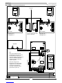
BUS
Art.2321
4
3
N.B.
Dopo ogni cambiamento nella
programmazione del posto esterno,
del videocitofono o del relè, è
necessario togliere l'alimentazione al
sistema e ripristinarla affinchè le
variazioni vengano recepite dai
rispettivi dispositivi.
After each change on the
programming of the door station,
videophone or any other device
connected to the system it is
necessary to restart the system
(power off then power on).
5
Videophone:
Extension N.
1
1
ART.6286
Videophone:
Extension N.
2
1
ART.6286/MV
To next Art.318,
317 or 317N
BUS
OUT
BUS
IN
CLOSE
BUS LINE
Art.318
2
1
46
5
321
ON
Art.4333-0
A
1C
Art.4845
1,5KOhm 1W
12Vac
SE
Art.125
Local Bell Local Bell
Art.: "AMR2-12" power supply.
Use it for memory video model.
MAX N°10 MONITOR
12Vdc
Art.AMR2-12


66251130-EN - V1.4 - 30/06/16
8
6200 Series
Art.6286 - Installation instructions
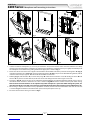
6200 Series Videophone wall mounting instructions
1. In order to install the videophone, it is necessary to remove the cover, which contains all the electronics, from the base: rstly
disconnect the handset from the videophone (by removing its plug from the videophone), then press lightly the bottom part of
the videophone and simultaneously pulling outwards the upper part as shown in Fig. 1.
2. Put the base of the unit on the wall at approx 135cm from the nished oor to mark the points for the xing holes “A” (Fig. 2)
remembering that the wires “D” (Fig. 3) must be fed through the hole “E” (Fig. 3). If you use the ush mounting box 503, embed
it into the wall vertically at approx. 140cm from the nished oor and the base.
3. Following Fig. 3, make the holes “A”, insert the wall plugs “B” and x the base with the screws “C” feeding the wires “D” into
the hole “E”. If you have used the box 503, x the base to the wall through the holes “F” using the screws “C”.
4. As shown in Fig. 4A, connect the wires to the removable terminals following the provided installation diagram. Connect the ter-
minal blocks to the electronics contained in the cover as shown in Fig. 4B. Reinsert the handset and test system before closing.
Note: Contrast and hue trimmers can be adjusted only if the videophone is open. Note while testing the system, it is
advisable to hold the cover with your hand closing manually the hook switch of the handset (see Fig. 4B reference “G”).
5. Once testing is complete and all the necessary adjustments are made, disconnect the handset from the cover and close the unit
as shown in Fig. 5: rst hook it on the bottom then push in the top until you hear the clip.
6. Reconnect the handset and hang it as shown in Fig. 6.
1
2
Fig. 1
A
B
G
Fig. 4
135cm
Fig. 2
1
2
Fig. 5
A
B
A
B
D
F
E
F
C
C
Fig. 3
Fig. 6
-
 1
1
-
 2
2
-
 3
3
-
 4
4
-
 5
5
-
 6
6
-
 7
7
-
 8
8


Videx 6286 Manuale utente
- Categoria
- Impianti citofonici
- Tipo
- Manuale utente
in altre lingue
- English: Videx 6286 User manual
Documenti correlati
-
Videx Security ESVK (4000 Series) Manuale del proprietario
-
Videx 6700 Series Manuale utente
-
-
-
-
-
Videx 2313 Manuale utente