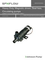
SPX FLOW Heavy Duty Electro-Magnetic Clutch Pump FB-5000 Series Manuale utente
- Tipo
- Manuale utente

INSTRUCTION MANUAL
ORIGINAL INSTRUCTIONS/TRANSLATION OF ORIGINAL INSTRUCTIONS
READ AND UNDERSTAND THIS MANUAL PRIOR TO OPERATING OR SERVICING THIS
PRODUCT
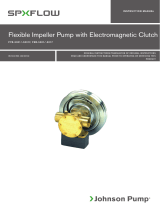
Flexible Impeller Pump with Electromagnetic Clutch
F7B-5000, F8B-5000-VF, F8B-5000-TSS, F9B-5600, F9B-5600-VF, F9B-5600-TSS, F95B-5000
IB-503 R06 (03/2018)

INDEX INDICE
Svenska .......................................................................................................................................3
English .........................................................................................................................................6
Deutsch .......................................................................................................................................9
Français .................................................................................................................................... 12
Español .....................................................................................................................................15
Italiano ......................................................................................................................................18
Made by SPX FLOW Johnson Pump®
SE: Besök www.spxflow.com för mer information om vår världsomspännande organisation, våra godkännanden,
certifieringar och lokala representanter. SPX FLOW, Inc. förbehåller sig rätten att ändra design och material utan
föregående avisering. Designelement, konstruktionsmaterial och dimensioner som beskrivs i denna bulletin gäller
endast som information och skall alltid bekräftas skriftligt för att vara gällande.
EN: For more information about our worldwide locations, approvals, certifications, and local representatives, please visit
www.spxflow.com. SPX FLOW, Inc. reserves the right to incorporate our latest design and material changes without
notice or obligation. Design features, materials of construction and dimensional data, as described in this bulletin,
are provided for your information only and should not be relied upon unless confirmed in writing.
DE: Für weitere Informationen über unsere weltweiten Standorte, Zulassungen, Zertifizierungen und unsere Vertreter
vor Ort, besuchen Sie bitte unsere Webseite: www.spxflow.com. Die SPX FLOW, Inc. behält sich das Recht vor,
die neuesten Konstruktions- und Werkstoffänderungen ohne vorherige Ankündigung und ohne Verpflichtung hierzu
einfließen zu lassen. Konstruktive Ausgestaltungen, Werkstoffe sowie Maßangaben, wie sie in dieser Mitteilung
beschrieben sind, sind nur zur Information. Alle Angaben sind unverbindlich, es sei denn, sie wurden schriftlich
bestätigt.
FR: Pour plus d’information sur nos succursales internationales, nos approbations, nos certifications et nos
représentants locaux, veuillez consulter notre site Internet au www.spxflow.com. SPX FLOW, Inc. se réserve le droit
d’incorporer nos plus récents concepts ainsi que tout autre modification importante sans préavis ou obligation. Les
éléments décoratifs, matériaux de construction et les données dimensionnelles, tels qu’énoncés dans ce communiqué,
sont fournis pour votre information seulement et ne doivent pas être considérés comme officiels à moins d’avis
contraire par écrit.
ES: Para más información sobre nuestras oficinas a nivel mundial, aprobaciones, certificaciones y representantes
locales, por favor visite www.spxflow.com. SPX FLOW, Inc. se reserva el derecho de incorporar nuestro diseño más
reciente y cambios materiales sin necesidad de notificación previa u obligación de ningún tipo. Características de
diseño, materiales de construcción y dimensiones, tal y como están descritas en este boletín, son proporcionadas sólo
con fines informativos y no deben ser usados como referencia a menos que sean confirmados por escrito.
IT: Per ottenere maggiori informazioni sulle nostre sedi nel mondo, autorizzazioni, certificazioni, e rappresentanti locali,
potete visitare il sito www.spxflow.com. La SPX FLOW, Inc. si riserva il diritto di apportare cambiamenti ai propri design
e materiali senza preavviso o vincolo. Le caratteristiche del design, i materiali di costruzione e i dati dimensionali, così
come descritti nel presente bollettino, sono forniti solo per vostra informazione e non saranno oggetto di obbligazione
salvo autorizzazione confermata per iscritto.

3
Översättning av originalinstruktionerna
> Svenska
Typiska användningsområden
• Marint
Länspump, spolpump för däck och
utrustning, kylpump för motorer,
brandpump, sköljning av fisk.
• Industri och jordbruk
Pumpen kan monteras på kraftuttag
på traktorer, vägmaskiner och lik-
nande för bevattning, spolning etc.
Teknisk beskrivning
Pumphus: Brons
Impeller: Neopren alt nitril
(F9B/F95B endast neopren)
Axel: Syrafast stål
Axeln är lagrad i perma-
nentsmorda dubbla kullager
Tätning: Mekanisk tätning
Kam: Hel alt reducerad
Anslutning: Se "Modellspecifikation",
sid 4
Koppling: Elektromagnetisk,
2xA-spår alt 1xB-spår,
Spänning:
12 V DC (4 A)
24 V DC (2 A)
Tryck- och kapacitetsdata
Se sid 26-28.
Serviceinstruktion
Se reservdelslista sid 4-5, 21-25.
Demontering
1. Lossa pumplocket och tag bort pack-
ningen.
2. Tag ur impellern med t ex två skruv-
mejslar.
3. Demontera kammen och tag bort tät-
ningsmedlet på kammen och i pump-
huset.
4. Tag bort slitbrickan.
Självsugande flexibel impellerpump i brons med
elektromagnetisk koppling
5. Avlägsna låsringen (pos 16) och bricka
(F7B/F95B - pos 29) som håller meka-
niska tätningen. F8B/F9B har ingen
bricka.
6. Smörj in axeln framför den mekaniska
tätningen och tryck ner tätningen så
att den släpper greppet om axeln.
7. Skruva ur skruvarna som håller pump-
huset i lagerfoten på F8B/F9B/F95B
(pos 25). Lossa muttern (pos 33)
på F7B. Demontera pumphuset.
8. Tag ur keramikringen från pumphuset.
9. Rengör axel, pumphus, kam och lock.
Avlägsna rester av tätningsmedel.
Montering
1. Fukta keramikringen med såpvatten
(max 5% såpa) och montera den i
pumphuset. Fett och skador får inte
förekomma på tätningsytorna - det
försämrar tätningsförmågan.
2. Skruva fast pumphuset på lagerfoten.
På F7B med mutter (pos 33) och på
F8/F9B/F95B med skruv (pos 25).
3. Fukta glidringen med såpvatten och
pressa den i läge på axeln.
4. Montera på F7B/F95B bricka (pos 29)
och låsring (pos 16) på axeln.
F8B/F9B har ingen bricka.
5. Montera slitbrickan i pumphuset.
6. Applicera tätningsmedel på kam och
kamskruvar. Skruva fast kammen.
7. Smörj impellern med JP Impeller Lubri-
cant och montera med roterande rörelse
i impellerns rotationsriktning.
8. Smörj pumphusets packningsyta med
vaselin eller dylikt. Placera packningen i
läge och skruva fast locket.
Avfallshantering/materialåtervinning
Vid avfallshantering ska produkten lämnas
för destruktion/återvinning enligt gällande
lagstiftning. Vid tillämpliga fall demonteras
och sorteras produkten i ingående material-
fraktioner.

4Översättning av originalinstruktionerna
> Svenska
Pump med neoprenimpeller och helkam
Pumptyp Art nr Anslutning
F7B-5000 10-24116-99 BSP 1"
F7B-5007 10-24116-98 NPTF 1"-111/2
F8B-5000-VF 10-13025-99 Fläns*
F8B-5000-TSS 10-13176-99 Fläns*
F9B-5600 10-13027-99 BSP 2"
F9B-5607 10-13027-98 NPTF 2"-111/2
F9B-5600-TSS 10-13178-99 Fläns**
F9B-5600-VF 10-13226-99 Fläns**
F95B-5000 10-13143-99 BSP 21/2""
F95B-5007 10-13143-98 NPTF 21/2"-8
Vidstående artikelnummer anger
pump exklusive elektromagnetisk
koppling.
Övriga varianter på förfrågan.
* Motfläns för F8B med gänga
BSP 11/2" alt NPTF 111/2"-
111/2, se reservdelslista
** Motfläns för F9B med gänga
BSP 2" alt NPTF 2"-111/2, se
reservdelslista
Modellspecifikation
Elektromagnetisk koppling
Spänning Art nr Spår
12 V 05-32-1 2xA
24 V 05-32-2 2xA
12 V 05-32-3 1xB
24 V 05-32-4 1xB
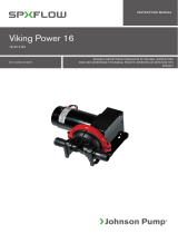
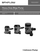
Reservdelslista
F8B-5000-TSS F9B-5600-TSS/VF
Pos Antal Benämning F7B-5000/-5007 F8B-5000/-VF F9B-5600/-5607 F95B-5000/-5007
1 1 Pumphus 01-21862-3
1) 01-11206 01-11358-1 3) 01-13119-2
1 Pumphus 01-21862-5
2) - 01-11358-2
4) -
1 Pumphus-TSS - 01-13002-1 01-13003 -
1 Pumphus-VF - - 01-13224-15) -
2 1 Lock 01-42441 01-42422-1 01-42422-1 01-35284-2
3 1 Axel 01-35084 01-35138 01-35138 01-35700
4 1 Kam 1/1 01-42679 01-42680 01-43137 01-35744
1 Kam 2/3 01-42442 01-42425 01-43135 01-35854
1 Kam 1/2 - 01-42755 01-43138 01-35853
5 1 Impeller 09-1028BT-1 (EPDM) 09-819B (neopren) - 09-820B (neopren)
1 Impeller 09-1028B-9 (nitril) 09-819B-9 (nitril) - -
1 Impeller - - 09-814B (neopren) -
6 1 Packning 01-42445 01-42424 01-42424
6) -
1 O-ring - - 0.2172.142
7) 0.2172.142
7 1 Stift 01-42400 01-42426 01-42426 01-42426
8 1 Slitbricka 01-42443 01-42423 01-42423 01-42423

5
Översättning av originalinstruktionerna
> Svenska
*) pos 5, 6, 13, 28 **) pos 18,19, 20, 21, 24, 35/32
1) BSP 1" – pump 10-24116-99 2) NPTF 1"-111/2 – pump 10-24116-98 3) BSP 2" – pump 10-13027-99
4) NPTF 2"-111/2 – pump 10-13027-98 5) Fläns – pump 10-13226-99 6) Pump 10-13027/13178-99
7) Pump 10-13226-99 8) BSP 21/2" – pump 10-13143-99 9) NPTF 21/2"-8 – pump 10-13143-98
F8B-5000-TSS F9B-5600-TSS/VF
Pos Antal Benämning F7B-5000/-5007 F8B-5000/-5007 F9B-5600/-5607 F95B-5000/-5007
9 1 Lagerfot 01-24098 01-13020 01-13020 01-13131-1
10 1 Distanshylsa 01-45170 01-42747 01-42747 -
11 1 Fästring - 01-35144-2 01-35144-2 -
12 1 V-ring 0.2230.015 0.2230.319 0.2230.319 0.2230.322
13 1 Mek tätning 09-20-115 09-20-118 09-20-118 09-20-534
14 2 Kullager 0.3431.778 0.3431.780 0.3431.780 se pos 39, 40
15 1 Låsring 0.0371.047 0.0371.062 0.0371.062 0.0371.080
16 Låsring 0.0370.516 (1 st) 0.0370.525 (2 st) 0.0370.525 (2 st) 0.0370.535 (1 st)
17 1 Koppling
12 V, 2xA-spår 0.3454.001 0.3454.001 0.3454.001 0.3454.001
24 V, 2xA-spår 0.3454.002 0.3454.002 0.3454.002 0.3454.002
12 V, 1xB-spår 0.3454.003 0.3454.003 0.3454.003 0.3454.003
24 V, 1xB-spår 0.3454.004 0.3454.004 0.3454.004 0.3454.004
18 1 Kil 0.0502.001 0.0502.001 0.0502.001 0.0502.001
19 Bricka 0.0353.309 (1 st) 0.0353.309 (5 st) 0.0353.309 (5 st) 0.0353.309 (1 st)
20 1 Bricka 01-46789-06 01-46789-06 01-46789-06 01-46789-06
21 1 Skruv 0.0141.918 0.0141.918 0.0141.918 0.0141.918
22 3 Skruv - 0.0300.565 0.0300.565 -
23 3 Bricka - 0.0353.402 0.0353.402 0.0353.402
24 3 Skruv 0.0141.903 0.0141.903 0.0141.903 0.0141.903
25 4 Skruv - 0.0144.002 0.0144.002 0.0141.922
26 2 Plugg 0.2500.805 0.2500.805 0.2500.805 -
27 1 Kamskruv 1/1 01-46794-01 01-46794-02 01-46794-02 01-46794-09 (2 st)
1 Kamskruv 2/3 01-46794-07 01-46794-02 01-46794-02 01-46794-11
1 Kamskruv 1/2 - 01-46794-08 01-46794-08 01-46794-11
28 Skruv 01-46794-05 (6 st) 0.0144.200 (5 st) 0.0144.200 (5 st) 0.0138.134 (5 st)
29 1 Bricka 01-45174 - - 01-46323
31 1 Skruv 0.0144.001 - - -
32 1 Bricka 0.0353.402 - - 0.0353.111
33 1 Mutter 0.0194.001 - - -
34 1 Låsring 0.0370.017 - - -
35 1 Bricka 01-45191 - - 01-46322
36 2 Anslutning - - - 01-24426-1 8)
2 Anslutning - - - 01-24426-2 9)
37 2 Packning - - - 01-46319
38 1 Skruv - - - 0.0141.917
39 1 Kullager - - - 0.3431.743
40 1 Kullager - - - 0.3431.043
41 1 Motflänsset - 09-43112 (BSP) 09-46557-01 (BSP) -
1 Motflänsset - 09-45562 (NPTF) 09-46557-02 (NPTF) -
* 1 Servicekit 09-47425 (EPDM) 09-45579 (neopren) - 09-46371 (neopren)
Servicekit 09-45591 (nitril) 09-45580 (nitril) 09-45582 (neopren)
** 1 Monteringssats 09-46436 09-46437 09-46437 09-46437
för koppling

6Original instructions
> English
Typical applications
• Marine
Bilge pump, wash-down for decks and
equipment, emergency engine cooling
pump, emergency fire pump, fish wash-
ing.
• Industry and agriculture
The pump can be mounted on the po-
wer take-off of a tractor, road grader etc
for irrigation, washing etc.
Design features
Body: Bronze
Impeller: Neoprene or nitrile
(F9B/F95B only
neoprene)
Shaft: Stainless steel.
The shaft is mounted
with permanently
lubricated double ball
bearings
Seal: Mechanical
Cam: Full or reduced
Connection: See "Type designation",
page 7
Clutch: Electro-magnetic,
2xA-groove or 1xB-
groove
Supply voltage:
12 V (4 amps) DC
24 V (2 amps) DC
Pressure and capacity data
See page 26-28.
Service instructions
See parts list pages 7-8, 21-25.
Disassembly
1. Remove endcover and gasket.
2. Pull out the impeller using two screw
drivers or other suitable implements.
Self-priming, flexible impeller pump of bronze with
electro-magnetic clutch
3. Remove the cam and wash away resi-
dual traces of sealing compound on the
cam and inside the pump body.
4. Remove the wear plate.
5. Remove the retaining ring (pos 16) and
washer (F7B/F95B - pos 29) holding
the mechanical seal. F8B/F9B has no
washer.
6. Lubricate the shaft in front of the me-
chanical seal and press down the seal
for easier removal from the shaft.
7. Remove the screws holding the pump
body to the pedestal on F8B/F9B/
F95B (pos 25). Loosen the nut (pos 33)
on F7B. Disassemble the pump body.
8. Remove the ceramic ring.
9. Clean shaft, pump body, cam and end-
cover. Wash away any traces of sealing
compound.
Assembly
1. Moisten the ceramic ring with soapy
water (5% soft soap) and mount it in the
pump body. Protect the sealing surfaces
of the mechanical seal against grease
and damages, as it will affect the seal
function.
2. Fasten the pump body onto the pede-
stal. On F7B with nut (pos 33) and on
F8B/F9B/F95B with screw (pos 25).
3. Moisten the rotating ring with soapy
water and press it in its position on the
shaft.
4. Fit the washer (F7B/F95B - pos 29)
and the retaining ring (pos 16) on the
shaft. F8B/F9B has no washer.
5. Mount the wear plate in the pump body.
6. Apply sealing compound to the cam and
cam screws. Fasten the cam.
7. Lubricate the impeller with JP Impel-
ler Lubricant and fit it wit a rotating
movement in the intended direction of
rotation.
8. Lubricate, with vaseline or the like, the
surfaces of the pump body where the
gasket is to be placed. Fit the gasket
and mount the endcover.

7
Original instructions
> English
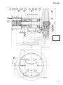
Pos Nos Description F7B-5000/-5007 F8B-5000-VF F9B-5600/-5607 F95B-5000/-5007
1 1 Body 01-21862-3
1) 01-11206 01-11358-1 3) 01-13119-2
1 Body 01-21862-5
2) - 01-11358-2
4) -
1 Body-TSS - 01-13002-1 01-13003 -
1 Body-VF - - 01-13224-1
5) -
2 1 Endcover 01-42441 01-42422-1 01-42422-1 01-35284-2
3 1 Shaft 01-35084 01-35138 01-35138 01-35700
4 1 Cam 1/1 01-42679 01-42680 01-43137 01-35744
1 Cam 2/3 01-42442 01-42425 01-43135 01-35854
1 Cam 1/2 - 01-42755 01-43138 01-35853
5 1 Impeller 09-1028BT-1 (EPDM) 09-819B (neoprene) - 09-820B (neoprene)
1 Impeller 09-1028B-9 (nitrile) 09-819B-9 (nitrile) - -
1 Impeller - - 09-814B (neoprene) -
6 1 Gasket 01-42445 01-42424 01-42424
6) -
1 O-ring - - 0.2172.142
7) 0.2172.142
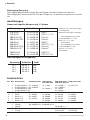
Pump with impeller neoprene and full cam
Pump type Part No Thread
F7B-5000 10-24116-99 BSP 1"
F7B-5007 10-24116-98 NPTF 1"-111/2
F8B-5000-VF 10-13025-99 Flange*
F8B-5000-TSS 10-13176-99 Flange*
F9B-5600 10-13027-99 BSP 2"
F9B-5607 10-13027-98 NPTF 2"-111/2
F9B-5600-TSS 10-13178-99 Flange**
F9B-5600-VF 10-13226-99 Flange**
F95B-5000 10-13143-99 BSP 21/2"
F95B-5007 10-13143-98 NPTF 21/2"-8
Part Nos exclude electromagnetic
clutch.
Other variants on request.
* Port adaptor kit for F8B with
thread BSP 11/2" or NPTF
11/2"-111/2, see spare parts list
** Port adaptor kit for F9B with
thread BSP 2" or NPTF 2"-
111/2, see spare parts list
Type designation
Electro-magnetic clutch
Voltage Part No Pulley
12 V 05-32-1 2xA
24 V 05-32-2 2xA
12 V 05-32-3 1xB
24 V 05-32-4 1xB
Parts list
F8B-5000-TSS F9B-5600-TSS/VF
Waste handling/material recycling
At the products end of life, please dispose of the product according to applicable law.
Where applicable, please disassemble the product and recycle the parts material.

8Original instructions
> English
Pos Nos Description F7B-5000/-5007 F8B-5000/-5007 F9B-5600/-5607 F95B-5000/-5007
7 1 Pin 01-42400 01-42426 01-42426 01-42426
8 1 Wear plate 01-42443 01-42423 01-42423 01-42423
9 1 Pedestal 01-24098 01-13020 01-13020 01-13131-1
10 1 Spacer 01-45170 01-42747 01-42747 -
11 1 Adaptor ring - 01-35144-2 01-35144-2 -
12 1 V-ring 0.2230.015 0.2230.319 0.2230.319 0.2230.322
13 1 Mech. seal 09-20-115 09-20-118 09-20-118 09-20-534
14 2 Ball bearing 0.3431.778 0.3431.780 0.3431.780 see pos 39, 40
15 1 Retaining ring 0.0371.047 0.0371.062 0.0371.062 0.0371.080
16 Retaining ring 0.0370.516 (1 pc) 0.0370.525 (2 pcs) 0.0370.525 (2 pcs) 0.0370.535 (1 pc)
17 1 Clutch
12 V, 2xA-groove 0.3454.001 0.3454.001 0.3454.001 0.3454.001
24 V, 2xA-groove 0.3454.002 0.3454.002 0.3454.002 0.3454.002
12 V, 1xB-groove 0.3454.003 0.3454.003 0.3454.003 0.3454.003
24 V, 1xB-groove 0.3454.004 0.3454.004 0.3454.004 0.3454.004
18 1 Key 0.0502.001 0.0502.001 0.0502.001 0.0502.001
19 Washer 0.0353.309 (1 pc) 0.0353.309 (5 pcs) 0.0353.309 (5 pcs) 0.0353.309 (1 pc)
20 1 Washer 01-46789-06 01-46789-06 01-46789-06 01-46789-06
21 1 Screw 0.0141.918 0.0141.918 0.0141.918 0.0141.918
22 3 Screw - 0.0300.565 0.0300.565 -
23 3 Washer - 0.0353.402 0.0353.402 0.0353.402
24 3 Screw 0.0141.903 0.0141.903 0.0141.903 0.0141.903
25 4 Screw - 0.0144.002 0.0144.002 0.0141.922
26 2 Plug 0.2500.805 0.2500.805 0.2500.805 -
27 1 Camscrew 1/1 01-46794-01 01-46794-02 01-46794-02 01-46794-09 (2 pcs)
1 Camscrew 2/3 01-46794-07 01-46794-02 01-46794-02 01-46794-11
1 Camscrew 1/2 - 01-46794-08 01-46794-08 01-46794-11
28 Screw 01-46794-05 (6 pcs) 0.0144.200 (5 pcs) 0.0144.200(5 pcs) 0.0138.134 (5 pcs)
29 1 Washer 01-45174 - - 01-46323
31 1 Screw 0.0144.001 - - -
32 1 Washer 0.0353.402 - - 0.0353.111
33 1 Nut 0.0194.001 - - -
34 1 Retaining ring 0.0370.017 - - -
35 1 Washer 01-45191 - - 01-46322
36 2 Thread - - - 01-24426-1 8)
2 Thread - - - 01-24426-2 9)
37 2 Gasket - - - 01-46319
38 1 Screw - - - 0.0141.917
39 1 Ball bearing - - - 0.3431.743
40 1 Ball bearing - - - 0.3431.043
41 1 Port adaptor - 09-43112 (BSP) 09-46557-01 (BSP) -
1 Port adaptor - 09-45562 (NPTF) 09-46557-02 (NPTF) -
* 1 Service kit 09-47425 (EPDM) 09-45579 (neoprene) - 09-46371 (neoprene)
Service kit 09-45591 (nitrile) 09-45580 (nitrile) 09-45582 (neoprene)
** 1 Assembly kit 09-46436 09-46437 09-46437 09-46437
for clutch
*) pos 5, 6, 13, 28 **) pos 18, 19, 20, 21, 24, 35/32
1) BSP 1" – pump 10-24116-99 2) NPTF 1"-111/2 – pump 10-24116-98 3) BSP 2" – pump 10-13027-99
4) NPTF 2"-111/2 – pump 10-13027-98 5) Flange – pump 10-13226-99 6) Pump 10-13027/13178-99
7) Pump 10-13226-99 8) BSP 21/2" – pump 10-13143-99 9) NPTF 21/2"-8 – pump 10-13143-98
F8B-5000-TSS F9B-5600-TSS/VF

9
Übersetzung der Original-Betriebanleitungen
> Deutsch
Pos Nos Description F7B-5000/-5007 F8B-5000/-5007 F9B-5600/-5607 F95B-5000/-5007
7 1 Pin 01-42400 01-42426 01-42426 01-42426
8 1 Wear plate 01-42443 01-42423 01-42423 01-42423
9 1 Pedestal 01-24098 01-13020 01-13020 01-13131-1
10 1 Spacer 01-45170 01-42747 01-42747 -
11 1 Adaptor ring - 01-35144-2 01-35144-2 -
12 1 V-ring 0.2230.015 0.2230.319 0.2230.319 0.2230.322
13 1 Mech. seal 09-20-115 09-20-118 09-20-118 09-20-534
14 2 Ball bearing 0.3431.778 0.3431.780 0.3431.780 see pos 39, 40
15 1 Retaining ring 0.0371.047 0.0371.062 0.0371.062 0.0371.080
16 Retaining ring 0.0370.516 (1 pc) 0.0370.525 (2 pcs) 0.0370.525 (2 pcs) 0.0370.535 (1 pc)
17 1 Clutch
12 V, 2xA-groove 0.3454.001 0.3454.001 0.3454.001 0.3454.001
24 V, 2xA-groove 0.3454.002 0.3454.002 0.3454.002 0.3454.002
12 V, 1xB-groove 0.3454.003 0.3454.003 0.3454.003 0.3454.003
24 V, 1xB-groove 0.3454.004 0.3454.004 0.3454.004 0.3454.004
18 1 Key 0.0502.001 0.0502.001 0.0502.001 0.0502.001
19 Washer 0.0353.309 (1 pc) 0.0353.309 (5 pcs) 0.0353.309 (5 pcs) 0.0353.309 (1 pc)
20 1 Washer 01-46789-06 01-46789-06 01-46789-06 01-46789-06
21 1 Screw 0.0141.918 0.0141.918 0.0141.918 0.0141.918
22 3 Screw - 0.0300.565 0.0300.565 -
23 3 Washer - 0.0353.402 0.0353.402 0.0353.402
24 3 Screw 0.0141.903 0.0141.903 0.0141.903 0.0141.903
25 4 Screw - 0.0144.002 0.0144.002 0.0141.922
26 2 Plug 0.2500.805 0.2500.805 0.2500.805 -
27 1 Camscrew 1/1 01-46794-01 01-46794-02 01-46794-02 01-46794-09 (2 pcs)
1 Camscrew 2/3 01-46794-07 01-46794-02 01-46794-02 01-46794-11
1 Camscrew 1/2 - 01-46794-08 01-46794-08 01-46794-11
28 Screw 01-46794-05 (6 pcs) 0.0144.200 (5 pcs) 0.0144.200(5 pcs) 0.0138.134 (5 pcs)
29 1 Washer 01-45174 - - 01-46323
31 1 Screw 0.0144.001 - - -
32 1 Washer 0.0353.402 - - 0.0353.111
33 1 Nut 0.0194.001 - - -
34 1 Retaining ring 0.0370.017 - - -
35 1 Washer 01-45191 - - 01-46322
36 2 Thread - - - 01-24426-1 8)
2 Thread - - - 01-24426-2 9)
37 2 Gasket - - - 01-46319
38 1 Screw - - - 0.0141.917
39 1 Ball bearing - - - 0.3431.743
40 1 Ball bearing - - - 0.3431.043
41 1 Port adaptor - 09-43112 (BSP) 09-46557-01 (BSP) -
1 Port adaptor - 09-45562 (NPTF) 09-46557-02 (NPTF) -
* 1 Service kit 09-47425 (EPDM) 09-45579 (neoprene) - 09-46371 (neoprene)
Service kit 09-45591 (nitrile) 09-45580 (nitrile) 09-45582 (neoprene)
** 1 Assembly kit 09-46436 09-46437 09-46437 09-46437
for clutch
Anwendungsbeispiele
• Marinebereich
Lenzpumpe, Deckwaschpumpe, Kühl-
wasserpumpe für Motoren, Feuerlösch-
pumpe, zum Abspülen von Ausrüstungen
und eingebrachter Fänge auf Fischerei-
fahrzeugen.
• Industrie und Landwirtschaft
Die Pumpe kann an die Kraftabnahmen
der Motoren von LKW's, Traktoren,
Strassenbaumaschinen etc. zum Bewäs-
sern, Spülen angebracht werden.
Technische Beschreibung
Pumpen-
gehäuse: Bronze
Impeller: Neoprene oder Nitrile
(F9B/F95B -Neoprene)
Welle: Edelstahl mit zwei
dauergeschmierten
Kugellagern
Dichtung: Gleitringdichtung
Kamm: 1/1 oder reduzierter Kamm
Anschlüsse: Siehe "Ausführung",
Seite 10
Kupplung: Elektromagnetisch,
2xA-Profil oder, 1xB-
Profil
Spannung: 12 V (4 A)
24 V (2 A)
Druck und Leistungsdaten
Siehe Seite 26-28.
Bedienungsanleitungen
Siehe Ersatzteilliste Seite 10-11, 21-25.
Demontage
1. Deckelschrauben lösen, Deckel und
Dichtung entfernen.
2. Der Impeller mit Hilfe von zwei Schrau-
benziehern oder dem Impellerabzieher
herausziehen.
3. Nach Ausbau des Kamms Dichtungs-
reste vom Pumpengehäuse und Kamm
entfernen.
Selbstansaugende flexible Impellerpumpe aus
Bronze auf Sockel montiert
4. Verschleisplatte entfernen.
5. Sicherungsring (Pos 16) und Scheibe
(F7B/F95B) der mechanischen Dich-
tung entfernen.
F8B/F9B ist keine Scheibe montiert.
6. Welle vor der mechanischen Dichtung
einfetten und Dichtung über die Welle
einpressen.
7. Schrauben die das Pumpengehäuse auf
dem Sockel halten entfernen. Gilt für die
Pumpen F8B/F9B/F95B (Pos 25).
Bei F7B Muttern (Pos 33) abschrauben.
Demontage des Pumpengehäuse.
8. Keramikring aus dem Pumpengehäuse
herausnehmen.
9. Welle, Pumpengehäuse, Kamm und
Deckel von Dichtungsresten reinigen.
Montage
1. Keramikring mit Seifenlauge anfeuchten
(max 5% Mischung) und in das Pum-
pengehäuse einfügen. Fett und Beschä-
digung vermeiden, Dichtungseffekt wird
sonst verschlechtert.
2. Pumpengehäuse F8B/F9B/F95B mit
den Schrauben auf dem Sockel fest-
schrauben (Pos 25). F7B wird mit Mut-
tern (Pos 33) befestigt.
3. Gleitring mit Seifenlauge anfeuchten und
über die Welle pressen.
4. Bei F7B/F95B Scheibe (Pos 29)
montieren und mit dem Sicherungsring
(Pos 16) an der Welle sichern. F8B/F9B
ohne Scheibe.
5. Verschleisplatte im Pumpengehäuse
montieren.
6. Dichtungsmittel auf den Kamm und
die Kammschrauben auftragen und die
Schrauben fest anziehen.
7. Impeller einfetten (mit JP Impeller Lubri-
cant) und in Drehrichtung des Impellers
montieren.
8. Auf die Dichtungsfläche des Pumpen-
gehäuse Vaseline oder desgleichen
auftragen, Packung auflegen und den
Deckel festschrauben.
*) pos 5, 6, 13, 28 **) pos 18, 19, 20, 21, 24, 35/32
1) BSP 1" – pump 10-24116-99 2) NPTF 1"-111/2 – pump 10-24116-98 3) BSP 2" – pump 10-13027-99
4) NPTF 2"-111/2 – pump 10-13027-98 5) Flange – pump 10-13226-99 6) Pump 10-13027/13178-99
7) Pump 10-13226-99 8) BSP 21/2" – pump 10-13143-99 9) NPTF 21/2"-8 – pump 10-13143-98

10 Übersetzung der Original-Betriebanleitungen
> Deutsch
Pos Nos Bezeichnung F7B-5000/-5007 F8B-5000-VF F9B-5600/-5607 F95B-5000/-5007
1 1 Pumpengehäuse 01-21862-3 1) 01-11206 01-11358-1 3) 01-13119-2
1 Pumpengehäuse 01-21862-5 2) - 01-11358-2 4) -
1 Pumpengehäuse-TSS 01-13002-1 01-13003 -
1 Pumpengehäuse-VF - 01-13224-1
5) -
2 1 Deckel 01-42441 01-42422-1 01-42422-1 01-35284
3 1 Welle 01-35084 01-35138 01-35138 01-35700
4 1 Kamm 1/1 01-42679 01-42680 01-43137 01-35744
4 1 Kamm 2/3 01-42442 01-42425 01-43135 01-35854
4 1 Kamm 1/2 - 01-42755 01-43138 01-35853
5 1 Impeller 09-1028BT-1 (EPDM) 09-819B (Neopren) - 09-820B (Neopren)
1 Impeller 09-1028B-9 (Nitril) 09-819B-9 (Nitril) - -
1 Impeller - - 09-814B (Neopren) -
6 1 Dichtung 01-42445 01-42424 01-42424
6) -
1 O-ring - - 0.2172.142
7) 0.2172.142
Artikel-Nr. links, ohne elektromagne-
tische Kupplung.
Weitere Ausführungen auf Anfrage.
* Anschlußadaptersatz für F8B
mit gewinde BSP 11/2" oder
NPTF 11/2"-111/2, siehe
Erstatzteilliste
** Anschlußadaptersatz für F9B
mit gewinde BSP 2" oder
NPTF 2"-111/2, siehe
Erstatzteilliste
Pumpe mit Impeller Neopren und 1/1 Kamm
Pumpentyp Artikel-Nr. Anschluss
F7B-5000 10-24116-99 BSP 1"
F7B-5007 10-24116-98 NPTF 1"-111/2
F8B-5000-VF 10-13025-99 Flansch*
F8B-5000-TSS 10-13176-99 Flansch*
F9B-5600 10-13027-99 BSP 2"
F9B-5607 10-13027-98 NPTF 2"-111/2
F9B-5600-TSS 10-13178-99 Flansch**
F9B-5600-VF 10-13226-99 Flansch**
F95B-5000 10-13143-99 BSP 21/2"
F95B-5007 10-13143-98 NPTF 21/2"-8
Ausführungen
Elektromagnetische Kupplung
Spannung Artikel-Nr. Profil
12 V 05-32-1 2xA
24 V 05-32-2 2xA
12 V 05-32-3 1xB
24 V 05-32-4 1xB
Ersatzteilliste
F8B-5000-TSS F9B-5600-TSS/VF
Entsorgung/Recycling
Nach Lebensdauerende entsorgen Sie die Pumpe nach den örtlichen Vorschriften.
Nach Möglichkeit demontieren Sie Teile der Pumpe um sie dem Recycling-Process zuzufüh-
ren.

11
Übersetzung der Original-Betriebanleitungen
> Deutsch
Pos Nos Bezeichnung F7B-5000/-5007 F8B-5000-VF F9B-5600/-5607 F95B-5000/-5007
1 1 Pumpengehäuse 01-21862-3 1) 01-11206 01-11358-1 3) 01-13119-2
1 Pumpengehäuse 01-21862-5 2) - 01-11358-2 4) -
1 Pumpengehäuse-TSS 01-13002-1 01-13003 -
1 Pumpengehäuse-VF - 01-13224-1
5) -
2 1 Deckel 01-42441 01-42422-1 01-42422-1 01-35284
3 1 Welle 01-35084 01-35138 01-35138 01-35700
4 1 Kamm 1/1 01-42679 01-42680 01-43137 01-35744
4 1 Kamm 2/3 01-42442 01-42425 01-43135 01-35854
4 1 Kamm 1/2 - 01-42755 01-43138 01-35853
5 1 Impeller 09-1028BT-1 (EPDM) 09-819B (Neopren) - 09-820B (Neopren)
1 Impeller 09-1028B-9 (Nitril) 09-819B-9 (Nitril) - -
1 Impeller - - 09-814B (Neopren) -
6 1 Dichtung 01-42445 01-42424 01-42424
6) -
1 O-ring - - 0.2172.142
7) 0.2172.142
*) pos 5, 6, 13, 28 **) pos 18, 19, 20, 21, 24, 35/32
1) BSP 1" – Pumpe 10-24116-99 2) NPTF 1"-111/2 – Pumpe 10-24116-98 3) BSP 2" – Pumpe 10-13027-99
4) NPTF 2"-111/2 – Pumpe 10-13027-98 5) Flansch – Pumpe 10-13226-99 6) Pumpe 10-13027/13178-99
7) Pumpe 10-13226-99 8) BSP 21/2" – Pumpe 10-13143-99 9) NPTF 21/2"-8 – Pumpe 10-13143-98
F8B-5000-TSS F9B-5600-TSS/VF
Pos Nos Bezeichnung F7B-5000/-5007 F8B-5000/-5007 F9B-5600/-5607 F95B-5000/-5007
7 1 Stift 01-42400 01-42426 01-42426 01-42426
8 1 Schleissplatte 01-42443 01-42423 01-42423 01-42423
9 1 Lagerfuss 01-24098 01-13020 01-13020 01-13131-1
10 1 Distanzhülze 01-45170 01-42747 01-42747 -
11 1 Befestigungsring - 01-35144-2 01-35144-2 -
12 1 V-ring 0.2230.015 0.2230.319 0.2230.319 0.2230.322
13 1 Gleitringdichtung 09-20-115 09-20-118 09-20-118 09-20-534
14 2 Kugellager 0.3431.778 0.3431.780 0.3431.780 Siehe pos 39, 40
15 1 Sicherungsring 0.0371.047 0.0371.062 0.0371.062 0.0371.080
16 Sicherungsring 0.0370.516 (1 st) 0.0370.525 (2 st) 0.0370.525 (2 st) 0.0370.535 (1 st)
17 1 Kupplung
12 V, 2xA-Profil 0.3454.001 0.3454.001 0.3454.001 0.3454.001
24 V, 2xA-Profil 0.3454.002 0.3454.002 0.3454.002 0.3454.002
12 V, 1xB-Profil 0.3454.003 0.3454.003 0.3454.003 0.3454.003
24 V, 1xB-Profil 0.3454.004 0.3454.004 0.3454.004 0.3454.004
18 1 Keil 0.0502.001 0.0502.001 0.0502.001 0.0502.001
19 Scheibe 0.0353.309 (1 st) 0.0353.309 (5 st) 0.0353.309 (5 st) 0.0353.309 (1 st)
20 1 Scheibe 01-46789-06 01-46789-06 01-46789-06 01-46789-06
21 1 Schraube 0.0141.918 0.0141.918 0.0141.918 0.0141.918
22 3 Schraube - 0.0300.565 0.0300.565 -
23 3 Scheibe - 0.0353.402 0.0353.402 0.0353.402
24 3 Schraube 0.0141.903 0.0141.903 0.0141.903 0.0141.903
25 4 Schraube - 0.0144.002 0.0144.002 0.0141.922
26 2 Stopfen 0.2500.805 0.2500.805 0.2500.805 -
27 1 Kammschraube 1/1 01-46794-01 01-46794-02 01-46794-02 01-46794-09 (2 st)
1 Kammschraube 2/3 01-46794-07 01-46794-02 01-46794-02 01-46794-11
1 Kammschraube 1/2 - 01-46794-08 01-46794-08 01-46794-11
28 Schraube 01-46794-05 (6 st) 0.0144.200 (5 st) 0.0144.200 (5 st) 0.0138.134 (5 st)
29 1 Scheibe 01-45174 - - 01-46323
31 1 Schraube 0.0144.001 - - -
32 1 Scheibe 0.0353.402 - - 0.0353.111
33 1 Mutter 0.0194.001 - - -
34 1 Sicherungsring 0.0370.017 - - -
35 1 Scheibe 01-45191 - - 01-46322
36 2 Anschluss - - - 01-24426-1 8)
2 Anschluss - - - 01-24426-2 9)
37 2 Dichtung - - - 01-46319
38 1 Schraube - - - 0.0141.917
39 1 Kugellager - - - 0.3431.743
40 1 Kugellager - - - 0.3431.043
41 1 Anschlußsatz - 09-43112 (BSP) 09-46557-01 (BSP) -
1 Anschlußsatz - 09-45562 (NPTF) 09-46557-02 (NPTF) -
* 1 Servicesatz 09-47425 (EPDM) 09-45579 (Neopren) - 09-46371 (Neopren)
Servicesatz 09-45591 (Nitril) 09-45580 (Nitril) 09-45582 (Neopren)
** 1 Montagesatz 09-46436 09-46437 09-46437 09-46437
für Kupplung

12 Traduction du manuel d'instruction d'origine
> Français
Types d'applications
• Marine
Pompe de cale, pompe de lavage de
pont, pompe de secours pour refroidis-
sement, pompe d'incendie, lavage de
poisson.
• Industrie et agriculture
Pompe pour montage sur prise de force
de tracteur, d'engins travaux publics,
pompe d'irrigation, lavage, etc.
Specification
Corps: Bronze
Rotor: Néoprène ou nitrile
(F9B/F95B - néoprène)
Arbre: Acier inoxydable
L'arbre est monté sur deux
roulements lubrifiés "à vie"
Joint: Mécanique
Came: Pleine ou réduite
Orifices: Voir "Spécifications du
modèle", page 13
Embrayage: Gorge electromagnétique,
2 x rainure A ou 1 x rainure B
Tension courant continu:
12 V (4 A)
24 V (2 A)
Pressions et débits
Voir page 26-28.
Instructions d'entretien
Voir liste des pièces pages 13-14, 21-25.
Démontage
1. Démonter le couvercle et le joint.
2. Retirer le rotor en utilisant 2 tournevis ou
autre objet adéquat.
3. Retirer la came et nettoyer toute trace de
pâte à joint sur la came et à l'intèrieur du
corps de la pompe.
4. Déposer la plaque d'usure.
5. Retirer le clips (rep 16) et la ron-
delle (F7B/F95B - rep 29) retenant
l'étancheité. F8B/F9B n'ont pas de
rondelle.
Pompes auto-amorçantes en bronze à rotor flexible
avec embrayage electromagnétique
6. Lubrifier l'arbre (eau ou huile) afin de
faciliter le glissement de l'étancheité,
la presser puis la sortir.
7. Dévisser le corps de pompe de son pa-
lier support (pour F8B/F9B/F95B - rep
25). Désserer l'ecrou (rep 33) pour F7B.
Démonter le corps.
8. Rétirer la glace en ceramique.
9. Nettoyer toutes ces pièces et retirer
toute trace de pâte à joint.
Montage
1. Mouiller la glace en ceramique avec de
l'eau savonneuse et la mettre en place
dans le corps de pompe. Protegér des
chocs les faces tournantes du joint - ne
pas les graisser.
2. Fixer le corps de pompe sur son palier
support: sur F7B par serrage de l'écrou
(rep 33), sur F8B/F9B/F95B par les vis
(rep 25).
3. Mouiller la partie tournante du joint avec
de l'eau savonneuse et la mettre en place
sur l'arbre.
4. Mettre en place la rondelle sur F7B/
F95B (rep 29) et le circlips (rep 16) sur
l'arbre. F8B/F9B n'ont pas de rondelle.
5. Mettre la plaque d'usure dans le corps de
pompe.
6. Mettre de la pâte à joint sur la came et la
vis de came, puis serrer la vis de came.
7. Lubrifiez le rotor avec le lubrifiant JP
Impeller Lubricant en place en le faisant
tourner dans le sens de rotation de la
pompe.
8. Mettre un peu de vaseline ou similaire
sur le face du couvercle, côté rotor puis
visser le couvercle avec son joint.
Gestion des déchets/recyclage des
matériaux
Lorsque le matériel arrivera en fin de vie,
veuillez le mettre au rebut en fonction des
lois applicables. Lorsque c’est possible,
veuillez démonter le matériel et recycler les
pièces pouvant l’être

13
Traduction du manuel d'instruction d'origine
> Français
Embrayage electromagnétique
Tension Référence Gorge
12 V 05-32-1 2xA
24 V 05-32-2 2xA
12 V 05-32-3 1xB
24 V 05-32-4 1xB
Pompe avec rotor néoprène et came hauteur maxi
Modèle Référence Orifice
F7B-5000 10-24116-99 BSP 1"
F7B-5007 10-24116-98 NPTF 1"-111/2
F8B-5000-VF 10-13025-99 Flange*
F8B-5000-TSS 10-13176-99 Flange*
F9B-5600 10-13027-99 BSP 2"
F9B-5607 10-13027-98 NPTF 2"-111/2
F9B-5600-TSS 10-13178-99 Flange**
F9B-5600-VF 10-13226-99 Flange**
F95B-5000 10-13143-99 BSP 21/2"
F95B-5007 10-13143-98 NPTF 21/2"-8
Spécifications du modèle
Les références ne comprennent pas
l'embrayage electromagnétique.
Options:
* Kit de contrebrides pour F8B
ø 11/2" BSP ou NPTF
** Kit de contrebrides pour F9B
ø 2" BSP ou NPTF
Liste des pièces
Pos Nos Description F7B-5000/-5007 F8B-5000-VF F9B-5600/-5607 F95B-5000/-5007
1 1 Corps 01-21862-3
1) 01-11206 01-11358-1 3) 01-13119-2
1 Corps 01-21862-5
2) - 01-11358-2
4) -
1 Corps-TSS - 01-13002-1 01-13003 -
1 Corps-VF - - 01-13224-1
5) -
2 1 Couvercle 01-42441 01-42422-1 01-42422-1 01-35284-2
3 1 Arbre 01-35084 01-35138 01-35138 01-35700
4 1 Came 1/1 01-42679 01-42680 01-43137 01-35744
1 Came 2/3 01-42442 01-42425 01-43135 01-35854
1 Came 1/2 - 01-42755 01-43138 01-35853
5 1 Rotor 09-1028BT-1 (EPDM) 09-819B (néoprène) - 09-820B (néoprène)
1 Rotor 09-1028B-9 (nitrile) 09-819B-9 (nitrile) - -
1 Rotor - - 09-814B (néoprène) -
6 1 Joint 01-42445 01-42424 01-42424
6) -
1 O-ring - - 0.2172.142
7) 0.2172.142
7 1 Ergot 01-42400 01-42426 01-42426 01-42426
8 1 Plaque d'usure 01-42443 01-42423 01-42423 01-42423
9 1 Palier/Support 01-24098 01-13020 01-13020 01-13131-1
10 1 Entretoise 01-45170 01-42747 01-42747 -
F8B-5000-TSS F9B-5600-TSS/VF

14 Traduction du manuel d'instruction d'origine
> Français
Pos Nos Description F7B-5000/-5007 F8B-5000/-5007 F9B-5600/-5607 F95B-5000/-5007
11 1 Bague adapteur - 01-35144-2 01-35144-2 -
12 1 V-ring 0.2230.015 0.2230.319 0.2230.319 0.2230.322
13 1 Garniture mech. 09-20-115 09-20-118 09-20-118 09-20-534
14 2 Roulements
à billes 0.3431.778 0.3431.780 0.3431.780 voir pos 39, 40
15 1 Clips 0.0371.047 0.0371.062 0.0371.062 0.0371.080
16 Clips 0.0370.516 (1 pc) 0.0370.525 (2 pcs) 0.0370.525 (2 pcs) 0.0370.535 (1 pc)
17 1 Embrayage
12 V, 2 gorges A 0.3454.001 0.3454.001 0.3454.001 0.3454.001
24 V, 2 gorges A 0.3454.002 0.3454.002 0.3454.002 0.3454.002
12 V, 1 gorge B 0.3454.003 0.3454.003 0.3454.003 0.3454.003
24 V, 1 gorge B 0.3454.004 0.3454.004 0.3454.004 0.3454.004
18 1 Clavette 0.0502.001 0.0502.001 0.0502.001 0.0502.001
19 Rondelle 0.0353.309 (1 pc) 0.0353.309 (5 pcs) 0.0353.309 (5 pcs) 0.0353.309 (1 pc)
20 1 Rondelle 01-46789-06 01-46789-06 01-46789-06 01-46789-06
21 1 Vis 0.0141.918 0.0141.918 0.0141.918 0.0141.918
22 3 Vis - 0.0300.565 0.0300.565 -
23 3 Rondelle - 0.0353.402 0.0353.402 0.0353.402
24 3 Vis 0.0141.903 0.0141.903 0.0141.903 0.0141.903
25 4 Vis - 0.0144.002 0.0144.002 0.0141.922
26 2 Bouchon 0.2500.805 0.2500.805 0.2500.805 -
27 1 Vis de came 1/1 01-46794-01 01-46794-02 01-46794-02 01-46794-09(2 pcs)
1 Vis de came 2/3 01-46794-07 01-46794-02 01-46794-02 01-46794-11
1 Vis de came 1/2 - 01-46794-08 01-46794-08 01-46794-11
28 Vis 01-46794-05 (6 pcs) 0.0144.200 (5 pcs) 0.0144.200 (5 pcs) 0.0138.134 (5 pcs)
29 1 Rondelle 01-45174 - - 01-46323
31 1 Vis 0.0144.001 - - -
32 1 Rondelle 0.0353.402 - - 0.0353.111
33 1 Ecrou 0.0194.001 - - -
34 1 Clips 0.0370.017 - - -
35 1 Rondelle 01-45191 - - 01-46322
36 2 Raccord - - - 01-24426-1 8)
2 Raccord - - - 01-24426-2 9)
37 2 Joint - - - 01-46319
38 1 Vis - - - 0.0141.917
39 1 Roulements à billes - - 0.3431.743
40 1 Roulements à billes - - 0.3431.043
41 1 Jeu d'adapteur - 09-43112 (BSP) 09-46557-01 (BSP) -
1 Jeu d'adapteur - 09-45562 (NPTF) 09-46557-02 (NPTF) -
* 1 Kit de réparation 09-47425 (EPDM) 09-45579 (néoprène) - 09-46371 (néoprène)
Kit de réparation 09-45591 (nitrile) 09-45580 (nitrile) 09-45582 (néoprène)
** 1 Kit de montage 09-46436 09-46437 09-46437 09-46437
pour embrayage
F8B-5000-TSS F9B-5600-TSS/VF
*) pos 5, 6, 13, 28 **) pos 18,19, 20, 21, 24, 35/32
1) BSP 1" – pompe 10-24116-99 2) NPTF 1"-111/2 – pompe 10-24116-98
3) BSP 2" – pompe 10-13027-99 4) NPTF 2"-111/2 – pompe 10-13027-98
5) Flange – pompe 10-13226-99 6) Pompe 10-13027/13178-99
7 Pompe 10-13226-99 8) BSP 21/2" – pompe 10-13143-99
9) NPTF 21/2"-8 – pompe 10-13143-98

15
Traducción de instrucciones originales
> Español
Pos Nos Description F7B-5000/-5007 F8B-5000/-5007 F9B-5600/-5607 F95B-5000/-5007
11 1 Bague adapteur - 01-35144-2 01-35144-2 -
12 1 V-ring 0.2230.015 0.2230.319 0.2230.319 0.2230.322
13 1 Garniture mech. 09-20-115 09-20-118 09-20-118 09-20-534
14 2 Roulements
à billes 0.3431.778 0.3431.780 0.3431.780 voir pos 39, 40
15 1 Clips 0.0371.047 0.0371.062 0.0371.062 0.0371.080
16 Clips 0.0370.516 (1 pc) 0.0370.525 (2 pcs) 0.0370.525 (2 pcs) 0.0370.535 (1 pc)
17 1 Embrayage
12 V, 2 gorges A 0.3454.001 0.3454.001 0.3454.001 0.3454.001
24 V, 2 gorges A 0.3454.002 0.3454.002 0.3454.002 0.3454.002
12 V, 1 gorge B 0.3454.003 0.3454.003 0.3454.003 0.3454.003
24 V, 1 gorge B 0.3454.004 0.3454.004 0.3454.004 0.3454.004
18 1 Clavette 0.0502.001 0.0502.001 0.0502.001 0.0502.001
19 Rondelle 0.0353.309 (1 pc) 0.0353.309 (5 pcs) 0.0353.309 (5 pcs) 0.0353.309 (1 pc)
20 1 Rondelle 01-46789-06 01-46789-06 01-46789-06 01-46789-06
21 1 Vis 0.0141.918 0.0141.918 0.0141.918 0.0141.918
22 3 Vis - 0.0300.565 0.0300.565 -
23 3 Rondelle - 0.0353.402 0.0353.402 0.0353.402
24 3 Vis 0.0141.903 0.0141.903 0.0141.903 0.0141.903
25 4 Vis - 0.0144.002 0.0144.002 0.0141.922
26 2 Bouchon 0.2500.805 0.2500.805 0.2500.805 -
27 1 Vis de came 1/1 01-46794-01 01-46794-02 01-46794-02 01-46794-09(2 pcs)
1 Vis de came 2/3 01-46794-07 01-46794-02 01-46794-02 01-46794-11
1 Vis de came 1/2 - 01-46794-08 01-46794-08 01-46794-11
28 Vis 01-46794-05 (6 pcs) 0.0144.200 (5 pcs) 0.0144.200 (5 pcs) 0.0138.134 (5 pcs)
29 1 Rondelle 01-45174 - - 01-46323
31 1 Vis 0.0144.001 - - -
32 1 Rondelle 0.0353.402 - - 0.0353.111
33 1 Ecrou 0.0194.001 - - -
34 1 Clips 0.0370.017 - - -
35 1 Rondelle 01-45191 - - 01-46322
36 2 Raccord - - - 01-24426-1 8)
2 Raccord - - - 01-24426-2 9)
37 2 Joint - - - 01-46319
38 1 Vis - - - 0.0141.917
39 1 Roulements à billes - - 0.3431.743
40 1 Roulements à billes - - 0.3431.043
41 1 Jeu d'adapteur - 09-43112 (BSP) 09-46557-01 (BSP) -
1 Jeu d'adapteur - 09-45562 (NPTF) 09-46557-02 (NPTF) -
* 1 Kit de réparation 09-47425 (EPDM) 09-45579 (néoprène) - 09-46371 (néoprène)
Kit de réparation 09-45591 (nitrile) 09-45580 (nitrile) 09-45582 (néoprène)
** 1 Kit de montage 09-46436 09-46437 09-46437 09-46437
pour embrayage
Aplicaciones usuales
• Maritimo
Bomba de achique, baldeo, bomba
de refrigeración para motores,
bomba contra incendios, lavado de
pescado, etc.
• Industria y agricultura
La bomba puede montarse en la
toma de un tractor y otras máquinas
de obras públicas para fumigar, regar,
lavar, etc.
Características técnicas
Cuerpo: Bronce
Impulsor: Neopreno o nitrilo
(F9B/F95B - neopreno)
Eje: Acero inoxidable con doble
cojinete a bolas de engrase
permanente
Retén: Mecánico
Leva: Completa o reducida
Conexión: Ver "Modelo", página 16
Embrague: Electromagnético, dos
canales 2 x A o un canal 1 x B
Tensión (corriente continua):
12 V (4 A)
24 V (2 A)
Caudales y presiones
Ver página 26-28.
Instrucciones mantenimiento
Ver despiece en página 16-17, 21-25.
Desmontaje
1. Quitar la tapa y la junta.
2. Sacar el impulsor utilizando dos destor-
nilladores.
3. Desmontar la leva y limpiar los residuos
del interior de la bomba y de la leva.
4. Quitar la pletina.
5. Sacar el anillo de fijación (pos 16) y la
arandela (F7B/F95B - pos 29), dejando
el retén macánico. La F8B/F9B no
tienen arandela.
Bombas de bronce autocebantes de impulsor flex-
ible y con embrague electromagnético
6. Engrasar el eje por delante del retén
mecánico y presionar hacia abajo el
retén para facilitar su extracción .
7. En los modelos F8B/F9B/F95B, sacar
los tornillos que fijan la bomba al pede-
stal (pos 25). En el modelo F7B, sacar la
tuerca (pos 33). Desmontar el cuerpo.
8. Quitar el aro cerámico.
9. Limpiar el eje, el interior de la bomba, la
leva y la tapa. Sacar cualquier resto de
grasa o silicona.
Montaje
1. Montar el aro cerámico en el interior
de la bomba utilizando agua jabonosa
(5% jabón suave). Proteger la parte
estanca del retén mecánico de la grasa
o desper-fectos, ya que dañaría su
estanqueidad.
2. Atornillar la bomba al pedestal. En el
modelo F7B con la tuerca (pos 33) y en
F8B/F9B/F95B con los tornillos (pos
25).
3. Con agua jabonosa colocar el aro gira-
torio en el eje.
4. Poner la arandela (F7B/F95B - pos 29)
y el anillo de fijación (pos 16) en el eje.
Los modelos F8B/F9B no llevan aran-
dela.
5. Montar la pletina dentro de la bomba.
6. Aplicar silicona en la leva y su tornillo.
Fijar la leva.
7. Lubrique el impulsor con lubricante
Johnson y colóquelo con un movimiento
giratorio en la dirección de rotación
prevista.
8. Lubricar con vaselina o similar la parte
de la bomba donde deba colocarse la
junta. Poner la junta y atornillar la tapa.
Desguace/Reciclado
Al final de la vida del equipo disponga de
este de acuerdo a la ley. Donde sea de
aplicación desmonte el equipo y recicle los
diferentes materiales.

16 Traducción de instrucciones originales
> Español
Bomba con impulsor de neopreno y leva entera
Tipo Modelo Conexión
F7B-5000 10-24116-99 BSP 1"
F7B-5007 10-24116-98 NPTF 1"-111/2
F8B-5000-VF 10-13025-99 Brida*
F8B-5000-TSS 10-13176-99 Brida*
F9B-5600 10-13027-99 BSP 2"
F9B-5607 10-13027-98 NPTF 2"-111/2
F9B-5600-TSS 10-13178-99 Brida**
F9B-5600-VF 10-13226-99 Brida**
F95B-5000 10-13143-99 BSP 21/2"
F95B-5007 10-13143-98 NPTF 21/2"-8
Modelo
Embrague electromagnético
Tensión Modelo Polea
12 V 05-32-1 2xA
24 V 05-32-2 2xA
12 V 05-32-3 1xB
24 V 05-32-4 1xB
Estos modelos no incluyen el em-
brague electromagnético.
Otras varaintes sobre pedido.
* Juego adaptor para F8B con
rosca BSP 11/2" o NPTF
11/2"-111/2, ver lista de
accesorios
** Juego adaptor para F9B con
rosca BSP 2" o NPTF 2"-111/2,
ver lista de accesorios
Lista de piezas
F8B-5000-TSS F9B-5600-TSS/VF
Pos Nos Descripción F7B-5000/-5007 F8B-5000-VF F9B-5600/-5607 F95B-5000/-5007
1 1 Cuerpo 01-21862-3
1) 01-11206 01-11358-1 3) 01-13119-2
1 Cuerpo 01-21862-5
2) - 01-11358-2
4) -
1 Cuerpo-TSS - 01-13002-1 01-13003 -
1 Cuerpo-VF - - 01-13224-1
5)
2 1 Tapa 01-42441 01-42422-1 01-42422-1 01-35284-2
3 1 Eje 01-35084 01-35138 01-35138 01-35700
4 1 Leva 1/1 01-42679 01-42680 01-43137 01-35744
1 Leva 2/3 01-42442 01-42425 01-43135 01-35854
1 Leva 1/2 - 01-42755 01-43138 01-35853
5 1 Impulsor 09-1028BT-1 (EPDM) 09-819B (neopreno) - 09-820B (neopreno)
1 Impulsor 09-1028B-9 (nitrilo) 09-819B-9 (nitrilo) - -
1 Impulsor - - 09-814B (neopreno) -
6 1 Junta 01-42445 01-42424 01-42424
6) -
1 O-ring - - 0.2172.142
7) 0.2172.142
7 1 Cabilla 01-42400 01-42426 01-42426 01-42426
8 1 Pletina 01-42443 01-42423 01-42423 01-42423

17
Traducción de instrucciones originales
> Español
F8B-5000-TSS F9B-5600-TSS/VF
Pos Nos Descripción F7B-5000/-5007 F8B-5000/-5007 F9B-5600/-5607 F95B-5000/-5007
9 1 Pedestal 01-24098 01-13020 01-13020 01-13131-1
10 1 Separador 01-45170 01-42747 01-42747 -
11 1 Anillo - 01-35144-2 01-35144-2 -
12 1 Retén labial 0.2230.015 0.2230.319 0.2230.319 0.2230.322
13 1 Retén mecánico 09-20-115 09-20-118 09-20-118 09-20-534
14 2 Cojinete 0.3431.778 0.3431.780 0.3431.780 see pos 39, 40
15 1 Anillo fijación 0.0371.047 0.0371.062 0.0371.062 0.0371.080
16 Anillo fijación 0.0370.516(1 pc) 0.0370.525 (2 pcs) 0.0370.525 (2 pcs) 0.0370.535 (1 pc)
17 1 Embrague
12 V, 2xA-canales 0.3454.001 0.3454.001 0.3454.001 0.3454.001
24 V, 2xA-canales 0.3454.002 0.3454.002 0.3454.002 0.3454.002
12 V, 1xB-canal 0.3454.003 0.3454.003 0.3454.003 0.3454.003
24 V, 1xB-canal 0.3454.004 0.3454.004 0.3454.004 0.3454.004
18 1 Chaveta 0.0502.001 0.0502.001 0.0502.001 0.0502.001
19 Arandela 0.0353.309 (1 pc) 0.0353.309 (5 pcs) 0.0353.309 (5 pcs) 0.0353.309 (1 pc)
20 1 Arandela 01-46789-06 01-46789-06 01-46789-06 01-46789-06
21 1 Tornillo 0.0141.918 0.0141.918 0.0141.918 0.0141.918
22 3 Tornillo - 0.0300.565 0.0300.565 -
23 3 Arandela - 0.0353.402 0.0353.402 0.0353.402
24 3 Tornillo 0.0141.903 0.0141.903 0.0141.903 0.0141.903
25 4 Tornillo - 0.0144.002 0.0144.002 0.0141.922
26 2 Tapón 0.2500.805 0.2500.805 0.2500.805 -
27 1 Tornillo leva 1/1 01-46794-01 01-46794-02 01-46794-02 01-46794-09 (2 pcs)
1 Tornillo leva 2/3 01-46794-07 01-46794-02 01-46794-02 01-46794-11
1 Tornillo leva 1/2 - 01-46794-08 01-46794-08 01-46794-11
28 Tornillo 01-46794-05 (6 pcs) 0.0144.200 (5 pcs) 0.0144.200 (5 pcs) 0.0138.134 (5 pcs)
29 1 Arandela 01-45174 - - 01-46323
31 1 Tornillo 0.0144.001 - - -
32 1 Arandela 0.0353.402 - - 0.0353.111
33 1 Tuerca 0.0194.001 - - -
34 1 Anillo fijación 0.0370.017 - - -
35 1 Arandela 01-45191 - - 01-46322
36 2 Racor - - - 01-24426-1 8)
2 Racor - - - 01-24426-2 9)
37 2 Junta - - - 01-46319
38 1 Tornillo - - - 0.0141.917
39 1 Cojinete - - - 0.3431.743
40 1 Cojinete - - - 0.3431.043
41 1 Racor - 09-43112 (BSP) 09-46557-01 (BSP) -
1 Racor - 09-45562 (NPTF) 09-46557-02 (NPTF) -
* 1 Juego recambios 09-47425 (EPDM) 09-45579 (neopreno) - 09-46371 (neopreno)
Juego recambios 09-45591 (nitrilo) 09-45580 (nitrilo) 09-45582 (neopreno)
** 1 Recambios 09-46436 09-46437 09-46437 09-46437
embrague
*) pos 5, 6, 13, 28 **) pos 18, 19, 20, 21, 24, 35/32
1) BSP 1" – bomba 10-24116-99 2) NPTF 1"-111/2 – bomba 10-24116-98 3) BSP 2" – bomba 10-13027-99
4) NPTF 2"-111/2 – bomba 10-13027-98 5) Brida – bomba 10-13226-99 6) Bomba 10-13027/13178-99
7) Bomba 10-13226-99 8) BSP 21/2" – bomba 10-13143-99 9) NPTF 21/2"-8 – bomba 10-13143-98

18 Traduzione delle istruzioni originali
> Italiano
Applicazioni tipiche
• Marittimo
Pompe di sentina, lavaggio ponti, raffred-
damento motore, anti-incendio, lavaggio
pesce.
• Industriale ed agricole
Le pompe possono essere montata sulle
prese diritte dei trattori o macchine per
lavaggio, risciacquo ecc.
Caratteristiche techniche
Corpo: Bronzo
Girante: Neoprene o nitrile
(F9B/F95B - neoprene)
Albero: Acciaro resistente agli
acidi. L' albero è montato
su doppi cuscinetti a sfera
permanentemente lubri-
ficati
Guarnizione: Guarnizione meccanica
Camma: Piena o ridutta
Collegamento: Vedi "Specifica del tipo",
página 19
Frizione: Elettromagnetica,
2xgola A o 1xgola B
Tensione, corrente
continua:
12 V (4 A)
24 V (2 A)
Dati di pressione e capacità
Vedi página 26-28.
Instruzioni per la manutenzione
Vedi elenco delle parti página 19-20,
21-25.
Smontaggio
1. Rimuovere il coperchio e la guarnizione.
2. Rimuovere la girante con due cacciavati.
3. Smontare la camma e pulire la stressa
e il corpo pompa dalle rimanenze della
guarnizione.
4. Smontare la piastra.
5. Smontare l' anello di fermo (pos 16) e
Pompe autoadescanti in bronzo con frizione elettromagnetica
la rondella (F7B/F95B - pos 29) che
fissano la tenuta meccanica. Le pompe
F8B/F9B sono prive della rondella.
6. Lubrificate la parte dell' albero davanti
ai para-acqua per facilitare l'estrazione
dei para-acqua. Fatto questo spingeteli
verso il basso per l'estrazione.
7. Smontare le viti che fissano il corpo
pompa al piedistallo sulle pompe F8B/
F9B/F95B (pos 25). Rimuovere il dado
(pos 33) sulla pompa tipo F7B. Smon-
tare il corpo.
8. Smontare l'anello di ceramica.
9. Pulire l'albero, il corpo pompa, la camma
e il coperchio. Lavare accuratamente
tutta la pompa rimuovendo qualsiasi
traccia di sporco.
Montaggio
1. Inumidire l'anello in ceramica co una
miscela di acqua e sapone (5% sapone)
e rimontarla nel corpo pompa. Cospar-
gere la tenuta meccanica con del grasso
formandone una guarnizione (protezio-
ne) che garantirà il buon funzionamento
della parte.
2. Fissare il corpo pompa al piedistallo.
Sulla F7B con il dado (pos 33) e sulle
F8B/F9B/F95B con le viti (pos 25).
3. Inumidire l' anello di tenuta con acqua
saponata e spingerlo sull' albero fino alla
sua posizione.
4. Inserire la rondella F7B/F95B - pos
29) sull' albero. Le F8B/F9B sono prive
della piastra (pos 29).
5. Montare la piastra nel corpo pompa.
6. Applicare la guarnizione tonda tra la
camma e la vite camma. Fissare la
camma.
7. Lubrificare la girante con lubrificante
Johnson ed installarla con un movimento
rotatorio nel senso inteso di rotazione.
8. Lubrificare con vaselina o similari la
parte superiore del corpo pompa dove
viene applicata la guranizione del coper-
chio. Applicare la guarnizione e rimon-
tare il coperchio.

19
Traduzione delle istruzioni originali
> Italiano
Frizione elettromagnetica
Voltaggio Art No Gola
12 V 05-32-1 2xA
24 V 05-32-2 2xA
12 V 05-32-3 1xB
24 V 05-32-4 1xB
Elenco delle parti
Pos Nos Descrizione F7B-5000/-5007 F8B-5000-VF F9B-5600/-5607 F95B-5000/-5007
1 1 Corpo 01-21862-3
1) 01-11206 01-11358-1 3) 01-13119-2
1 Corpo 01-21862-5
2) - 01-11358-2
4) -
1 Corpo-TSS - 01-13002-1 01-13003 -
1 Corpo-VF - - 01-13224-1
5)
2 1 Coperchio 01-42441 01-42422-1 01-42422-1 01-35284-2
3 1 Albero 01-35084 01-35138 01-35138 01-35700
4 1 Camma 1/1 01-42679 01-42680 01-43137 01-35744
1 Camma 2/3 01-42442 01-42425 01-43135 01-35854
1 Camma 1/2 - 01-42755 01-43138 01-35853
5 1 Girante 09-1028BT-1 (EPDM) 09-819B (neoprene) - 09-820B (neoprene)
1 Girante 09-1028B-9 (nitrile) 09-819B-9 (nitrile) - -
1 Girante - - 09-814B (neoprene) -
6 1 Guarnizioni 01-42445 01-42424 01-42424
6) -
Guarnizioni
coperchio - - 0.2172.142
7) 0.2172.142
7 1 Spina 01-42400 01-42426 01-42426 01-42426
8 1 Piastra 01-42443 01-42423 01-42423 01-42423
Pompe con girante in neoprene e camma intera
Tipo Art No Raccordo
F7B-5000 10-24116-99 BSP 1"
F7B-5007 10-24116-98 NPTF 1"-111/2
F8B-5000-VF 10-13025-99 Flangatio*
F8B-5000-TSS 10-13176-99 Flangatio*
F9B-5600 10-13027-99 BSP 2"
F9B-5607 10-13027-98 NPTF 2"-111/2
F9B-5600-TSS 10-13178-99 Flangatio**
F9B-5600-VF 10-13226-99 Flangatio**
F95B-5000 10-13143-99 BSP 21/2""
F95B-5007 10-13143-98 NPTF 21/2"-8
Specifica del tipo
Pompe autoadescanti in bronzo con frizione elettromagnetica
F8B-5000-TSS F9B-5600-TSS/VF
Queste pompe non includono la
frizione elettromagnetica.
Altri tipi su richiesta.
* Kit adattore per F8B con
boccole da BSP 11/2" o NPTF
11/2"-111/2, vedi lista reicambi
** Kit adattore per F9B con
boccole BSP 2" or NPTF 2"-
111/2, vedi lista reicambi
Gestione dei rifiuti/ riciclaggio dei materiali
Al termine della vita del prodotto si prega di smaltire il prodotto secondo le leggi in vigore
per queste operazioni. Quando possibile, si raccomanda di smontare il prodotto e riciclare
i materiali dei componenti.

20 Traduzione delle istruzioni originali
> Italiano
Pos Nos Descrizione F7B-5000/-5007 F8B-5000/-5007 F9B-5600/-5607 F95B-5000/-5007
9 1 Piedistallo 01-24098 01-13020 01-13020 01-13131-1
10 1 Spessore 01-45170 01-42747 01-42747 -
11 1 Anello di - 01-35144-2 01-35144-2 -
connessione
12 1 V-ring 0.2230.015 0.2230.319 0.2230.319 0.2230.322
13 1 Guarnizione 09-20-115 09-20-118 09-20-118 09-20-534
meccanica
14 2 Cuscinetto 0.3431.778 0.3431.780 0.3431.780 se pos 39, 40
15 1 Anello di fermo 0.0371.047 0.0371.062 0.0371.062 0.0371.080
16 Anello di fermo 0.0370.516 (1 pc) 0.0370.525 (2 pcs) 0.0370.525 (2 pcs) 0.0370.535 (1 pc)
17 1 Puleggia
12 V, 2xA-Profil 0.3454.001 0.3454.001 0.3454.001 0.3454.001
24 V, 2xA-Profil 0.3454.002 0.3454.002 0.3454.002 0.3454.002
12 V, 1xB-Profil 0.3454.003 0.3454.003 0.3454.003 0.3454.003
24 V, 1xB-Profil 0.3454.004 0.3454.004 0.3454.004 0.3454.004
18 1 Chiavella 0.0502.001 0.0502.001 0.0502.001 0.0502.001
19 Rondella 0.0353.309 (1 pc) 0.0353.309 (5 pcs) 0.0353.309 (5 pcs) 0.0353.309 (1 pc)
20 1 Rondella 01-46789-06 01-46789-06 01-46789-06 01-46789-06
21 1 Vite 0.0141.918 0.0141.918 0.0141.918 0.0141.918
22 3 Vite - 0.0300.565 0.0300.565 -
23 3 Rondella - 0.0353.402 0.0353.402 0.0353.402
24 3 Vite 0.0141.903 0.0141.903 0.0141.903 0.0141.903
25 4 Vite - 0.0144.002 0.0144.002 0.0141.922
26 2 Presa 0.2500.805 0.2500.805 0.2500.805 -
27 1 Vite camma 1/1 01-46794-01 01-46794-02 01-46794-02 01-46794-09 (2 pcs)
1 Vite camma 2/3 01-46794-07 01-46794-02 01-46794-02 01-46794-11
1 Vite camma 1/2 - 01-46794-08 01-46794-08 01-46794-11
28 Vite 01-46794-05 (6 pcs) 0.0144.200 (5 pcs) 0.0144.200 (5 pcs) 0.0138.134 (5 pcs)
29 1 Rondella 01-45174 - - 01-46323
31 1 Vite 0.0144.001 - - -
32 1 Rondella 0.0353.402 - - 0.0353.111
33 1 Dado 0.0194.001 - - -
34 1 Anello di fermo 0.0370.017 - - -
35 1 Rondella 01-45191 - - 01-46322
36 2 Filetto - - - 01-24426-1 8)
2 Filetto - - - 01-24426-2 9)
37 2 Guarnizioni - - - 01-46319
coperchio
38 1 Vite - - - 0.0141.917
39 1 Cuscinetto - - - 0.3431.743
40 1 Cuscinetto - - - 0.3431.043
41 1 Adattatore - 09-43112 (BSP) 09-46557-01 (BSP) -
rettangolare
1 Adattatore - 09-45562 (NPTF) 09-46557-02 (NPTF) -
rettangolare
* 1 Kit di servizio 09-47425 (EPDM) 09-45579 (neoprene) - 09-46371 (neoprene)
Kit di servizio 09-45591 (nitrile) 09-45580 (nitrile) 09-45582 (neoprene)
** 1 Kit de assemblaggio 09-46436 09-46437 09-46437 09-46437
per frizione
*) pos 5, 6, 13, 28 **) pos 18, 19, 20, 21, 24, 35/32
1) BSP 1" – pompe 10-24116-99 2) NPTF 1"-111/2 – pompe 10-24116-98 3) BSP 2" – pompe 10-13027-99
4) NPTF 2"-111/2 – pompe 10-13027-98 5) Flangatio – pompe 10-13226-99 6) Pompe 10-13027/13178-99
7) Pompe 10-13226-99 8) BSP 21/2" - pompe 10-13143-99 9) NPTF 21/2"-8 – pompe 10-13143-98
F8B-5000-TSS F9B-5600-TSS/VF
La pagina si sta caricando...
La pagina si sta caricando...
La pagina si sta caricando...
La pagina si sta caricando...
La pagina si sta caricando...
La pagina si sta caricando...
La pagina si sta caricando...
La pagina si sta caricando...
La pagina si sta caricando...
La pagina si sta caricando...
La pagina si sta caricando...
La pagina si sta caricando...
-
 1
1
-
 2
2
-
 3
3
-
 4
4
-
 5
5
-
 6
6
-
 7
7
-
 8
8
-
 9
9
-
 10
10
-
 11
11
-
 12
12
-
 13
13
-
 14
14
-
 15
15
-
 16
16
-
 17
17
-
 18
18
-
 19
19
-
 20
20
-
 21
21
-
 22
22
-
 23
23
-
 24
24
-
 25
25
-
 26
26
-
 27
27
-
 28
28
-
 29
29
-
 30
30
-
 31
31
-
 32
32


SPX FLOW Heavy Duty Electro-Magnetic Clutch Pump FB-5000 Series Manuale utente
- Tipo
- Manuale utente
Documenti correlati
-
 SPX FLOW Heavy Duty Electro-Magnetic Clutch Pump FB-5001 Series Manuale utente
-
 SPX FLOW Bilge, Deck Wash and Refueling pump Manuale utente
-
 SPX FLOW Ultra Ballast Pump Manuale utente
-
 SPX FLOW Macerator Pump Manuale utente
-
 SPX FLOW C090 Manuale utente
-
 SPX FLOW CM10/CM30 Manuale utente
-
 SPX FLOW Viking Power Waste Water Pump Manuale utente
-
 SPX FLOW Heavy Duty Manuale utente


