
INSTRUCTION MANUAL
ORIGINAL INSTRUCTIONS/TRANSLATION OF ORIGINAL INSTRUCTIONS
READ AND UNDERSTAND THIS MANUAL PRIOR TO OPERATING OR SERVICING THIS
PRODUCT
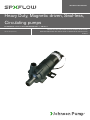
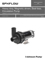
Heavy Duty, Magnetic driven, Seal-less,
Circulating pumps
FLANGED TO 12/24/32 V DC MOTOR CM10P7-1, CM30P7-1
IB-301 R08 (05/2020)

Recreational Craft Directive 94/25/EEC
ISO 8846: 1990/Small Craft - Electrical devices - Protection against ignition of surrounding flammable gases
(ISO 10133: 1994/Small Craft -Electrical systems - Extra low-voltage DC installations)
Electromagnetic Compatibility Directive 2004/108/EC
EN55014-1: 2006 Electromagnetic compatibility –
Requirements for household appliances, electric tools and similar apparatus – Part 1:Emission
EN55014-2: 1997 +A1: 2001 Electromagnetic compatibility –
Requirements for household appliances, electric tools and similar apparatus – Part 2:Immunity.
EN61000-6-3: 2007 Electromagnetic compatibility (EMC) –
Part 6-3: Generic standards – Emission standard for residential, commercial and light-industrial environments.
2004/104/EC: 2004 Annex1; paragraph 6.5, 6.6, 6.8 and 6.9.
Made by SPX FLOW Johnson Pump
RELIABILITY ON BOARD
-SINCE 1968-
Index - Indice
Svenska .....................................................................................................................................3
English ....................................................................................................................................... 5
Deutsch .....................................................................................................................................7
Français ..................................................................................................................................... 9
Español ................................................................................................................................... 13
Italiano ................................................................................................................................... 15
Besök www.spxflow.com/johnson-pump-marine för mer information om vår världsomspännande organisation, våra godkännanden, certifieringar och lokala representan-
ter. SPX FLOW, Inc. förbehåller sig rätten att ändra design och material utan föregående avisering. Designelement, konstruktionsmaterial och dimensioner som beskrivs
i denna bulletin gäller endast som information och skall alltid bekräftas skriftligt för att vara gällande.
For more information about our worldwide locations, approvals, certifications, and local representatives, please visit www.spxflow.com/johnson-pump-marine. SPX
FLOW, Inc. reserves the right to incorporate our latest design and material changes without notice or obligation. Design features, materials of construction and dimen-
sional data, as described in this bulletin, are provided for your information only and should not be relied upon unless confirmed in writing.
Für weitere Informationen über unsere weltweiten Standorte, Zulassungen, Zertifizierungen und unsere Vertreter vor Ort, besuchen Sie bitte unsere Webseite:
www.spxflow.com/johnson-pump-marine. Die SPX FLOW, Inc. behält sich das Recht vor, die neuesten Konstruktions- und Werkstoffänderungen ohne vorherige
Ankündigung und ohne Verpflichtung hierzu einfließen zu lassen. Konstruktive Ausgestaltungen, Werkstoffe sowie Maßangaben, wie sie in dieser Mitteilung beschrie-
ben sind, sind nur zur Information. Alle Angaben sind unverbindlich, es sei denn, sie wurden schriftlich bestätigt.
Pour plus d’information sur nos succursales internationales, nos approbations, nos certifications et nos représentants locaux, veuillez consulter notre site Internet au
www.spxflow.com/johnson-pump-marine. SPX FLOW, Inc. se réserve le droit d’incorporer nos plus récents concepts ainsi que tout autre modification importante sans
préavis ou obligation. Les éléments décoratifs, matériaux de construction et les données dimensionnelles, tels qu’énoncés dans ce communiqué, sont fournis pour
votre information seulement et ne doivent pas être considérés comme officiels à moins d’avis contraire par écrit.
Para más información sobre nuestras oficinas a nivel mundial, aprobaciones, certificaciones y representantes locales, por favor visite
www.spxflow.com/johnson-pump-marine. SPX FLOW, Inc. se reserva el derecho de incorporar nuestro diseño más reciente y cambios materiales sin necesidad de
notificación previa u obligación de ningún tipo. Características de diseño, materiales de construcción y dimensiones, tal y como están descritas en este boletín, son
proporcionadas sólo con fines informativos y no deben ser usados como referencia a menos que sean confirmados por escrito.
Per ottenere maggiori informazioni sulle nostre sedi nel mondo, autorizzazioni, certificazioni, e rappresentanti locali, potete visitare il sito
www.spxflow.com/johnson-pump-marine. La SPX FLOW, Inc. si riserva il diritto di apportare cambiamenti ai propri design e materiali senza preavviso o vincolo. Le
caratteristiche del design, i materiali di costruzione e i dati dimensionali, così come descritti nel presente bollettino, sono forniti solo per vostra informazione e non
saranno oggetto di obbligazione salvo autorizzazione confermata per iscritto.

3
Översättning av originalinstruktionerna
> Svenska
Typiska användningsområden
• Cirkulation av vatten/glykolblandning i
värmarsystem för bilar, båtar, husvagnar
etc.
• Cirkulation vid kylning av färskvatten i
fordon.
• Allround-pump där självsugningsför-
måga inte krävs.
Teknisk beskrivning
Pumphus: Glasfiberförstärkt plast
(PPA, GF 30%)
Axel: Rostfritt stål
Slitbricka: Rostfritt stål
O-ring: EPDM
Pumphjul: Stomme: Glasfiber förstärkt
plast (PPS, GF 40%)
Magnet: Ferrit
Bussning: Hartsbundet kol
Magnethus: Glasfiberförstärkt plast
(PSU, GF 30%)
Motorgavel: Glasfiberförstärkt plast
(PA66, GF 30%)
Statorrör: Stål, järn-zinkbehandlat,
svartkromaterat
Motortopp: Glasfiberförstärkt plast
(PA66, GF 30%)
Skruv: Stål, järn-zinkbehandlad,
svartkromaterad
Motor: Kullagrad permanent magnet-
motor, 12/24 V
Motorfäste: Aluminium, lackerat
Skyddsform: IP67 (DIN40050)
Anslutning: CM10: 16 alt 20 mm slang
CM30: 20 mm slang
Radioavstörd: EN55014
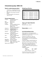
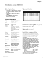
Cirkulationspump CM10/30
Modellspecifikation
Pumptyp Best nr Anslutning
CM10P7-1, 12 V 10-24501-03 16 mm (5/8")
CM10P7-1, 24 V 10-24501-04 16 mm (5/8")
CM10P7-1, 12 V 10-24502-03 20 mm (3/4")
CM10P7-1, 24 V 10-24502-04 20 mm (3/4")
CM30P7-1, 12 V 10-24503-03 16 mm (5/8")*
CM30P7-1, 24 V 10-24503-04 16 mm (5/8")*
CM30P7-1, 12 V 10-24504-03 20 mm (3/4")
CM30P7-1, 24 V 10-24504-04 20 mm (3/4")
* CM30P7-1 med 16 mm anslutning på förfrågan
Tryck- och kapacitetsdata
(se sid 18)
Baserat på vatten vid 20°C
Reservdelar (se sid 17)
Installationsföreskrifter
CM-pumparna är normalsugande centri-
fugalpumpar och ska monteras med tillrinning
alternativt fyllas upp före start.
Pumpen ska inte köras torr, även om
den tål en kortare tids torrkörning. Max
torrkörningstid 30 min. Obs! Oljud uppstår
vid torrkörning.
Pumpen har medurs rotationsriktning, sett
framifrån mot pumphuset (se rotationspil).
Motorerna är konstruerade för kontinuerlig
drift och för en spänningsvariation på
± 20%. Kapacitetsdata (sid 18) är vid
nominell spänning. Överspänning reducerar
livslängden.
Temperaturområden:
Vätska: -40° – +100°C
Omgivning: -40° – +70°C
Max systemtryck: 2,5 bar.
Pumparna får ej användas till förorenade
vatten som innehåller fasta partiklar.

4Översättning av originalinstruktionerna
> Svenska
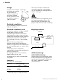
+
–
Obs! Före installation med elektriskt
styrsystem kontrollera att utrustningen
som ska användas har tillräcklig effekt för
motorns strömstyrka.
Varning
Pumpa inte bensin, lösningsmedel, thinner
eller andra lättantändliga vätskor. Om
korrosiva vätskor måste pumpas, skölj
pumpen med vatten efter varje användning.
Viktigt!
Pumparna kan installeras i valfritt läge,
horisontellt eller vertikalt.
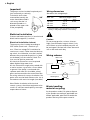
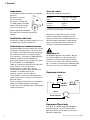
För att undvika luft-
fickor bör utloppet vid
horisontellt montage
vändas uppåt eller så att
det befinner sig på övre
sidan av pumpen.
Elektrisk installation
Anslut röd kabel till pluspol (+) och svart
kabel till minuspol (-).
Elektrisk installation i båt
Pumpen ska installeras i enlighet med ISO
10133 (Båtar - Elektriska system -
Klenspänningsinstallationer för likström).
Andra elektriska styrdon, reläer och övriga
strömbrytare ska placeras mellan pump och
batteriets pluspol (på den röda kabeln).
Obs! Säkringen ska vara av gnistskyddad
typ.
Alla elektriska anslutningar måste
placeras ovanför högsta slagvattennivå.
Kabelanslutningarna bör vara avtätade med
ett marint tätningsmedel, t ex vaselin, silikon
eller fett.
Om pumpen ansluts med separat
jordningskabel ska denna vara gul/grön och
anslutas till motorns fot.
Se kopplingsschema för rätt installation.
Negativ ledare ska vara svart.
Välj kabeldimension efter total kabellängd
enligt tabell.
90°
Kopplingsschema
Pump
Säkring Strömbrytare
Max 0,2
m
Röd
Svart
Grön/gul
Kabelarea
(baserat på 3% spänningsfall)
Kabelarea Max kabellängd*
12 V 24 V
1,0 mm2 11 m 44 m
1,5 mm2 16,5 m
2,5 mm2 27,4 m
* Kabellängden är det totala avståndet från
batteriet till pumpen och tillbaka till batteriet.
Avfallshantering/
materialåtervinning
Vid avfallshantering ska produkten lämnas
för destruktion/återvinning enligt gällande
lagstiftning. Vid tillämpliga fall demonteras
och sorteras produkten i ingående
materialfraktioner.

5
Original instructions
> English
Typical applications
• Circulation of water/antifreeze in heating
system for cars, boats, recreation vehic-
les, etc.
• Circulation for cooling fresh water in
vehicles.
• All-round pumps wherever self-
priming is not essential.
Technical description
Body: Glass reinforced plastic
(PPA, GF 30%)
Shaft: Stainless steel
Wear plate: Stainless steel
O-ring: EPDM
Impeller: Body: Glass reinforced
plastic (PPS, GF 40%)
Magnet: Ferrit
Bearing: Resin-bonded
carbon
Magnet Glass reinforced plastic
housing: (PSU, GF 30%)
Motor flange: Glass reinforced plastic
(PA66, GF 30%)
Polletube: Steel, el-plated zink-iron,
black chromated
Motor end: Glass reinforced plastic
(PA66, GF 30%)
Screws: Steel, el-plated zink-iron,
black chromated
Motor: Ball bearing permanent
magnet motor, 12/24 V
Motorbracket: Aluminium, painted
Motor
protection: IP67 (DIN40050)
Connection: CM10: 16 alt 20 mm hose
CM30: 20 mm hose
Radio distur-
bance shielded:EN55014
Cirkulation pump CM10/30
Pressure and capacity data (see page 18)
Based on water at 20°C (68°F)
Spare parts (see page 17)
Installation recommendation
The CM-series pumps are normal-priming
centrifugal pumps and should be mounted in
a manner that ensures that they are always
flooded or else be primed before being
switched on.
The pump should not be run dry, even if it
stands a shorter time of dry running. Max dry
running 30 min. Note! Noice at dry running.
The direction of rotation of the pump is clock-
wise, viewed from the front towards the body
(see rotation arrow).
The motors are made for continous duty and
for voltage fluctuation of ± 20%. Capacity
data (page 18) is for the rated voltage. Over-
voltage reduces component life.
Temperature ranges:
Liquid: -40° – +100°C
Ambient: -40° – +70°C
Max system pressure: 2.5 bar.
The pumps should not be used for soiled
water containing hard particles.
Type specification
Pump type Art. No. Connection
CM10P7-1, 12 V 10-24501-03 16 mm (5/8")
CM10P7-1, 24 V 10-24501-04 16 mm (5/8")
CM10P7-1, 12 V 10-24502-03 20 mm (3/4")
CM10P7-1, 24 V 10-24502-04 20 mm (3/4")
CM30P7-1, 12 V 10-24503-03 16 mm (5/8")*
CM30P7-1, 24 V 10-24503-04 16 mm (5/8")*
CM30P7-1, 12 V 10-24504-03 20 mm (3/4")
CM30P7-1, 24 V 10-24504-04 20 mm (3/4")
* CM30P7-1 with 16 mm connection on request

6Original instructions
> English
* The wire length is the total distance from the
battery to the pump and back to the battery.
Caution
Do not pump gasoline, solvents, thinners,
highly concentrated or organic acids. If cor-
rosive fluids must be handled, pump life will
be prolonged if flushed with water after each
use or after each work day.
Wiring scheme
Wiring dimensions
(based on 3% voltage drop)
Wire size Max wire lenght in mm*
12 V 24 V
1.0 mm2 11 m 44 m
1.5 mm2 16.5 m
2.5 mm2 27.4 m
Important!
The pumps can be installed in optional posi-
tion, horizontally or vertically.
To avoid air-locks when
mounted horizontally, the
outlet should be turned in
such a way that the it is
directed upwards or is
placed on the upper side
of the pump body.
Elektrical installation
Connect red lead to positive (+) terminal and
black lead to negative (-) terminal.
Electrical installation in boat
The pump must be installed according to
ISO 10133 (Small craft - Electrical sys-
tem - Extra low voltage DC installation for
continuous current). Other electrical devices,
eg switch, circuit breaker, must be installed
between the pump and the positive (+) lead
on the battery (on the red wire). Note: The
fuse must be ignition protected.
All electrical connections must be placed
above highest bilge water level.
All wire connections ought to be sealed with
a marine sealant, e g vaseline, silicon rubber
or grease. If the pump is connected with
separate earth lead, this should be yellow/
green and connected to the motor base.See
the wiring scheme for correct installation. Ne-
gative wire must be black.Choose wire size in
accordance with total wire lenght (see table).
Note: Before installation with electrical
control systems, check that equipment to be
used is of sufficient rated capacity to accept
ampere draw of motor.
90°
+
–Terminal
fuse
Switch
Pump
Max 0.2 m
Red
Green/yellow
Black
Waste handling
material recycling
At the products end of life, please dispose
of the product according to applicable law.
Where applicable, please disassemble the
product and recycle the parts material.

7
Übersetzung der Original-Betriebanleitungen
> Deutsch
Umwälzpumpe CM10/30
Typische Einsatzbereiche
• Umwälzpumpe für Wasser, Frost-
schutzgemisch in Heizanlagen für
Kraftfahrzeuge, Boote, Wohnwagen
usw.
• Umwälzpumpe zum Kühlen des
Frischwassers in Fahrzeugen
• Allzweck-Pumpe, für Einsätze wo
keine Selbstansaugung erforderlich ist.
Technische Beschreibung
Pumpengehäuse: Glasfaserverstärkter
Kunststoff (PPA,
GF 30 %)
Welle: Edelstahl
Verschleißplatte: Edelstahl
O-Ring: EPDM
Laufrad: Körper: Glasfaser-
verstärkter Kunststoff
(PPS, GF 40 %)
Magnet: Ferrit
Lager: Harzgebun-
dener Kohlenstoff
Magnetgehäuse: Glasfaserverstärkter
Kunststoff (PSU,
GF 30 %)
Motorenflansch: Glasfaserverstärkter
Kunststoff (PA66,
GF 30 %)
Motorengehäuse: Stahl, eisenzink-
behandelt, schwarz-
chromatiert
Motorenabdeckung: Glasfaserverstärkter
Kunststoff (PA66,
GF 30 %)
Schrauben: Stahl, eisenzink-
behandelt, schwarz-
chromatiert
Motor: Wälzgelagert Dauer-
magnetmotor, 12/24 V
Motorträger: Aluminium, lackiert
Schutzart: IP67 (DIN40050)
Anschluß: CM10: Für Schlauch
ø 16 bzw. 20 mm
CM30: Für Schlauch
ø 20 mm
Funkenentstört: EN55014
Modellbeschreibung
Druck- und Leistungsdaten
(Siehe Seite 18)
Die Angaben beziehen sich auf Wasser-
temperatur bei 20°C.
Ersatzteilliste (Siehe Seite 17)
Einbauvorschriften
Die CM-Pumpen sind normalansaugende
Kreiselpumpen und müßen vor der Inbetrieb-
nahme mit der Förderflüssigkeit aufgefüllt
werden.
Die Pumpen dürfen nicht trocken-laufen.
Ein kurzzeitiger Trockenlauf beschädigt die
Pumpe nicht. Beachten Sie daß mehr als 30
Minuten Trockenlauf die Pumpe unbrauch-
bar macht. Hinweis! Beim Trockenlauf sind
Laufgeräusche hörbar.
Achtung: Die Pumpe muß immer in Drehrich-
tung laufen.
Die Pumpen sind für Dauerbetrieb sowie
einem Spannungsfall von ±20° gefertig.
Temperaturbereiche:
Flüssigkeit: -40 °C bis +100 °C
Umgebung: -40 °C bis +70 °C
Max. System-Druck: 2,5 bar
Die Pumpen dürfen nicht für Schmutz-
wasser, welches grobe Fremdpartikel enthält,
verwendet werden.
Pumpentyp Artikel Nr. Anschluß
CM10P7-1, 12 V 10-24501-03 16 mm (5/8")
CM10P7-1, 24 V 10-24501-04 16 mm (5/8")
CM10P7-1, 12 V 10-24502-03 20 mm (3/4")
CM10P7-1, 24 V 10-24502-04 20 mm (3/4")
CM30P7-1, 12 V 10-24503-03 16 mm (5/8")*
CM30P7-1, 24 V 10-24503-04 16 mm (5/8")*
CM30P7-1, 12 V 10-24504-03 20 mm (3/4")
CM30P7-1, 24 V 10-24504-04 20 mm (3/4")
* CM30P7-1 mit 16 mm Anschluß auf Anfrage

8Übersetzung der Original-Betriebanleitungen
> Deutsch
Anmerkung: Bei der Installation mit elek-
trischem Steuersystem ist sicher-
zustellen, daß die Ausrüstung für die Stro-
maufnahme des Motors ausgelegt ist.
Achtung
Kein Benzin, Lösungsmittel, Verdünnungs-
mittel, organische oder hochkonzentrierte
Säuren pumpen. Wenn ätzende Flüssigkeiten
gepumpt werden müssen, kann die Standzeit
der Pumpe verlängert werden, wenn nach
jedem Gebrauch oder mindestens einmal pro
Tag mit Wasser nachgespült wird.
Schaltplan
Tabelle Kabelanschlüsse
(basierend auf 3% Spannungsverlust)
Kabel- Max. Kabellänge*
querschnitt
12 V 24 V
1,0 mm2 11 m 44 m
1,5 mm2 16,5 m
2,5 mm2 27,4 m
* Die Kabellänge ist die komplette Länge von der
Batterie zur Pumpe und zurück zur Batterie.
Wichtig!
Die Pumpen können in jeder beliebigen
Arbeitsstellung eingebaut
werden, waagerecht oder
senkrecht.
Um die Bildung von
Luftsäcken zu vermeiden,
ist der Pumpenauslaß
bei waagerechter
Montage nach oben zu
drehen oder so auszurichten
das er sich an der oberen Seite der Pumpe
befindet.
Elektrischer Anschluß
Das rote Kabel an den Pluspol (+), das
schwarze Kabel an den Minuspol (-).
Elektrische Installation im Boot
Die Pumpe muß nach den Normregeln von
ISO10133 (für Boote - Elektro-systeme
von - extra niedriger Spannung bei Gleich-
strominstallation - für gleichmäßigen Strom-
fluß) installiert werden. Weitere elektrische
Komponenten, wie Schalter, Stromkreisunter-
brecher, müssen zwischen der Pumpe und
der positiven (+) Leitung (rot) der Batterie
installiert werden. Achtung: Die Sicherung
muß funkengeschützt sein.
Alle elektrischen Anschlüsse müssen immer
oberhalb des Wasserniveaus
angebracht werden.
Kabelanschlüsse müssen mit einem
Spritzwassergeschütztem Dichtungsmittel
abgedichtet werden, z.B. Vaseline, Silikon
oder Fett.
Wenn die Pumpe mit einer separaten Erdlei-
tung versehen ist, gelb/grün, muß diese mit
der Motorhalterung verbunden sein.
Zur korrekten Installation beachten Sie
bitte den Schaltplan unten. Minus-leitung
Schwarz.
Beachten Sie die Kabelquerschnitte im
Zusammenhang mit der erfoderlichen Kabel-
länge.
90°
+
–
Pumpe
Haupt-
sicherung
Schalter
Max. 0,2 m
Rot
Schwarz
Gelb/Grün
Entsorgung/Recycling
Nach Lebensdauerende entsorgen Sie die
Pumpe nach den örtlichen Vorschriften.
Nach Möglichkeit demontieren Sie Teile
der Pumpe um sie dem Recycling-Process
zuzuführen.

9
Traduction du manuel d'instruction d'origine
> Français
Domaines d’utilisation typiques
• Circulation d’eau/mélange de glycol
dans le système de chauffage pour les
voitures, les bateaux, les caravanes, etc.
• Circulation d’eau douce dans les véhicules.
• Pompe universelle quand l’autoamorçage
n’est pas nécessaire.
Description technique
Corps de pompe: Plastique renforcé de
fibres de verre (PPA,
GF 30%)
Axe: Acier inoxydable
Rondelle d’usure: Acier inoxydable
Joint torique: EPDM
Turbine: Corps: plastique renforcé
de fibres de verre (PPS,
GF 40%)
Aimant: ferrite
Bague: alliage, carbone/résine
Carter d’aimant: Plastique renforcé de
fibres de verre (PSU,
GF 30%)
Flasque moteur: Plastique renforcé de
fibres de verre
(PA66, GF 30%)
Enveloppe moteur: Acier zingué, chromé
noir
Tête de moteur: Plastique renforcé de
fibres de verre
(PA66, GF 30%)
Vis: Acier zingué, chromé
noir
Moteur: Moteur magnétique
permanent 12/24 V
monté sur roulement
à billes
Fixation moteur: Aluminium, laquée
Protection: IP67 (DIN40050)
Raccord: CM10: flexible de
10 ou 20 mm
CM30: flexible de 20 mm
Antiparasite radio: EN55014
Les pompes ne doivent pas être utilisées pour
Pompe de circulation CM10/30
Caractéristiques moteur
Caractéristiques de pression
et de débit (voir page 19)
Basées sur de l’eau à +20°C
Pièces de rechange (voir page 17)
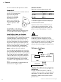
Prescriptions d’installation
Les pompes CM sont des pompes centrifu-
ges qui doivent être installées en charge ou
être amorcées avant le démarrage.
La pompe ne doit pas fonctionner à sec de
façon continue. Cependant elle peut sup-
porter au maximum 30 minutes de fonction-
nement à sec. Dans ce cas, le niveau de bruit
peut être plus élevé.
La pompe tourne dans le sens d’horloge,
vue de devant vers le corps de pompe (voir
flèche de rotation).
Les moteurs sont prévus pour utilisation
continue et pour variations de tension de ±
20%. Le tableau des débits (page 19) cor-
respond a la tension nominale les surtentions
reduisent la durée de vie des composants.
Plages de température:
Température de liquide: -40°C à +100°C
Température ambiante: -40°C à +70°C
Pression maximum: 2,5 bar
Modèle Référence Raccord
CM10P7-1, 12 V 10-24501-03 16 mm (5/8")
CM10P7-1, 24 V 10-24501-04 16 mm (5/8")
CM10P7-1, 12 V 10-24502-03 20 mm (3/4")
CM10P7-1, 24 V 10-24502-04 20 mm (3/4")
CM30P7-1, 12 V 10-24503-03 16 mm (5/8")*
CM30P7-1, 24 V 10-24503-04 16 mm (5/8")*
CM30P7-1, 12 V 10-24504-03 20 mm (3/4")
CM30P7-1, 24 V 10-24504-04 20 mm (3/4")
* CM30P7-1 avec connexion 16mm sur demande

10
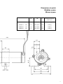
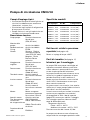
44
50
ø B
röd/red/rot/rouge/rojo/rosso (+)
svart/black/schwarz/noir/negro/nero (–)
min 50
133
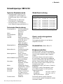
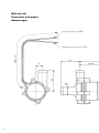
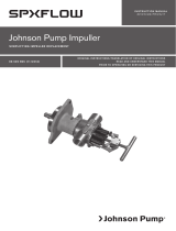
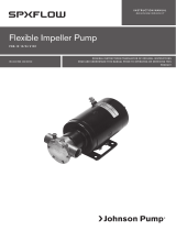
Mått och vikt
Dimensions and weight
Abmessungen
C
260 ± 10

11
ø A
ø B
46
53
68
20
9
34.5
ø A ø B C Vikt/Weight/Gewicht
Poids, Peso
CM10P7-1 ø 16 17.7 16.2 (5/8") 17.3 0.53 kg
CM10P7-1 ø 20 21.4 20.0 (3/4") 15.8 0.53 kg
CM30P7-1 ø 16 17.7 16.2 (5/8") 17.3 0.60 kg
CM30P7-1 ø 20 21.4 20.0 (3/4") 15.8 0.60 kg
Dimensions et poids
Medidas y peso
Misura e peso
133

12 Traduction du manuel d'instruction d'origine
> Français
des eaux contenant des particules solides.
Important!
Les pompes peuvent être installées verticale-
ment or ou horizontalement.
Pour éviter des poches
d’air avec un montage
horizontal, la sortie doit
être orientée vers le
haut ou vers la droite de
façon à toujours être dans
la partie supérieure de la
pompe.
Installation électrique
Brancher le câble rouge à la borne positive
(+) et le câble noir à la borne négative (-).
Installation dans un bateau
La pompe doit être installée suivant les
recommandations ISO 10133 (Petits bateaux,
système électrique, installation à courant
continu de très basse tension). Tous les ac-
cessoires électriques tels que: Interrupteurs,
disjoncteurs, doivent être installés entre la
pompe et le + de la batterie (sur le fil rouge).
Nota: Le fusible doit être "antideflagrant".
Tous les raccords électriques doivent être
placés au-dessus du niveau maximal
d’eau.
Les raccords de câble doivent être étanchés
avec un produit d’étanchéité marin, par exem-
ple de la vaseline, du silicone ou de la graisse.
Si un fil de masse est raccordé à la pompe,
il doit être de couleur Jaune/Vert et doit être
connecté aux pattes de fixation du moteur.
Voir schéma électrique pour une correcte
installation. Le fil négatif doit être de couleur
noire.
Choisir la section des fils d'alimentation en
fonction de leur longeur totale.
90°
Section des fils
(basé sur une chute de tension de 3%)
Section Longueur maxi*
12 V 24 V
1,0 mm2 11 m 44 m
1,5 mm2 16,5 m
2,5 mm2 27,4 m
* La longueur totale correspond à la distance de
la batterie à la pompe et du retour de la pompe
à la batterie. batterie.batterie.
Important: Avant toute installation avec un
système de commande électrique, vérifier
que le matériel qui va être utilisé, peut sup-
porter le courant demandé par le moteur.
Attention
Ne pas pomper d’essence, de solvants,
de diluants, d’acides organiques ou trés
concentrés. Dans le cas d’un fonctionnement
avec des liquides corrosifs, un rinçage à l’eau
après chaque utilisation ou après chaque
journée de travail prolongera sa durée de vie.
Schéma électrique
Pompe
Fusible
principal Interrupteur
Maxi
0,2 m
Rouge
Noir
Vert/jaune
+
–
Gestion des déchets/recyclage des
matériaux
Lorsque le matériel arrivera en fin de vie,
veuillez le mettre au rebut en fonction des lois
applicables. Lorsque c'est possible, veuillez
démonter le matériel et recycler les pièces
pouvant l'être

13
Traducción de instrucciones originales
> Español
Aplicaciones más usuales
• Circulación de agua/mezcla de glicol en
sistemas de calefacción de vehículos,
embarcaciones, remolques, caravanas,
etc.
• Circulación en la refrigeración por
agua dulce en vehículos.
• Bomba de uso general en aplicaciones
que no requieren capacidad auto-
aspirante.
Descripción técnica
Cuerpo Plástico reforzado con fibra
de la bomba: de vidrio (PPA, GF 30%)
Eje: Acero inoxidable
Arandela
de desgaste: Acero inoxidable
Aro tórico: EPDM
Impulsor: Cuerpo: Plástico reforzado
con fibra de vidrio
(PPS, GF 40%)
Imán: Ferrita
Casquillo: Carbonoresina
Caja imán: Plástico reforzado con fibra
de vidrio (PSU, GF 30%)
Tapa motor: Plástico reforzado con fibra
de vidrio (PA66, GF 30%)
Tubo estátor: Acero, electrozincado,
cromado negro
Tope del motor: Plástico reforzado con fibra
de vidrio (PA66, GF 30%)
Tornillos: Acero, hierro zincado,
cromado negro
Motor: De imán permanente,
cojinetes de bolas,
12/24 V
Fijaciones motor: Aluminio, lacado
Forma de
protección: IP67 (DIN40050)
Conexiones: CM10: manguera de
16 o 20 mm
CM30: manguera de 20 mm
Protección antiparásitos
radio: EN55014
Bomba de circulación CM10/30
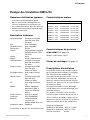
Especificación de modelos
Tipo de bomba Pieza No Conexión
CM10P7-1, 12 V 10-24501-03 16 mm (5/8")
CM10P7-1, 24 V 10-24501-04 16 mm (5/8")
CM10P7-1, 12 V 10-24502-03 20 mm (3/4")
CM10P7-1, 24 V 10-24502-04 20 mm (3/4")
CM30P7-1, 12 V 10-24503-03 16 mm (5/8")*
CM30P7-1, 24 V 10-24503-04 16 mm (5/8")*
CM30P7-1, 12 V 10-24504-03 20 mm (3/4")
CM30P7-1, 24 V 10-24504-04 20 mm (3/4")
* CM30P7 1 con conexión de 16 mm bajo pedido
Datos de presión y caudal
(ver página 19)
Basados con agua a 20 °C
Repuestos (ver página 17)
Instrucciones instalación
Las bombas CM son centrífugas de aspira-
ción normal y han de montarse de forma que
reciban agua o que se ceben antes de la
puesta en marcha.
Las bombas no deben funcionar en seco,
aunque soporten este tipo de funcionamiento
durante algún tiempo.
El tiempo máximo de funcionamiento en seco
no ha de ser superior a 30 minutos. Nota: Al
funcionar en seco la bomba produce ruidos.
El sentido de rotación es a la derecha, con el
cuerpo de bomba visto frontalmente (véase
la flecha indicadora).
Los motores son de funcionamiento contínuo
y permite una variación de
± 20%. Curvas de caudales según esquema
(página 19). El sobrevoltaje reduce la vida de
la bomba.
Gamas de temperatura:
Líquido: -40° - +100 °C
Ambiente: -40° - +70 °C
Presión máxima: 2,5 bar
Las bombas no deben utilizarse en aguas
que contengan partículas sólidas.

14 Traducción de instrucciones originales
> Español
Observación: Antes de instalar sistemas
eléctricos de control, comprobar que el
equipo a utilizar tiene la capacidad nominal
necesaria para acomodar el amperaje del
motor. La tensión baja tiene como conse-
cuencia el recalentamiento del motor.
Advertencia
No bombear gasolina, disolventes, diluyen-
tes, ácidos orgánicos o de concentración
elevada. Si es necesario bombear fluidos
corrosivos, la vida útil de la bomba se prote-
ge si se hace correr agua por la bomba cada
vez que se la utiliza o al final de la jornada.
Esquema eléctrico
Importante
Las bombas pueden instalarse en cualquier
posición,
horizontal o vertical.
En la instalación
horizontal conviene que
la salida quede orientada
hacia arriba o de manera
que se encuentre en la
parte superior de la bomba.
Se evitará así la formación de bolsas
de aire.
Instalación eléctrica
Conectar el cable rojo al borne positivo (+) y
el cable negro al borne negativo (-).
Instalación en embarcaciones
La bomba debe instalarse según ISO 10133
(Pequeñas embaracaciones - Artículos eléc-
tricos. Bajo voltaje de CC para instalaciones
de corriente contínua.) Los demás disposi-
tivos eléctricos, interruptor, magnetotérmico,
deberán instalarse entre la bomba y el
positivo de la bateria (en el cable rojo). Nota:
El fusible debe ser antideflagante.
Todas las conexiones eléctricas han de colo-
carse sobre el nivel más alto que
pueda alcanzar el agua de la sentina.
Las conexiones de los cables han de estar
selladas con sellador marino; por
ejemplo, vaselina, silicona o grasa.
Si la bomba se instala con toma de tierra, el
cable será amarillo y verde y se conecta a la
base del motor.
Para su correcta instalación, ver el esquema
eléctrico. El cable negativo será negro.
Instalar la sección del cable que corresponda
según la distancia.
90°
Tabla de cables
(Basada en caida de voltaje 3%)
Sección Largo máx * del cable
cable 12 V 24 V
1,0 mm2 11 m 44 m
1,5 mm2 16,5 m
2,5 mm2 27,4 m
* El largo del cable, es la distancia total desde la
bateria a la bomba y regreso a la bateria.
Bomba
Fusible
principal Interruptor
Max.
0,2 m
Rojo
Negro
Verde/amarillo
+
–
Desguace/Reciclado
Al final de la vida del equipo disponga de
este de acuerdo a la ley. Donde sea de
aplicación desmonte el equipo y recicle los
diferentes materiales.

15
Traduzione delle istruzioni originali
> Italiano
Campi d’impiego tipici:
• Circolazione di acqua/miscela di glicole nei
circuiti di riscaldamento per autovetture,
imbarcazioni, roulottes, ecc.
• Circolazione negli impianti di refrigerazione
di acqua pura nei veicoli.
• Pompa multiuso in tutti gli impianti che non
richiedono la funzione autoadescante.
Descrizione tecnica
Corpo pompa: Plastica rinforzata con
fibra di vetro
(PPA, GF 30%)
Alberino della
pompa: Acciaio inossidabile
Rondella antiusura: Acciaio inossidabile
O-ring: EPDM
Girante: Struttura: Plastica
rinforzata con fibra di
vetro (PPS, GF 40%)
Magnete: Ferrite
Boccola: Resina
carbonica
Alloggiamento Plastica rinforzata con
magnete: fibra di vetro
(PPS, GF 30%)
Parete motore: Plastica rinforzata con
fibra di vetro
(PA66, GF 30%)
Tubo dello statore: Acciaio, trattato al
ferro-zinco e cromatato
nero
Involucro motore: Plastica rinforzata con
fibra di vetro
(PA66, GF 30%)
Vite: Acciaio, trattato al
ferro-zinco e cromatato
nero
Motore: Motore a magnete
permanente supportato
da cuscinetti, 12/24 V
Attacchi motore: Alluminio verniciato
Tipo di protezione: IP67 (DIN40050)
Connessioni: CM10: Tubo flessibile
da 16 oppure 20 mm
CM30: Tubo flessibile
da 20 mm
Protezione disturbi
radio: EN55014
Pompa di circolazione CM10/30
Specifiche modelli
Tipo di pompa Art. No. Collegamento
CM10P7-1, 12 V 10-24501-03 16 mm (5/8")
CM10P7-1, 24 V 10-24501-04 16 mm (5/8")
CM10P7-1, 12 V 10-24502-03 20 mm (3/4")
CM10P7-1, 24 V 10-24502-04 20 mm (3/4")
CM30P7-1, 12 V 10-24503-03 16 mm (5/8")*
CM30P7-1, 24 V 10-24503-04 16 mm (5/8")*
CM30P7-1, 12 V 10-24504-03 20 mm (3/4")
CM30P7-1, 24 V 10-24504-04 20 mm (3/4")
* CM30P7-1 con attacco 16 millimetri a richiesta
Dati tecnici relativi a pressione
e portata (Vedi página 19)
Basati su impiego di acqua a 20°C
Parti di ricambio (Vedi página 17)
Istruzioni per il montaggio
Le pompe CM sono pompe centrifughe ad
aspirazione normale e devono essere allac-
ciate a tubature in presenza di flusso oppure
essere riempite prima dell’avviamento.
La pompa non deve essere azionata a secco,
anche se è in grado di sopportare un breve
periodo d’esercizio in tale condizione. Il
tempo massimo d’esercizio a secco è di 30
minuti. N.B.! Il funzionamento a secco pro-
duce notevole rumorosità.
La girante ruota in senso orario, vista anterior-
mente verso il corpo pompa (vedere la freccia
che indica il senso di rotazione).
I motori sono costruiti per lavorare in corrente
continua e per sopportare una variazioni
di voltaggio del ± 20%. I dati di capcaità
(página 19) servono per stabilire il voltaggio.
Con voltaggio superiore al dovuto riduce i
tempi di durata delle parti.
Temperature d’esercizio:
Fluido: -40°C + 100°C
Ambiente circostante: -40°C + 70°C
Pressione massima del sistema: 2,5 bar.
Le pompe non devono essere utilizzate con
acque luride che contengano particelle solide.

16 Traduzione delle istruzioni originali
> Italiano
* La lunghezza del filo si trova calcolando la
distanza dalla batteria alla pompa e ritorno.
Si raccomanda l'utilizzo di un fusibile che abbia
un collegamento elettrico che parte dall'alimen-
tazione principale fino ad arrivare al
pressostato. Si consiglia inoltre di montare il
fusibile il più vicino possibile alla fonte di
alimentazione principale (max 0,20 mt).
batteriet.
Cautela
Non pompare benzina, solventi, diluenti, acidi
altamente concentrati od organici. Se è necessa-
rio trattare fluidi corrosivi, la durata della pompa
potrà essere prolungata sciacquandola con
acqua dopo ciasun uso o dopo ogni giorno di
lavoro.
Schema elettrico
Importante!
Le pompe possono essere montate sia in
posizione orizzontale
che verticale, come si
preferisce.
Per evitare però il
formarsi di bolle d’aria
in caso di montaggio
orizzontale, l’uscita di
scarico va disposta verso
l’alto o comunque
in posizione sovrastante al corpo pompa.
Installazione elettrica
Collegare il cavo rosso al polo positivo (+) e
quello nero al polo negativo (-).
Nell’installazione su imbarcazioni
La pompa è costruita secondo le norme ISO
10133 (funzionamento in corrente continua
per piccolo circuiti).
Altre installazioni elettriche, interruttori ecc.,
olevoua essere montate tra la pompa e il
positivo (+) della batteria (filo rosso). Nota: Il
fusibile deve essere protetto dall'accensione.
Tutti i collegamenti elettrici vanno posti al
di sopra della linea di livello più elevata
dell’acqua di sentina.
Gli allacciamenti elettrici andrebbero isolati
mediante isolante marino, ad esempio vase-
lina, silicone o grasso.
Per il collegamento a massa della pompa,
utilizzare il filo giallo/verde (massa internazio-
nale).
Per una corretta installazione, consultare lo
schema elettrico. Il cavo del negativo deve
essere nero.
La sezione dei fili è variabile a seconda della
loro lunghezza.
Nota: Prima dell’installazione con i sistemi di
controllo elettrici, controllare che l’attrezzatura
da usare sia di capacità sufficiente da accet-
tare il consumo di ampere del motore.
90°
Pompa
Fusibile Interruttore
Max
0,2 mt
Rosso
Nero
Verde/giallo
+
–
Tabella informativa per la scelta sezione
cavi
(variazione = 3% V)
Sezione Max lunghezza del filo*
del filo 12 V 24 V
1,0 mm2 11 m 44 m
1,5 mm2 16,5 m
2,5 mm2 27,4 m
Gestione dei rifiuti/
riciclaggio dei materiali
Al termine della vita del prodotto si prega di smaltire il
prodotto secondo le leggi in vigore per queste opera-
zioni. Quando possibile, si raccomanda di smontare il
prodotto e riciclare i materiali dei componenti.

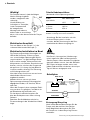
17
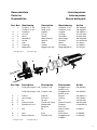
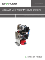
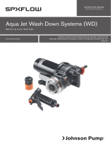
Pos Nos Benämning Description Bezeichnung Art No
1 1 Pumphus, ø 16 Body, ø 16 Gehäuse, ø 16 09-46549*)
Pumphus, ø 20 Body, ø 20 Gehäuse, ø 20 09-46550*)
2 1 Pumphjul Impeller Laufrad 09-46551**)
3 1 O-ring O-ring O-Ring 0.2173.020
4 4 Skruv Screw Schraube 0.0145.002
5 1 Motorfäste Motor bracket Motorträger 36-503-023
6 1 Bricka Washer Scheibe 01-46792-01
7 1 Axel Shaft Welle 01-46317
8 1 Packning Gasket Dichtung 01-46552
9 1 Magnethus Magnet housing Magnetgehäuse 01-35733
*) incl pos 3, 4 **) incl pos 6, 7
Pos Nos Description Descripción Descrizione Art No
1 1 Corps de pompe, ø 16 Cuerpo, ø 16 Alloggiamento 09-46549*)
pompa, ø 16
Corps de pompe, ø 20 Cuerpo, ø 20 Alloggiamento 09-46550*)
pompa, ø 20
2 1 Turbine Impulsor Girante 09-46551**)
3 1 Joint torique Aro tórico O-Ring 0.2173.020
4 4 Vis Tornillos Viti 0.0145.002
5 1 Fixation moteur Fijación del motor Attacchi motore 36-503-023
6 1 Rondelle d’usure Arandela de Rondella 01-46792-01
desgaste antiusura
7 1 Axe Eje Alberino della 01-46317
pompa
8 1 Joint Junta Guarnizione 01-46552
9 1 Boîtier d’aimant Caja del imán Alloggiamento 01-35733
magnete
*) incl pos 3, 4 **) incl pos 6, 7
Reservdelslista
Parts list
Ersatzteilliste
Liste des pièces
Lista de piezas
Elenco delle parti
1
2
3
5
4
6
7
8
9

18
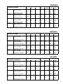
Pressure and Capacity Back pressure Flow Amperage
Bar kPa ft l/min USGPM 12 V 24 V
CM10P7-1 Hose connection 0.10 10 3.3 15.0 4.0 1.2 0.6
ø 16 mm (5/8") 0.15 15 4.9 12.0 3.2 1.1 0.55
0.20 20 6.6 7. 3 1.9 0.9 0.5
Fuse required 1.6 0.8
CM10P7-1 Hose connection 0.10 10 3.3 18.5 5.0 1.2 0.6
ø 20 mm (3/4") 0.15 15 4.9 14.5 3.9 1.1 0.55
0.20 20 6.6 9.0 2.4 1.0 0.5
Fuse required 1.6 0.8
CM30P7-1 Hose connection 0.10 10 3.3 20.0 5.3 1.9 0.9
ø 16 mm (5/8")* 0.20 20 6.6 16.0 4.2 1.75 0.8
0.30 30 9.8 7. 5 2.0 1.4 0.75
Fuse required 3.0 1.6
CM30P7-1 Hose connection 0.10 10 3.3 26.0 6.9 2.2 1.1
ø 20 mm (3/4") 0.20 20 6.6 19.5 5.2 2.0 1.0
0.30 30 9.8 9.0 2.4 1.7 0.75
Fuse required 3.0 1.6
* available on request
Druck- und Leistung Druck Fördermenge Stromverbrauch
Bar kPa ft l/min USGPM 12 V 24 V
CM10P7-1 Schlauchanschluß 0.10 10 3.3 15.0 4.0 1.2 0.6
ø 16 mm (5/8") 0.15 15 4.9 12.0 3.2 1.1 0.55
0.20 20 6.6 7. 3 1.9 0.9 0.5
Empfohlene Sicherung 1.6 0.8
CM10P7-1 Schlauchanschluß 0.10 10 3.3 18.5 5.0 1.2 0.6
ø 20 mm (3/4") 0.15 15 4.9 14.5 3.9 1.1 0.55
0.20 20 6.6 9.0 2.4 1.0 0.5
Empfohlene Sicherung 1.6 0.8
CM30P7-1 Schlauchanschluß 0.10 10 3.3 20.0 5.3 1.9 0.9
ø 16 mm (5/8")* 0.20 20 6.6 16.0 4.2 1.75 0.8
0.30 30 9.8 7. 5 2.0 1.4 0.75
Empfohlene Sicherung 3.0 1.6
CM30P7-1 Schlauchanschluß 0.10 10 3.3 26.0 6.9 2.2 1.1
ø 20 mm (3/4") 0.20 20 6.6 19.5 5.2 2.0 1.0
0.30 30 9.8 9.0 2.4 1.7 0.75
Empfohlene Sicherung 3.0 1.6
* Auf Anfrage erhältlich
Tryck- och kapacitet Tryck Flöde Strömförbr.
Bar kPa ft l/min USGPM 12 V 24 V
CM10P7-1 Slanganslutning 0.10 10 3.3 15.0 4.0 1.2 0.6
ø 16 mm (5/8") 0.15 15 4.9 12.0 3.2 1.1 0.55
0.20 20 6.6 7. 3 1.9 0.9 0.5
Rek. säkring 1.6 0.8
CM10P7-1 Slanganslutning 0.10 10 3.3 18.5 5.0 1.2 0.6
ø 20 mm (3/4") 0.15 15 4.9 14.5 3.9 1.1 0.55
0.20 20 6.6 9.0 2.4 1.0 0.5
Rek. säkring 1.6 0.8
CM30P7-1 Slanganslutning 0.10 10 3.3 20.0 5.3 1.9 0.9
ø 16 mm (5/8")* 0.20 20 6.6 16.0 4.2 1.75 0.8
0.30 30 9.8 7. 5 2.0 1.4 0.75
Rek. säkring 3.0 1.6
CM30P7-1 Slanganslutning 0.10 10 3.3 26.0 6.9 2.2 1.1
ø 20 mm (3/4") 0.20 20 6.6 19.5 5.2 2.0 1.0
0.30 30 9.8 9.0 2.4 1.7 0.75
Rek. säkring 3.0 1.6
* På begäran
ENGLISH
DEUTSCH
SVENSKA

19
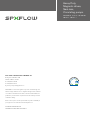
Presión y caudal Presión Caudal Amperaje
Bar kPa ft l/min USGPM 12 V 24 V
CM10P7-1 Conexión tubo 0.10 10 3.3 15.0 4.0 1.2 0.6
ø 16 mm (5/8") 0.15 15 4.9 12.0 3.2 1.1 0.55
0.20 20 6.6 7. 3 1.9 0.9 0.5
Fusible recomendado 1.6 0.8
CM10P7-1 Conexión tubo 0.10 10 3.3 18.5 5.0 1.2 0.6
ø 20 mm (3/4") 0.15 15 4.9 14.5 3.9 1.1 0.55
0.20 20 6.6 9.0 2.4 1.0 0.5
Fusible recomendado 1.6 0.8
CM30P7-1 Conexión tubo 0.10 10 3.3 20.0 5.3 1.9 0.9
ø 16 mm (5/8")* 0.20 20 6.6 16.0 4.2 1.75 0.8
0.30 30 9.8 7. 5 2.0 1.4 0.75
Fusible recomendado 3.0 1.6
CM30P7-1 Conexión tubo 0.10 10 3.3 26.0 6.9 2.2 1.1
ø 20 mm (3/4") 0.20 20 6.6 19.5 5.2 2.0 1.0
0.30 30 9.8 9.0 2.4 1.7 0.75
Fusible recomendado 3.0 1.6
* Disponible bajo pedido
Pressione e portata Pressione Portata Amperaggio
Bar kPa ft l/min USGPM 12 V 24 V
CM10P7-1 Sezione tubo 0.10 10 3.3 15.0 4.0 1.2 0.6
ø 16 mm (5/8") 0.15 15 4.9 12.0 3.2 1.1 0.55
0.20 20 6.6 7. 3 1.9 0.9 0.5
Fusibile raccomandato 1.6 0.8
CM10P7-1 Sezione tubo 0.10 10 3.3 18.5 5.0 1.2 0.6
ø 20 mm (3/4") 0.15 15 4.9 14.5 3.9 1.1 0.55
0.20 20 6.6 9.0 2.4 1.0 0.5
Fusibile raccomandato 1.6 0.8
CM30P7-1 Sezione tubo 0.10 10 3.3 20.0 5.3 1.9 0.9
ø 16 mm (5/8")* 0.20 20 6.6 16.0 4.2 1.75 0.8
0.30 30 9.8 7. 5 2.0 1.4 0.75
Fusibile raccomandato 3.0 1.6
CM30P7-1 Sezione tubo 0.10 10 3.3 26.0 6.9 2.2 1.1
ø 20 mm (3/4") 0.20 20 6.6 19.5 5.2 2.0 1.0
0.30 30 9.8 9.0 2.4 1.7 0.75
Fusibile raccomandato 3.0 1.6
* Disponibile su richiesta
Pression et débit Pression Débit Intensité
Bar kPa ft l/min USGPM 12 V 24 V
CM10P7-1 Raccord de flexible 0.10 10 3.3 15.0 4.0 1.2 0.6
ø 16 mm (5/8") 0.15 15 4.9 12.0 3.2 1.1 0.55
0.20 20 6.6 7. 3 1.9 0.9 0.5
Fusible nécessaire 1.6 0.8
CM10P7-1 Raccord de flexible 0.10 10 3.3 18.5 5.0 1.2 0.6
ø 20 mm (3/4") 0.15 15 4.9 14.5 3.9 1.1 0.55
0.20 20 6.6 9.0 2.4 1.0 0.5
Fusible nécessaire 1.6 0.8
CM30P7-1 Raccord de flexible 0.10 10 3.3 20.0 5.3 1.9 0.9
ø 16 mm (5/8")* 0.20 20 6.6 16.0 4.2 1.75 0.8
0.30 30 9.8 7. 5 2.0 1.4 0.75
Fusible nécessaire 3.0 1.6
CM30P7-1 Raccord de flexible 0.10 10 3.3 26.0 6.9 2.2 1.1
ø 20 mm (3/4") 0.20 20 6.6 19.5 5.2 2.0 1.0
0.30 30 9.8 9.0 2.4 1.7 0.75
Fusible nécessaire 3.0 1.6
* Disponible sur demande
ESPAÑOL
ITALIANO
FRANÇAIS

SPX FLOW TECHNOLOGY SWEDEN AB
Nastagatan 19, P.O. Box 1436
SE-701 14 Örebro, Sweden
P: +46 (0)19 21 83 00
F: +46 (0)19 27 23 77
E: johnson-pump.marine@spxflow.com
SPX FLOW, Inc. reserves the right to incorporate our latest design and
material changes without notice or obligation. Design features, materials
of construction and dimensionals data, as described in this bulletin, are
provided for your information only and should not be relied upon unless
confirmed in writing.
Please contact your local sales representative for product availability in
your region. For more information visit www.spxflow.com.
ISSUED 05/2020 IB-301 R08
COPYRIGHT ©2016, 2020 SPX FLOW, Inc.
Heavy Duty,
Magnetic driven,
Seal-less,
Circulating pumps
FLANGED TO 12/24/32 V DC MOTOR
CM10P7-1, CM30P7-1
-
 1
1
-
 2
2
-
 3
3
-
 4
4
-
 5
5
-
 6
6
-
 7
7
-
 8
8
-
 9
9
-
 10
10
-
 11
11
-
 12
12
-
 13
13
-
 14
14
-
 15
15
-
 16
16
-
 17
17
-
 18
18
-
 19
19
-
 20
20


in altre lingue
- français: SPX FLOW CM10/CM30 Manuel utilisateur
- español: SPX FLOW CM10/CM30 Manual de usuario
Documenti correlati
-
 SPX FLOW C090 Manuale utente
-
 SPX FLOW Control Panel Manuale utente
-
 SPX FLOW Original Impeller Kit Manuale utente
-
 SPX FLOW Aqua Jet Manuale utente
-
 SPX FLOW First Mate Manuale utente
-
 SPX FLOW Viking Power Waste Water Pump Manuale utente
-
 SPX FLOW Bilge, Deck Wash and Refueling pump Manuale utente
-
 SPX FLOW Aqua Jet WD Pump Manuale utente
-
 SPX FLOW Ultra Ballast Pump Manuale utente
-
 SPX FLOW CM90 Manuale utente


