Tripp Lite SMX500RT1U UPS Manuale del proprietario
- Categoria
- Gruppi di continuità (UPS)
- Tipo
- Manuale del proprietario

1
Owner’s Manual
SmartPro
®
1U Rackmount
Intelligent, Line-Interactive UPS System
SMX500RT1U
Series: AG-0098
Important Safety Instructions 2
Mounting 3
Quick Installation 4
Optional Installation 6
Basic Operation 7
Storage and Service 10
Battery Replacement 10
Product Registration 11
Español 12
Français 23
Póññêèé 34
1111 W. 35th Street, Chicago, IL 60609 USA • www.tripplite.com/support
Copyright ©2019 Tripp Lite. All rights reserved. SmartPro
®
is a registered trademark of Tripp Lite.
WARRANTY REGISTRATION
Register your product today and be
automatically entered to win an ISOBAR
surge protector in our monthly drawing!
www.tripplite.com/warranty
19-04-288-9332C7.indb 1 4/26/2019 11:13:43 AM

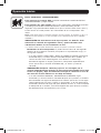
2
Important Safety Instructions
SAVE THESE INSTRUCTIONS
This manual contains important instructions that should be followed during the installation, operation
and storage of all Tripp Lite UPS Systems. Failure to heed these warnings will void your warranty.
UPS Location Warnings
• Use caution when lifting your UPS. Because of the considerable weight of all rackmount UPS
systems, at least two people should assist in lifting and installing them.
• Install your UPS indoors, away from excess moisture or heat, dust or direct sunlight.
• For best performance, the ambient temperature near your UPS should be between 0° C and
40° C (between 32° F and 104° F).
• Leave adequate space around all sides of the UPS for proper ventilation. Do not obstruct its
vents or fan openings.
UPS Connection Warnings
• The UPS contains its own energy source (battery). The output terminals may be live even
when the UPS is not connected to an AC supply.
• Connect your UPS to a properly grounded AC power outlet. Do not modify the UPS’s plug in a
way that would eliminate the UPS’s connection to ground. Do not use adapters that eliminate
the UPS’s connection to ground.
• Do not plug your UPS into itself; this will damage the UPS and void your warranty.
• If you are connecting your UPS to a motor-powered AC generator, the generator must provide
filtered, frequency-regulated, computer-grade output.
Equipment Connection Warnings
• Do not use Tripp Lite UPS Systems for life support applications in which a malfunction or
failure of a Tripp Lite UPS System could cause failure or significantly alter the performance
of a life-support device.
• Do not connect surge suppressors or extension cords to the output of your UPS. This might
overload the UPS and will void the surge suppressor and UPS warranties.
Battery Warnings
• Batteries can present a risk of electrical shock and burn from high short-circuit current. Observe
proper precautions. Do not dispose of the batteries in a fire. Do not open the UPS or batteries.
Do not short or bridge the battery terminals with any object. Unplug and turn off the UPS before
performing battery replacement. Use tools with insulated handles. There are no user-serviceable
parts inside the UPS. Battery replacement should be performed only by authorized service
personnel using the same number and type of batteries (sealed Lead-Acid). The batteries are
recyclable. Refer to your local codes for disposal requirements or in the USA only call
1-800-SAV-LEAD or 1-800-8-BATTERY (1-800-8-228-8379) or visit www.call2recycle.org for
recycling information. Tripp Lite offers a complete line of UPS System Replacement Battery
Cartridges (R.B.C.). Visit Tripp Lite on the Web at www.tripplite.com to locate the specific
replacement battery for your UPS.
• During hot-swap battery replacement, the UPS will not provide backup power in the event of
a blackout or other power interruptions.
• Do not operate UPS without batteries.
• When adding external battery packs to select models with external battery pack connectors,
connect only Tripp Lite-recommended battery packs of the correct voltage and type. Do not
connect or disconnect battery packs when the UPS is operating on battery power.
19-04-288-9332C7.indb 2 4/26/2019 11:13:43 AM

3
Mounting
Mount your equipment in either a 4-post or 2-post rack or rack enclosure. The user must
determine the fitness of hardware and procedures before mounting. If hardware and procedures
are not suitable for your application, contact the manufacturer of your rack or rack enclosure. The
procedures described in this manual are for common rack and rack enclosure types and may not
be appropriate for all applications.
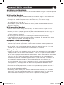
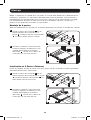
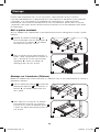
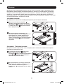
4-Post Rack Mounting
All UPS models include hardware required to mount in a 4-post rack.
1
1
2
2
D
D
A
A
B
B
C
C
1
Attach mounting ears
A
to the front
mounting holes of your equipment
B
using
the screws provided
C
. The ears should
face forward.
2
Using an assistant if necessary, lift your
equipment and mount it to the rack. Attach
it by screwing the appropriate hardware
D
through its mounting ears and into the rack
rails.
2-Post (Telecom) Rack Mounting
Following the procedures below, mount the 1U UPS model in 2-post racks with the included
hardware.
1
Attach mounting ears
A
to the front
mounting holes of your UPS
B
using the
screws provided
C
. The ears should face
backward.
2
Using an assistant if necessary, lift your UPS
and attach it to the rack by passing the
screws, nuts and washers provided
D
through its mounting ears and into the rack
rails.
D
D
19-04-288-9332C7.indb 3 4/26/2019 11:13:45 AM

4
Mounting
Quick Installation
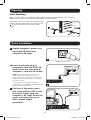
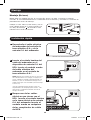
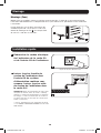
Tower Mounting
Mount all UPS models in an upright, tower position using included hardware. The user must
determine the fitness of hardware and procedures before mounting.
A
A
Stand your UPS on its side with the LED/Control
panel at the top. Attach one rack mounting ear
A
to each side of the UPS using included
screws.
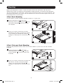
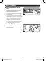
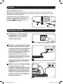
1
Unplug computer’s power cord
from both AC outlet and
computer’s AC input.
2
Insert the female plug of
computer’s cord into UPS’s AC
input. Insert the male plug of
computer’s cord into AC outlet.*
NOTE! after you plug the UPS into a live AC
outlet, the UPS (in “Standby” mode) will
automatically charge its batteries,** but will not
supply power to its outlets until it is turned ON
(see Step 3 below).
* See Specifications for circuit amperage
requirements. ** The BATTERY CHARGE LED will
be the only LED illuminated.
3
Find one of the power cords
that came with the UPS. Insert
the cord’s female plug into
computer’s AC input. Insert the
cord’s male plug into any of
UPS’s female output
receptacles.
IEC320-C14 plug shown
1
2
3
19-04-288-9332C7.indb 4 4/26/2019 11:13:46 AM

5
Quick Installation
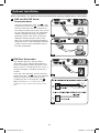
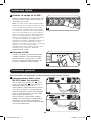
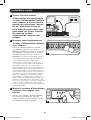
4
5
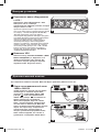
4
Plug your equipment into the
UPS.*
Plug your equipment into the UPS. Repeat
step 3 above using the additional power
cord(s) that came with the UPS.
Note: Additional interconnection cords (C13 to C14)
are available from Tripp Lite. Call 773.869.1234
(Part # P004-006).
* Your UPS is designed to support only computer
equipment. You will overload the UPS if the total VA
ratings for all the equipment you connect exceeds
the UPS’s Output Capacity (see Specifications). To
find your equipment’s VA ratings, look on their
nameplates. If the equipment is listed in amps,
multiply the number of amps by 230 to determine
VA. (Example: 1 amp × 230 = 230 VA). If you are
unsure if you have overloaded the UPS’s outlets,
see “OUTPUT LOAD LEVEL” LED description.
5
Turn the UPS ON.
Press and hold the “ON/OFF/STANDBY”
button for one second. The alarm will beep
once briefly after one second has passed.
Release the button.
19-04-288-9332C7.indb 5 4/26/2019 11:13:46 AM

6
Optional Installation
These connections are optional. Your UPS will function properly without these connections.
4-5
1A
2A
1B
2B
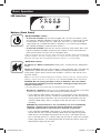
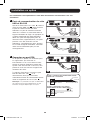
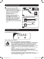
1
USB and RS-232 Serial
Communications
Use the included USB cable (see
1A
) and/
or DB9 serial cable (see
1B
) to connect the
communication port on your computer to
the communication port of your UPS. Install
on your computer the Tripp Lite PowerAlert
Software appropriate to your computer’s
operating system. Your UPS may feature
additional communications ports; these
ports may also be connected to additional
computers which have PowerAlert Software
installed. Consult your PowerAlert manual
for more information.
2
EPO Port Connection
This optional feature is only for those
applications which require connection to a
facility’s Emergency Power Off (EPO) circuit.
When the UPS is connected to this circuit, it
enables emergency shutdown of the UPS’s
inverter.
Using the cable provided, connect the EPO
port of your UPS (see
2A
) to a user-supplied
normally closed or normally open switch
according to the circuit diagram (see
2B
).
Note: The EPO port is not a phone line surge
suppressor; do not connect a phone line to this
port.
19-04-288-9332C7.indb 6 4/26/2019 11:13:47 AM

7
Basic Operation
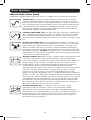
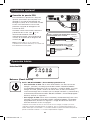
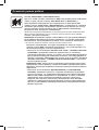
LED Interface
Buttons (Front Panel)
“ON/OFF/STANDBY” Button
• To turn the UPS ON: With the UPS plugged into a live AC wall outlet*, press
and hold the “ON/OFF/STANDBY” button for one second.** Release the button.
If utility power is absent, you can “cold-start” the UPS (i.e.: turn it ON and
supply power for a limited time from its batteries***) by pressing and holding
the “ON/OFF/STANDBY” button for one second.**
• To turn the UPS OFF: With the UPS ON and receiving utility power, press and
hold the “ON/OFF/STANDBY” button for one second.** Then unplug the UPS
from the wall outlet. The UPS will be completely OFF.
* After you plug the UPS into a live AC outlet, the UPS (in “Standby” mode) will automatically
charge its batteries, but will not supply power to its outlets until it is turned ON. ** The alarm
will beep once briefly after the indicated interval has passed. *** If fully charged.
“MUTE/TEST” Button
To Silence (or “Mute”) UPS Alarms: Briefly press and release the “MUTE/TEST”
button.
To Run a Self-Test: With your UPS plugged in and turned ON, press and hold the
“MUTE/TEST” button for two seconds.* Continue holding the button until the
alarm beeps several times and the UPS performs a self-test. See “Results of a
Self-Test” below.
Note: You can leave connected equipment on during a self-test. Your UPS, however, will not
perform a self-test if the UPS is not turned on (see “ON/OFF/STANDBY” Button description).
CAUTION! Do not unplug your UPS to test its batteries. This will remove
safe electrical grounding and may introduce a damaging surge into your
network connections.
* The alarm will beep once briefly after the indicated interval has passed.
Results of a Self-Test: the test will last approximately 10 seconds as the UPS
switches to battery to test its load capacity and battery charge.
• If the “OUTPUT LOAD LEVEL” LED remains lit red and the alarm continues to
sound after the test, the UPS’s outlets are overloaded. To clear the overload,
unplug some of your equipment and run the self-test repeatedly until the
“OUTPUT LOAD LEVEL” LED is no longer lit red and the alarm is no longer
sounding.
CAUTION! Any overload that is not corrected by the user immediately
following a self-test may cause the UPS to shut down and cease
supplying output power in the event of a blackout or brownout.
• If the “BATTERY WARNING” LED remains lit and the alarm continues to
sound after the test, the UPS batteries need to be recharged or replaced.
Allow the UPS to recharge continuously for 12 hours, and repeat the self-
test. If the LED remains lit, contact Tripp Lite for service. If your UPS requires
battery replacement, visit www.tripplite.com to locate the specific Tripp Lite
replacement battery for your UPS.
19-04-288-9332C7.indb 7 4/26/2019 11:13:47 AM

8
Basic Operation
Indicator Lights (Front Panel)
All Indicator Light descriptions apply when the UPS is plugged into a wall outlet and turned ON.
“POWER” LED: This green LED lights continuously when the UPS is ON and
supplying connected equipment with AC power from a utility source. The LED
flashes and an alarm sounds (4 short beeps followed by a pause) to indicate the
UPS is operating from its internal batteries during a blackout or severe brownout.
If the blackout or severe brownout is prolonged, you should save files and shut
down your equipment since internal battery power will eventually be depleted.
See “BATTERY CHARGE” LED description below.
“VOLTAGE CORRECTION” LED: This green LED lights continuously whenever the
UPS is automatically correcting high or low AC voltage on the utility line without
the assistance of battery power. The UPS will also emit a slight clicking noise.
These are normal, automatic operations of the UPS; no action is required on your
part.
“OUTPUT LOAD LEVEL” LED: This multicolored LED indicates the approximate
electrical load of equipment connected to the UPS’s AC outlets. It will turn from
green (light load) to yellow (medium load) to red (overload). If the LED is red
(either illuminated continuously or flashing), clear the overload immediately by
unplugging some of your equipment from the outlets until the LED changes from
red to yellow (or green). CAUTION! Any overload that is not corrected by the user
immediately may cause the UPS to shut down and cease supplying output power
in the event of a blackout or brownout.
“BATTERY CHARGE” LED: When the UPS is operating from utility power, this LED
indicates the approximate charge state of the UPS’s internal batteries: red
indicates the batteries are beginning to charge; yellow indicates the batteries are
roughly midway through charging; and green indicates the batteries are fully
charged. When the UPS is operating from battery power during a blackout or
severe brownout, this LED indicates the approximate amount of energy
(ultimately affecting runtime) which the UPS’s batteries will provide: red indicates
a low level of energy; yellow indicates a medium level of energy; and green
indicates a high level of energy. Since the runtime performance of all UPS
batteries will gradually deplete over time, it is recommended that you periodically
perform a self-test (see “MUTE/TEST” Button description) to determine the energy
level of your UPS batteries BEFORE a blackout or severe brownout occurs. During
a prolonged blackout or severe brownout, you should save files and shut down
your equipment since battery power will eventually be depleted. When the LED
turns red and an alarm sounds continuously, it indicates the UPS’s batteries are
nearly out of power and UPS shut down is imminent.
“BATTERY WARNING” LED: This LED lights red and an alarm sounds
intermittently after you complete a self-test (See “MUTE/TEST” Button
description) to indicate the UPS batteries need to be recharged or replaced.
Allow the UPS to recharge continuously for 12 hours, and repeat the self-test. If
the LED continues to light, contact Tripp Lite for service. If your UPS requires
battery replacement, visit www.tripplite.com to locate the specific Tripp Lite
replacement battery for your UPS.
19-04-288-9332C7.indb 8 4/26/2019 11:13:47 AM

9
Basic Operation
Other UPS Features (Rear Panel)
IEC320-C13/230V
AC Receptacles: Your UPS features IEC320-C13 outlets. These outlets provide
your connected equipment with AC line power during normal operation and
battery power during blackouts and brownouts. The UPS protects equipment
connected to these receptacles against damaging surges and line noise. If you
have a serial or USB connection to your UPS, you can remotely reboot connected
equipment by turning receptacles OFF and ON using Tripp Lite’s PowerAlert
software. Models also feature outlets labeled “UNSWITCHED” which may not be
remotely turned off.
Communications Ports (USB or RS-232): These ports connect your UPS to
any workstation or server. Use with Tripp Lite’s PowerAlert Software and included
cables to enable your computer to automatically save open files and shut down
equipment during a blackout. Also use PowerAlert Software to monitor a wide
variety of AC line power and UPS operating conditions. Consult your PowerAlert
Software manual or contact Tripp Lite Customer Support for more information.
See “USB and RS-232 Serial Communications” in the “Optional Installation”
section for installation instructions.
EPO (Emergency Power Off) Port: Your UPS features an EPO port that may be
used to connect the UPS to a contact closure switch to enable emergency
inverter shutdown. See Optional Installation section.
Accessory Slot: Remove the small cover panel from this slot to install optional
accessories to remotely monitor and control your UPS. Refer to your
accessory’s manual for installation instructions. Contact Tripp Lite at
www.tripplite.com/support for more information, including a list of available
SNMP, network management and connectivity products.
Input Breaker: Protect your electrical circuit from overcurrent draw from the UPS
load. If these breakers trip, remove some of the load; then reset them by
pressing the breaker(s) in.
Output Breaker: Protect your UPS from output overload. If one or more breakers
trip, remove some of the load on the circuit(s), then reset them by pressing the
breaker switch(es) in.
Ground Screw: Use this to connect any equipment that requires a chassis
ground.
19-04-288-9332C7.indb 9 4/26/2019 11:13:47 AM

10
Storage and Service
Battery Replacement
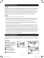
Storage
Before storing your UPS, turn it completely OFF: With the UPS ON and receiving utility power, press
and hold the “ON/OFF/STANDBY” button for one second (an alarm will beep once briefly after the
interval has passed); then, unplug the UPS from the wall outlet. If you store your UPS for an
extended period of time, recharge the UPS batteries once every three months: plug the UPS into a
wall outlet; allow it to charge for 12 hours; and then unplug it and place it back in storage. Note:
after you plug the UPS in, it will automatically begin charging its batteries; however, it will not
supply power to its outlets (see Quick Installation section). If you leave your UPS batteries
discharged for an extended period of time, they will suffer a permanent loss of capacity.
Service
Before returning your UPS for service, follow these steps:
1. Review the installation and operation instructions in this manual to ensure that the service
problem does not originate from a misreading of the instructions. Also, check that the UPS
System’s circuit breaker(s) are not tripped. This is the most common cause of service inquiries
which can be easily remedied by following the resetting instructions in this manual.
2. If the problem continues, do not contact or return the UPS to the dealer. Instead, contact
Tripp Lite at www.tripplite.com/support. A service technician will ask for the UPS’s model
number, serial number and purchase date.
3. If the problem requires service, the technician will issue you a Returned Material Authorization
(RMA) number, which is required for service. If you require packaging, the technician can
arrange to send you proper packaging. Securely pack the UPS to avoid damage during shipping.
Do not use Styrofoam beads for packaging. Any damages (direct, indirect, special, incidental or
consequential) to the UPS incurred during shipment to Tripp Lite or an authorized Tripp Lite
service center is not covered under warranty. UPS Systems shipped to Tripp Lite or an authorized
Tripp Lite service center must have transportation charges prepaid. Mark the RMA number on
the outside of the package. If the UPS System is within the 2-year warranty period, enclose a
copy of your sales receipt. Return the UPS for service using an insured carrier to the address
given to you by the Tripp Lite service technician.
Under normal conditions, the original batteries in your UPS will last many years. See Safety section
before replacing batteries. The batteries are designed for hot-swap replacement (i.e. leaving the
UPS in ON mode), but qualified service personnel may wish to put the UPS in the OFF mode before
proceeding.
1/6
2/5
3/4
Procedure
1
Remove Front Panel
2
Disconnect Batteries
3
Remove/Dispose of
Batteries
4
Add Batteries
5
Connect Batteries
Attach connectors: black-to-
black and red-to-red.
6
Replace Front Panel
19-04-288-9332C7.indb 10 4/26/2019 11:13:47 AM

11
1111 W. 35th Street, Chicago, IL 60609 USA • www.tripplite.com/support
FCC RADIO/TV INTERFERENCE NOTICE: (FOR CLASS A MODELS)
Note: This equipment has been tested and found to comply with the limits for a Class A digital device, pursuant to Part 15 of the
FCC Rules. These limits are designed to provide reasonable protection against harmful interference when operated in a commercial
environment. This equipment generates, uses and can radiate radio frequency energy, and if not installed and used in accordance
with the instruction manual, may cause interference to radio communications. Operation of this equipment is likely to cause
harmful interference in which case the user will be required to correct the interference at his own expense. The user must use
shielded cables and connectors with this product. Any changes or modifications to this product not expressly approved by the party
responsible for compliance could void the user’s authority to operate the equipment.
FCC RADIO/TV INTERFERENCE NOTICE: (FOR CLASS B MODELS)
Note: This equipment has been tested and found to comply with the limits for a Class B digital device, pursuant to Part 15 of the
FCC Rules. These limits are designed to provide reasonable protection against harmful interference in a residential installation. This
equipment generates, uses and can radiate radio frequency energy, and if not installed and used in accordance with the instruction
manual, may cause interference to radio communications. However, there is no guarantee that interference will not occur in a
particular installation. If this equipment does cause harmful interference to radio or television reception, which can be determined
by turning the equipment off and on, the user is encouraged to try to correct the interference using one or more of the following
measures: reorient or relocate the receiving antenna; increase the separation between the equipment and the receiver; connect the
equipment into an outlet on a circuit different from that which the receiver is connected; consult the dealer or an experienced radio/
television technician for help. The user must use shielded cables and connectors with this product. Any changes or modifications to
this product not expressly approved by the party responsible for compliance could void the user’s authority to operate the
equipment. This device complies with part 15 of the FCC rules. Operation is subject to the following 2 conditions: (1) This device
may not cause harmful interference, and (2) This device must accept any interference received, including interference that may
cause undesired operation.
Regulatory Compliance Identification Numbers
For the purpose of regulatory compliance certifications and identification, your Tripp Lite product has been assigned a unique series
number. The series number can be found on the product nameplate label, along with all required approval markings and
information. When requesting compliance information for this product, always refer to the series number. The series number should
not be confused with the marketing name or model number of the product.
Tripp Lite has a policy of continuous improvement. Product specifications are subject to change without notice.
Note on Labeling
Two symbols are used on the label.
V~ : AC Voltage
V : DC Voltage
Product Registration
Visit www.tripplite.com/warranty today to register your new Tripp Lite product. You’ll be automatically entered into
a drawing for a chance to win a FREE Tripp Lite product!*
* No purchase necessary. Void where prohibited. Some restrictions apply. See Web site for details.
19-04-288 93-32C7_revC
19-04-288-9332C7.indb 11 4/26/2019 11:13:48 AM

12
Manual del propietario
SmartPro
®
1U Rackmount
Sistemas de UPS Inteligentes e Interactivos en Línea
SMX500RT1U
Serie: AG-0098
Instrucciones de seguridad importantes 13
Montaje 14
Instalación rápida 15
Instalación opcional 16
Operación básica 17
Almacenamiento y servicio 21
Reemplazo de batería 22
English 1
Français 23
Póññêèé 34
1111 W. 35th Street, Chicago, IL 60609 USA • www.tripplite.com/support
Copyright ©2019 Tripp Lite. Todos los derechos reservados.
SmartPro
®
es una marca comercial registrada de Tripp Lite.
19-04-288-9332C7.indb 12 4/26/2019 11:13:48 AM

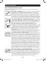
13
Instrucciones de seguridad importantes
GUARDE ESTAS INSTRUCCIONES
Este manual contiene importantes instrucciones que deben seguirse durante la instalación,
operación y el almacenamiento de todos los UPS de Tripp Lite. La no observancia de estas
advertencias anulará su garantía.
Advertencias sobre la ubicación del UPS
• Tenga cuidado al levantar el UPS. Debido al gran peso de los UPS para montaje en bastidor,
se requieren por lo menos dos personas para que le ayuden a levantarlos e instalarlos.
• Instale su UPS bajo techo, lejos de la humedad, el calor, el polvo o la luz solar directa.
• Para un mejor funcionamiento, la temperatura ambiente cerca de su UPS debe estar entre 0° C
y 40° C (32° F - 104° F)
• Deje una cantidad adecuada de espacio alrededor de todos los lados del UPS para sua
adecuada ventilación. No obstruya sus respiraderos ni las aberturas de ventilación.
Advertencias sobre la conexión del UPS
• El UPS contiene su propia fuente de energía (batería). Los terminales de salida pueden estar
con energía incluso cuando el UPS no está conectado a un suministro de corriente alterna.
• Conecte su UPS a una toma de CA puesta a tierra apropiadamente. No modifique el enchufe
del UPS en ninguna forma que elimine su conexión a tierra. No use adaptadores que eliminen la
conexión del UPS a tierra.
• No conecte el UPS a si mismo ya que podría dañarse y anular la garantía.
• Si va a conectar su UPS a un generador de corriente alterna accionado por un motor, el
generador debe suministrar una salida filtrada, con regulación por frecuencia grado computadora.
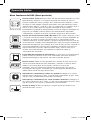
Advertencias sobre la conexión de equipos
• No utilice sistemas UPS de Tripp Lite para aplicaciones de soporte de vida en las que un
funcionamiento defectuoso o una falla del UPS pudiera causar un mal funcionamiento o una
alteración importante en el funcionamiento de un dispositivo de soporte de vida.
• No conecte supresores de sobretensiones ni cordones de extensión a la salida de su UPS. Esto
puede sobrecargarlo y anular su garantía y la del supresor de sobretensiones.
Advertencias sobre la batería
• Las baterías presentan un peligro de choque eléctrico y quemaduras debido a las altas
corrientes de cortocircuito. Observe las precauciones apropiadas. No deseche las baterías en un
incinerador. No abra el UPS ni las baterías. No ponga los terminales de la batería en corto o en
puente con ningún objeto. Apague y desconecte el UPS antes de reemplazar la batería. Use
herramientas con mangos aislados. No hay piezas que el usuario pueda reparar dentro del UPS.
El reemplazo de baterías debe ser realizado solamente por personal de servicio autorizado
usando el mismo número y tipo de baterías (plomo-ácido, selladas). Las baterías son
reciclables. Consulte la reglamentación local para los requisitos de disposición de desechos; en
los EE.UU. llame al 1-800-SAV-LEAD o al 1-800-8-BATTERY (1-800-8-228-8379) o visite
www.call2recycle.org para obtener información sobre el proceso de reciclaje. Tripp Lite ofrece
una línea completa de cartuchos de reemplazo de batería para UPS (R.B.C.) Visite la página
web de Tripp Lite en www.tripplite.com para localizar la batería de reemplazo específica para su
UPS.
• Durante el reemplazo de baterías en operación (hot-swap), el UPS no proporcionará energía de
respaldo en el caso de una falla del servicio eléctrico u otras interrupciones de energía.
• No opere el UPS sin baterías.
• Al agregar bancos de baterías externas a modelos exclusivos con conectores para este tipo de
bancos, sólo emplee bancos recomendados por Tripp Lite del voltaje y tipo correctos. No
conecte ni desconecte bancos de baterías cuando el UPS esté funcionando con energía de las
baterías.
19-04-288-9332C7.indb 13 4/26/2019 11:13:48 AM

14
Montaje
Monte su equipo en un bastidor de 2 o 4 postes. El usuario debe determinar la idoneidad de los
materiales y accesorios, así como de los procedimientos antes del montaje. Si los materiales y
procedimientos no son adecuados para su aplicación, contacte con el fabricante de su bastidor.
Los procedimientos descritos en este manual son para bastidores comunes y de tipo caja y
podrían no ser apropiados para todas las aplicaciones.
Montaje de 4 postes
Todos los modelos de UPS incluyen los accesorios requeridos para montar un bastidor de 4 postes.
1
1
2
2
D
D
A
A
B
B
C
C
1
Instale las orejas de instalación
A
en los
orificios frontales de instalación de su
equipo
B
usando los tornillos suministrados
C
. Las orejas deben apuntar al frente.
2
Usando un ayudante si fuera necesario,
levante su equipo e instálelo en el rack.
Sujételo atornillando los accesorios
adecuados
D
a través de sus orejas de
instalación y en los rieles del rack.
Instalación en 2 Postes (Telecom)
Instale los modelos de UPS de 1U en racks de 2 postes con los accesorios incluidos siguiendo el
procedimiento descrito a continuación.
1
Instale las orejas de instalación
A
en los
orificios frontales de instalación de su equipo
B
usando los tornillos suministrados
C
. Las
orejas deben apuntar hacia atrás.
2
Usando un ayudante si fuera necesario,
levante su equipo e instálelo en el rack.
Sujételo atornillando los accesorios
adecuados
D
a través de sus orejas de
instalación y en los rieles del rack.
D
D
19-04-288-9332C7.indb 14 4/26/2019 11:13:50 AM

15
Montaje
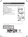
Instalación rápida
Montaje (En torre)
Monte todos los modelos de UPS en una posición vertical, de torre, usando los accesorios
incluidos. El usuario debe determinar la idoneidad de los materiales y accesorios así como de los
procedimientos antes del montaje.
A
A
Coloque su UPS sobre la parte lateral y con el
panel LED/de control en la parte superior. Fije
una oreja de montaje
A
del bastidor a cada
lado del UPS usando los tornillos.
1
Desenchufe el cable eléctrico
del ordenador del enchufe de
toma eléctrica C.A. y de la
entrada C.A. del ordenador.
2
Inserte el enchufe hembra del
cable del ordenador en el
dispositivo de entrada C.A. del
UPS. Inserte el enchufe macho
del cable eléctrico del
ordenador en el enchufe de
toma eléctrica C.A.*
NOTA Después de conectar el UPS en una toma
de corriente alterna con energía, el equipo (en
modo “Standby”) cargará automáticamente sus
baterías,** pero no suministrará energía a sus
salidas hasta que sea encendido (vea más abajo
el Paso 15)
*Vea las especificaciones técnicas sobre los
requerimientos de amperaje para circuito. **El
único diodo o indicador iluminado será el de
recargo de batería.
3
Busque uno de los cables
eléctricos que vienen con el
UPS. Inserte el enchufe hembra
en la toma eléctrica de entrada
C.A. del ordenador. Inserte el
enchufe macho en cualquiera
de los receptáculos de salida
del UPS.
IEC320-C14 enchufe demostrado
1
2
3
19-04-288-9332C7.indb 15 4/26/2019 11:13:51 AM

16
Instalación rápida
4
5
4
Enchufe su equipo en el UPS.*
Repita el procedimiento 3 mencionado arriba
usando los demás cables eléctricos que se
adjuntaron con el UPS.
Nota: Se pueden obtener cables de interconexión
adicionales (C13 a C14) través de Tripp Lite. Llame
al +1.773.869.1234 (Repuesto # P004-006).
*Su UPS ha sido diseñado para apoyar su equipo
de ordenadores solamente. Usted sobrecargará el
UPS si el total del índice de los voltios/ amperios
para todo el equipo excede la capacidad de salida
del UPS (ver especificaciones). Para averiguar el
índice de voltios/amperios de su equipo, búsquelos
en la placa del fabricante.Si el equipo está
enumerado en amperios, multiplique el número de
amperios por 230 para determinar los voltios/
amperios (Por ejemplo: 1 amp x 230 = 230 voltios/
amperios). Si no está seguro de haber
sobrecargado las tomas eléctricas del UPS, vea la
descripción sobre el indicador “NIVEL DE
SOBRECARGA DE SALIDA”.
5
Encienda el UPS.
Presione y mantenga presionado el botón
“ON/OFF/STANDBY” (Encendido/Apagado/
Reserva) durante un segundo. La alarma
emitirá un pitido brevemente después de
pasado un segundo. Suelte el botón.
Instalación opcional
Estas conexiones son opcionales. Su UPS funcionará correctamente sin ellas.
1A
1B
1
Comunicaciones USB y serie
RS-232 (todos los modelos)
Use el cable USB incluido (vea
1A
) y/o el
cable serie DB9 (vea
1B
) para conectar el
puerto de comunicaciones de su
computadora al puerto de comunicaciones
de su UPS. Instale en su computadora el
software PowerAlert de Tripp Lite apropiado
para su sistema operativo. Su UPS puede
tener puertos adicionales de
comunicaciones; estos puertos también
pueden estar conectados a computadoras
adicionales con el software PowerAlert
instalado. Consulte su manual de PowerAlert
para mayor información.
19-04-288-9332C7.indb 16 4/26/2019 11:13:51 AM

17
Operación básica
4-5
OPCIÓN 1: INTERRUPTOR NORMALMENTE CERRADO
PROPORCIONADO POR EL USUARIO
OPCIÓN 2: PROPORCIONADO POR EL USUARIO
NORMALMENTE ABIERTO DEL INTERRUPTOR
INTERRUPTOR
EPO
INTERRUPTOR EPO
SALTADOR
SIN CONEXIÓN
SIN CONEXIÓN
2A
2B
Interfaz LED
Botones (Panel frontal)
Botón “ON/OFF/STANDBY” (Encendido/Apagado/Reserva)
• Para encender el UPS: Con el UPS conectado en una toma de CA con
energía*, presione y mantenga presionado el botón “ON/OFF/STANDBY”
(Encendido/Apagado/Reserva) por un segundo.** Suelte el botón. Si no hay
energía de la red, puede “arrancar en frío”el UPS (es decir, encenderlo y
suministrar energía de sus baterías por un tiempo limitado***) presionando y
manteniendo presionado el botón “ON/OFF/STANDBY” (Encendido/Apagado/
Reserva) durante un segundo.**
• Para apagar el UPS: Con el UPS encendido y recibiendo energía de la red,
presione y mantenga presionado el botón “ON/OFF/STANDBY” (Encendido/
Apagado/Reserva) durante un segundo.** Luego desconecte el UPS de la
toma de corriente. El UPS se apagará.
* Después de conectar el UPS en una toma de CA con energía, el equipo (en modo
“Standby”) cargará automáticamente sus baterías, pero no suministrará energía a sus
salidas hasta que sea encendido. ** La alarma emitirá un pitido brevemente después de
pasado el intervalo indicado. *** Si está completamente cargada..
2
Conexión de puerto EPO
Esta característica opcional es sólo para
aquellas aplicaciones que requieran una
conexión al circuito de desconexión de
emergencia (EPO) de la instalación Cuando
el UPS está conectado a este circuito,
permite el apagado de emergencia del
inversor del UPS.
Usando el cable suministrado, conecte el
puerto EPO de su UPS (vea
2A
) a un
contacto normalmente cerrado o
normalmente abierto suministrado por el
usuario, de acuerdo con el diagrama del
circuito (vea
2B
).
Nota: El puerto EPO no es un supresor de
sobretensiones de línea telefónica; no conecte una
línea telefónica en este puerto.
Instalación opcional
19-04-288-9332C7.indb 17 4/26/2019 11:13:52 AM

18
Operación básica
Botón “MUTE/TEST” (SILENCIO/PRUEBA)
Para silenciar las alarmas UPS: Presione brevemente el botón MUTE/TEST
(SILENCIO/PRUEBA) y luego suéltelo.
Para ejecutar una auto-prueba: Con su UPS conectado y encendido, presione
y mantenga presionado el botón MUTE/TEST (Silencio/Prueba) por dos
segundos.*Siga presionando el botón hasta que la alarma suene varias veces y
el UPS realice una auto-prueba. Vea “Resultados de una auto-prueba” más
abajo.
Nota: Puede dejar equipos conectados durante una auto-prueba. Sin embargo, el UPS, no
realizará una auto-prueba si no está encendido (vea la descripción del Botón “ON/OFF/
STANDBY”).
¡PRECAUCIÓN! No desconecte su UPS para probar sus baterías. Esto
eliminaría la conexión de seguridad a tierra y podría introducir una
sobretensión dañina en sus conexiones de red.
* La alarma emitirá un pitido brevemente después de pasado el intervalo indicado.
Resultados de una auto-prueba: La prueba durará cerca de 10 segundos
mientras el UPS conmuta a batería para probar su capacidad de carga y la
recarga de la batería.
• Si el LED “OUTPUT LOAD LEVEL” (NIVEL DE CARGA DE SALIDA) permanece
encendido rojo y la alarma continúa sonando después de la prueba, las
salidas del UPS están sobrecargadas. Para eliminar la sobrecarga,
desconecte algo de su equipo y ejecute la auto-prueba repetidamente
hasta que el LED ya no esté encendido rojo y la alarma ya no esté
sonando.
¡PRECAUCIÓN! Cualquier sobrecarga que no sea corregida por el
usuario inmediatamente después de una auto-prueba puede causar que
el UPS se apague y deje de suministrar energía de salida en el caso de
una falla del servicio eléctrico o una baja de voltaje.
• Si el LED “BATTERY WARNING” (ADVERTENCIA DE BATERÍA) sigue
encendido y la alarma continúa sonando después de la prueba, las baterías
del UPS deben recargarse o reemplazarse. Permita que el UPS se recargue
continuamente por 12 horas y repita la auto-prueba. Si el LED permanece
encendido, contacte con Tripp Lite para obtener servicio. Si su UPS requiere
el reemplazo de su batería, visite www.tripplite.com para localizar la batería
de reemplazo Tripp Lite específica para su UPS.
19-04-288-9332C7.indb 18 4/26/2019 11:13:52 AM

19
Operación básica
Luces indicadoras (Panel frontal)
Todas las descripciones de luces indicadoras se aplican cuando el UPS está conectado en un
tomacorriente y encendido.
LED “POWER” (ALIMENTACIÓN): Este LED verde se enciende permanentemente
cuando el UPS está encendido y proporcionando energía de CA al equipo
conectado desde el suministro de red. El LED destella y una alarma suena (4
pitidos cortos seguidos de una pausa) para indicar que el UPS está operando
con sus baterías internas durante una falla del servicio eléctrico o una severa
baja de voltaje. Si la falla o la baja de voltaje es muy prolongada, debe guardar
sus archivos y apagar su equipo ya que la energía de la batería interna finalmente
se agotará. Vea la descripción del LED “BATTERY CHARGE” (CARGA DE BATERÍA)
LED “VOLTAGE CORRECTION” (CORRECCIÓN DE VOLTAJE): Este LED verde se
enciende en forma permanente cuando el UPS está corrigiendo automáticamente
el voltaje de CA alto o bajo en la línea de la red sin la ayuda de energía de
baterías. El UPS también emitirá un ligero clic. Estas son operaciones normales y
automáticas del UPS y no requieren de ninguna acción de su parte.
LED “OUTPUT LOAD LEVEL” (NIVEL DE CARGA DE SALIDA): Este LED
multicolor indica la carga eléctrica aproximada del equipo conectado a las salidas
de CA del UPS. Se encenderá desde verde (carga ligera) a amarillo (carga media)
y a rojo (sobrecarga) Si el LED está rojo (ya sea iluminado permanentemente o
destellando), elimine la sobrecarga de inmediato desconectando algo de su
equipo de las salidas hasta que el LED cambie de rojo a amarillo (o verde).
¡PRECAUCIÓN! Cualquier sobrecarga que no sea corregida por el usuario
inmediatamente puede causar que el UPS se apague y deje de suministrar energía
de salida en el caso de un falla del servicio eléctrico o una baja de voltaje.
LED “BATTERY CHARGE” (CARGA DE BATERÍA): Cuando el UPS opera con la
energía de la red, este LED indica el estado aproximado de carga de las baterías
internas del UPS; el rojo indica que las baterías están comenzando a cargarse; el
amarillo indica que las baterías están aproximadamente a media recarga; y el
verde indica que las baterías están totalmente cargadas. Cuando el UPS opera
con energía de las baterías durante una falla del servicio eléctrico o una baja de
voltaje severa, este LED indica la cantidad aproximada de energía (que a fin de
cuentas afecta el tiempo de respaldo) que proporcionarán las baterías del UPS;
el rojo indica un bajo nivel de energía, el amarillo un nivel mediano y el verde un
nivel alto de energía. Ya que el rendimiento del tiempo de respaldo de todas las
baterías del UPS se reducirá gradualmente, se recomienda realizar una auto-
prueba periódicamente (vea la descripción del botón “MUTE/TEST” (SILENCIO/
PRUEBA)) para determinar el nivel de energía de las baterías de su UPS ANTES
de que ocurra una falla del servicio eléctrico o una baja de voltaje severa. Durante
una falla prolongada o una severa baja de voltaje, debe guardar sus archivos y
apagar su equipo ya que la energía de baterías se agotará finalmente. Cuando el
LED se enciende rojo y una alarma suena en forma continua, indica que las
baterías del UPS están casi sin energía y es inminente que el UPS se apague.
LED “BATTERY WARNING” (ADVERTENCIA DE BATERÍA): Este LED se enciende
rojo y una alarma suena en forma intermitente después de iniciar una auto-
prueba (vea la descripción del botón “MUTE/TEST” (SILENCIO/PRUEBA)) para
indicar que las baterías del UPS deben ser recargadas o reemplazadas. Permita
que el UPS se recargue continuamente por 12 horas y repita la auto-prueba. Si
el LED sigue encendido, contacte con Tripp Lite para que le brinden servicio. Si
su UPS requiere el reemplazo de su batería, visite www.tripplite.com para
localizar la batería de reemplazo Tripp Lite específica para su UPS.
19-04-288-9332C7.indb 19 4/26/2019 11:13:52 AM

20
Operación básica
Otras funciones del UPS (Panel posterior)
IEC320-C13/230V
Tomacorrientes de CA: Su UPS cuenta con tomacorrientes IEC320-C13. Estos
tomacorrientes alimentan a su equipo conectado con energía de línea CA
durante la operación normal y energía de la batería durante apagones y caídas
de voltaje. El UPS protege al equipo conectado a estos tomacorrientes contra
sobretensiones dañinas y ruido en la línea. Si usted tiene una conexión serial o
USB a su UPS, puede reiniciar el equipo conectado en forma remota
encendiendo y apagando los tomacorrientes usando el Programa PowerAlert de
Tripp Lite. Los modelos cuentan además con tomacorrientes etiquetados
“UNSWITCHED” [Siempre Vivo], que no pueden apagarse en forma remota.
Puertos de comunicaciones (USB o RS-232): Estos puertos conectan su UPS
a cualquier estación de trabajo o servidor. Úselos con el software PowerAlert de
Tripp Lite y los cables incluidos para permitir que su computadora guarde
automáticamente los archivos abiertos y apague el equipo durante una falla del
servicio eléctrico. También utilice PowerAlert para vigilar una amplia variedad de
condiciones de operación de la energía de la línea de CA y del UPS. Consulte su
manual de PowerAlert o contacte con el Soporte al cliente de Tripp Lite para
mayor información. Consulte “Comunicaciones USB y serie RS-232” en la
sección “Instalación opcional” para obtener la información sobre las
instrucciones de instalación.
Puerto EPO (Desconexión de emergencia): Su UPS tiene un puerto EPO que
puede usarse para conectar el UPS a un contacto de cierre para permitir el
apagado de emergencia del inversor. Consulte Instalación opcional.
Ranura auxiliar: Retire el panel pequeño de la cubierta de esta ranura para
instalar accesorios opcionales para monitorear y controlar su UPS en forma
remota. Para instrucciones de instalación, consulte su manual de
accesorios. Para más información póngase en contacto con Tripp Lite en
www.tripplite.com/support, incluyendo una lista de productos disponibles de
SNMP, administración de red y conectividad.
Interruptor(es) automático(s) (todos los modelos): Protege(n) su circuito
eléctrico contra sobrecarga al UPS. Si uno de estos interruptores dispara, retire
algo de carga y restablézcalo presionando el interruptor.
Interruptor(es) automático(s) de salida (modelos exclusivos): Protege(n) su
UPS contra sobrecargas en la salida.. Si uno o más interruptores disparan, retire
algo de carga de sus circuitos y restablézcalos presionándolos.
Tornillo de tierra: Úselo para conectar cualquier equipo que requiera una
conexión de tierra a chasis.
19-04-288-9332C7.indb 20 4/26/2019 11:13:52 AM
La pagina si sta caricando...
La pagina si sta caricando...
La pagina si sta caricando...
La pagina si sta caricando...
La pagina si sta caricando...
La pagina si sta caricando...
La pagina si sta caricando...
La pagina si sta caricando...
La pagina si sta caricando...
La pagina si sta caricando...
La pagina si sta caricando...
La pagina si sta caricando...
La pagina si sta caricando...
La pagina si sta caricando...
La pagina si sta caricando...
La pagina si sta caricando...
La pagina si sta caricando...
La pagina si sta caricando...
La pagina si sta caricando...
La pagina si sta caricando...
La pagina si sta caricando...
La pagina si sta caricando...
La pagina si sta caricando...
La pagina si sta caricando...
-
 1
1
-
 2
2
-
 3
3
-
 4
4
-
 5
5
-
 6
6
-
 7
7
-
 8
8
-
 9
9
-
 10
10
-
 11
11
-
 12
12
-
 13
13
-
 14
14
-
 15
15
-
 16
16
-
 17
17
-
 18
18
-
 19
19
-
 20
20
-
 21
21
-
 22
22
-
 23
23
-
 24
24
-
 25
25
-
 26
26
-
 27
27
-
 28
28
-
 29
29
-
 30
30
-
 31
31
-
 32
32
-
 33
33
-
 34
34
-
 35
35
-
 36
36
-
 37
37
-
 38
38
-
 39
39
-
 40
40
-
 41
41
-
 42
42
-
 43
43
-
 44
44


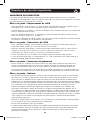
Tripp Lite SMX500RT1U UPS Manuale del proprietario
- Categoria
- Gruppi di continuità (UPS)
- Tipo
- Manuale del proprietario
in altre lingue
Documenti correlati
-
Tripp Lite SmartOnline 220/230/240V Input/Output Manuale del proprietario
-
Tripp Lite SmartOnline SU6000RT3U Manuale del proprietario
-
-
-
-
-
-
Tripp Lite TLP82NSATF Manuale del proprietario
-