
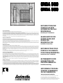
MOTORIDUTTORE PER
CANCELLI AD ANTE
SCORREVOLI PER USO
RESIDENZIALE
Istruzioni per l’installazione
GEARED-MOTOR FOR
SLIDING GATES AND
DOORS FOR
RESIDENTIAL USE
Installation Instructions
MOTOREDUCTEUR POUR
PORTAILS COULISSANTS
POUR USAGE RESIDENTIEL
Instructions pour l’installation
GETRIEBEMOTOR FÜR
SCHIEBETORE FÜR
PRIVATEN GEBRAUCH
Installationsanleitung
MOTORREDUCTOR PARA
PUERTAS CORREDERAS
DE USO RESIDENCIAL
Instrucciones de instalación
PER UN CORRETTO MONTAGGIO LEGGERE ATTENTAMENTE LE ISTRUZIONI.
FOR A CORRECT ASSEMBLY, CAREFULLY READ THE FOLLOWING.
POUR UN ASSEMBLAGE CORRECT, LIRE ATTENTIVEMENT LES ISTRUCTIONS.
FÜR EINE KORREKTE INSTALLATION, DIESE ANLEITUNGEN SORGFÄLTING LESEN.
LEER ATENTAMENTE LAS INSTRUCCIONES PARA UN MONTAJE CORRECTO.
Scopo del manuale
Questo manuale è stato redatto dal costruttore ed è parte integrante del prodotto.
Le informazioni sono dirette agli operatori esperti che eseguono l’installazione e la manutenzione straordinaria. Essi devono possedere competenze specifiche
e particolari capacità per eseguire correttamente ed in sicurezza gli interventi di loro competenza.
La costante osservanza delle informazioni garantisce la sicurezza dell’uomo, l’economia di esercizio ed una più lunga durata di funzionamento del prodotto.
Al fine di evitare manovre errate con il rischio di incidenti, è importante leggere attentamente questo manuale, rispettando scrupolosamente le informazioni fornite.
Considerando che tale prodotto va installato in abitazioni residenziali, l’operatore esperto, dopo aver effettuato l’intervento dovrà constatarne la corretta
installazione ed il regolare funzionamento. Succcessivamente dovrà istruire l’utente sull’uso corretto del prodotto rilasciando tutta la documentazione prevista
del costruttore.
L’indice descrittivo, posto all’inizio, consente facilmente la rintracciabilità degli argomenti di interesse.
Purpose of the manual
This manual has been prepared by the manufacturer and is an integral part of the product.
The information is aimed at expert installers and those carrying out extraordinary maintenance operations.
These persons must be specifically qulified to carry out this work correctly and under the maximum safety conditions.
Scrupulous observance of the instructions will ensure safety for man, economic running and a long product functioning life. To avoid incorrect manoeuvres and
therefore the risk of accidents, it is essential to read this manual with care and strictly follow all the instructions given.
As this is a product to be installed in residential buildings, the expert installer, after completing installation must verify that this has been performed correctly and
that the product functions smoothly. Subsequently, it is necessary to instruct the user on the correct use of the product providing all the documentation envisaged
by the manufacturer.
Objectif de la notice
Ce manual a été rédigé par le fabricant et fait partie intégrante du produit.
Les informations qui y sont contenues s’adressent aux opérateurs spécialisés qui effectuent les opérations de pose et d’entretien extraordinaire. Ceux-ci doivent
posséder des compétences et des qulités spécifiques pour effectuer de façon correcte et en toute sécurité les interventions relevant de leur compétence directe.
La constante observation de ces informations garantit la sécurité des personnes, une économie d’utilisation et une plus longue durée de fonctionnement du
produit.
Lire attentivement ce manual et en respecter scrupuleusement les informations pour éviter toute fausse manoeuvre qui pourrait entratener des accidents.
Ce produit doit être posé dans des habitations résidentielles. Après en avoir effectué la pose, l’opérateur devra en vérifier la bonne installation et le bon
fonctionnement.
Il devra ensuite informer l’utilisateur sur la bonne utilisation du produit et lui remettre toute la documentation prévue par le fabricant.
Le sommaire détaillé, placé au début du manuel, permet de retrouver facilement les sujets à consulter.
Zweck der montageanleitung
LEITUNG
Das vorliegende Handbuch wurde vom Hersteller vertaßt und ist Bestandteil des Produkts.
Die darin enthaltenen informationen richten sich an erlahrenes Personal, das sowohl die installation als auch außerordentliche Wartungsarbeiten durchführt.
Dieses Personal muß über spezifische Fähigkeiten und Kompetenzen verfügen, um die Arbeit korrekt und unter sicheren Bedingungen durchfüren zu konnen.
Die ständige Beachtung der Anweisungen gewährleistet Sicherheit, wirtschaftlichen Betrieb der Anlage und eine längere Lebensdaurer des Produkts. Zur
Vermeidung von Fehlern, die zu Unfällen führen könnten, muß das vortiegene Handbuch aufmerksam durchgelesen und die darin enthaltenen Anweisungen
genau befolgt werden.
Da das Produkt im Privatwohnbereich installier wird, muß das erfahrene Personal nach der installation die korrekte Montage und den einwandfreien Betrieb
überprüfen. Anschließend muß es den Benutzer in den richtigen Gebrauch des Produkts einweisen und ihm die vom Hersteller vorgesehene Dokumentation
aushändigen.
Das Inhaltsverzeichnis am Anfang des Handbuchs ermöglicht eine schnelle Ermittlung der jeweiligen Punkte.
Objetivo del manual
Este manual ha sido redactado por el constructor y forma para integrante del producto. Las informaciones que contiene van dirigidas a los operadores
especializados encargados de las operaciones de installación y mantenimiento extraordinario. Dichos operadores deberán poseer la competencia especifica
y las capacidades necesarias para llevar a efecto correctamente y en condiciones de seguridad las operaciones de las que están encargados. El cumplimiento
constante de estas instrucciones garantiza seguridad del personal, economia de uso y un funcionamiento más duradero del producto.
A fin de evitar maniobras incorrectas con el consiguiente riesgo de accidentes cabe leer con atención este manual y respetar escrupulosamente las instrucciones
proporcionadas. Puesto que el producto está destinado a la instalación en viviendas, el operador especializado, después de realizar la instalación, tendrá que
comprobar la correcta ejecución de la misma y el buen funcionamiento del producto. Luego tendrá que ense-ar al cliente la forma correcta de utilización del
producto, entregando toda la documentación facilitada por el constructor. El índice descriptivo inicial permite encontrar con facilidad los temas que interesen.
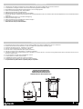
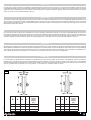
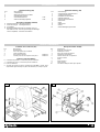
ONDA 500ONDA 500
ONDA 500ONDA 500
ONDA 500
R
L' APERTURA AUTOMATICA
COD.67954-0024700 3/99
AP005 P1AP005 P1AP005
P1AP005 P1
ONDA 800ONDA 800
ONDA 800ONDA 800
ONDA 800

2
AP006 P2
Dati tecnici
Technical data
Donnees,techniques
Technische daten
Datos tecnicos...........................................................................................................................................................................................................................5
Caratteristiche generali
Caracteristiques generales
Allgemeine merkmale
Caracteristicas generales
Caratteristiche generali ............................................................................................................................................................................................................6
Controlli preliminari
Preliminary checks
Controles preliminaires
Vorkontrollen
Controles preliminares .............................................................................................................................................................................................................8
Guide inferiori
Lower guides
Guides inferieurs
Untere laufbahnen
Guias inferiores......................................................................................................................................................................................................................... 9
Guide superiori
Upper guides
Guides superieurs
Obere laufbahnen
Guias superiores...................................................................................................................................................................................................................... 10
Ruote
Wheels
Roues
Rader
Ruedas.................................................................................................................................................................................................................................... 11
Disposizione dei componenti
Arrangement of the components
Distribution des elements composant le motoreducteur
Anordnung der bauteile
Colocacion de los componentes ............................................................................................................................................................................................12
Verifica scelta automazione
Assessing automation selected
Verification du choix de l’automatisation
Wahl der automation
Comprobacion de la eleccion de la automatizacion...............................................................................................................................................................14
Dispositivi antischiacciamento (raccomandazioni ed avvertenze)
Devices to prevent squashing (advice and warnings)
Dispositifs anti-ecrasement (recommandations et remarques)
Einklemmschutzvorrichtungen (empfehlungen und hinweise)
Dispositivos antiaplastamiento (recomendaciones y advertencias)....................................................................................................................................... 16
Verifica componenti motoriduttore ONDA 500/ONDA 800
Checking components of geared-motor ONDA 500/ONDA 800
Verification des pieces composant le motoreducteur ONDA 500/ONDA 800
Kontrolle der getriebemotor-bauteile ONDA 500/ONDA 800
Comprobacion de los componentes del motorreductor ONDA 500/ONDA 800 .................................................................................................................... 17
INDICE /
CONTENTS
/ TABLE DES MATIERES /
INHALTSVERZEICHNIS
/ INDICE
B
A

3
AP006 P3
Installazione dell’ automazione (modalità - ingombri)
Installation of automatic control unit (modality - layouts)
Installation de l’automatisation (modalites - encombrements)
Installation der des getriebemotors (vorgehensweise-gesamtmasse)
Instalacion de la automatizacion (modalidades - dimensiones)............................................................................................................................................. 22
Fondazione
Foundation
Fondation
Fundament
Cimientos ............................................................................................................................................................................................................................... 24
Elenco dei componenti
List of component
Liste de pieces
Liste der bauteile
Lista de componentes.............................................................................................................................................................................................................18
Preparazione al montaggio
Preparation for installation
Preparation au montage
Montagevorarbeiten
Preparacion para el montaje................................................................................................................................................................................................. 20
INDICE /
CONTENTS
/ TABLE DES MATIERES /
INHALTSVERZEICHNIS
/ INDICE
A - fissaggio con tasselli
A - securing with screw anchors
A - fixation par vis
A - befestigung mit spreizdübeln
A - sujecion con tornillos de seguridad ..................................................................................................................................................................................26
B -fissaggio mediante piastra di fondazione
B - securing with a foundation plate
B - fixation par plaque de fondation
B - befestigung durch grundplatte
B - sujecion mediante placa de fundicion .............................................................................................................................................................................. 28
Piazzamento dell’ONDA 500/ONDA 800 sulla piastra a slitta
Positioning of the ONDA 500/ONDA 800 on the sliding plate
Mise en place de l’ONDA 500/ONDA 800 sur la plaque a glissiere
Einbauen des ONDA 500/ONDA 800 auf die schlittenplatte
Colocacion del ONDA 500/ONDA 800 en la placa corredera ................................................................................................................................................ 30
Montaggio della cremagliera
Fitting of the rack
Montage de la cremaillere
Montage der zahnstange
Montaje de la cremallera........................................................................................................................................................................................................ 32
Cremagliera in plastica (dati di montaggio)
Plastic rack (fitting data)
Cremaillere en plastique (details de montage)
Cremallera de plastico (datos para el montaje)
Plastik-zahnstange (montagedaten) ......................................................................................................................................................................................34
Cremagliera in acciaio zincato (dati di montaggio)
Galvanized steel rack (fitting data)
Cremaillere en acier zingue (details de montage)
Zahnstange aus verzinktem stahl (montagedaten)
Cremallera en acero galvanizado (datos para el montaje) ....................................................................................................................................................36
C

4
AP006 P4
Regolazione della frizione
Clutch adjustment
Reglage de l’embrayage
Einstellung der kupplung
Ajuste del embrague ..............................................................................................................................................................................................................48
Montaggio dell’apparecchiatura T2B all’interno dell’ONDA 500/ONDA 800
Mounting of the control unit T2B inside the ONDA 500/ONDA 800
Installation de l’armoire T2B a l’interieur de l’ONDA 500/ONDA 800
Montage der steuerung T2B innerhalb des ONDA 500/ONDA 800
Montaje del cuadro de maniobras T2B en el interior del ONDA 500/ONDA 800................................................................................................................... 50
Montaggio della radioricevente RG all’interno dell’ONDA 500/ONDA 800
Mounting of the radio-receiver RG inside the ONDA 500/ONDA 800
Installation du recepteur radio RG a l’interieur de l’ONDA 500/ONDA 800
Montage des funkempfängers RG im ONDA 500/ONDA 800
Montaje del receptor de radio RG en el interior del ONDA 500/ONDA 800 .......................................................................................................................... 52
Guida ricerca guasti
Trouble-shooting
Guide de recherche des pannes
Fehlersuchtabelle
Guia de busqueda de averias ................................................................................................................................................................................................54
Manovra di emergenza - Uso dello sblocco
Emergency operation - Use of manual
Manouvre d’urgence - Utilisation du deverrouillage manuel
Notsteuerung - Benutzung der manuellen entriegelung
Manobria de emergencia - Uso del desbloqueo manual........................................................................................................................................................ 59
INDICE /
CONTENTS
/ TABLE DES MATIERES /
INHALTSVERZEICHNIS
/ INDICE
Allacciamento elettrico
Electric connections
Branchement electrique
Stromanschluss
Conexion electrica ................................................................................................................................................................................................................. 40
Allacciamento dell’apparecchiatura su ONDA 500/ONDA 800
Connections of the control unit to the ONDA 500/ONDA 800
Raccordement de l’armoire a l’ONDA 500/ONDA 800
Anschliessen der steuerung an ONDA 500/ONDA 800
Conexion de del cuadro de maniobras con el ONDA 500/ONDA 800................................................................................................................................... 42
Montaggio dei piastrini finecorsa
Fitting of end travel plates
Montage des plaquettes de fin de course
Montage des endschalter-plättchens
Montaje de las placas de final de carrera .............................................................................................................................................................................. 44
Posizionamento dei piastrini
Fitting of the plates
Positionnement des plaquettes
Positionieren der plättchen
Colocacion de las placas ....................................................................................................................................................................................................... 46
D
E
F

5
AP006 P5
Tipo Alimentazione (FASE) .............................................................................. MONO
Tensione di alimentazione (V) ................................................. 230V±10% (50÷60 Hz)
Potenza max assorbita (W).................................................................................... 260
Codensatore (µF)............................................. ONDA 500 = 20µF ONDA 800 = 25µF
Temperatura di funzionamento (°C):
Con apparecchiatura interna ........................................................................... -25/+70
Con apparecchiatura esterna ............................................................................ -25/90
Peso (Kg) ..................................................................................................................10
MOTORIDUTTORE/PESO MAX ANTA
ONDA 500 ONDA 800
Motoriduttore con pignone Z 16 (kg) 500 / 300 800 / 500
Motoriduttore con pignone Z 20 (kg) 300 / 200 500 / 300
Motoriduttore con pignone Z 16 C (kg) - - / 500
* S2=15 min; S3=25% */** */**
** S2=30 min; S3=50%
ATTENZIONE
Il peso massimo dell'anta è un parametro solo parziale; per determinare
il tipo di riduttore é fondamentale tenere conto anche della scorrevolezza
dell'anta.
COPPIA MAX ALBERO (daNm) 3 4
MOTORIDUTTORE/FORZA MAX DI SPINTA
Motoriduttore con pignone Z 16 (daN) 94 125
Motoriduttore con pignone Z 20 (daN) 75 100
Motoriduttore con pignone Z 16 C (daN) 92 123
MOTORIDUTTORE/VELOCITÀ MAX. ANTA
Motoriduttore con pignone Z 16 (m/min) 9,5 9,5
Motoriduttore con pignone Z 20 (m/min) 12 12
Motoriduttore con pignone Z 16 C (m/min) 9,5 9,5
AVVERTENZA
Tutti i dati di forza riportati nella presente pubblicazione sono espressi
in daN (1 daN=1,02 Kg).
DATI TECNICI /
TECHNICAL DATA
/ DONNEES TECHNIQUES /
TECHNISCHE DATEN
/ DATOS TECNICOS
Phasing .......................................................................................... SINGLE
Power supply (V)................................................... 230V + 10% (50+60 Hz)
Max. absorbed power (W)......................................................................260
Capacitor (µF) .................................. ONDA 500= 20µF ONDA 800 = 25µF
Working temperature (°C):
With internal control unit .................................................................–25/+70
With external control unit ................................................................–25/+90
Weight (kg)...............................................................................................14
GEARED-MOTOR/MAX. GATE WEIGHT ONDA 500 ONDA 800
Geared-motor with Z 16 pinion (kg) 500 / 300 800 / 500
Geared-motor with Z 20 pinion (kg) 300 / 200 500 / 300
Geared-motor with Z 16 C pinion (kg) - - / 500
* S2=15 min; S3=25% */** */**
** S2=30 min; S3=50%
WARNING
The maximum gate weight is only a partial parameter; to determine the
type of geared-motor it is also essential to allow for the smooth sliding
of the gate.
MAX. SHAFT TORQUE (daNm) 3 4
GEARED-MOTOR/MAX. THRUST FORCE
Geared-motor with Z 16 pinion (daN) 94 125
Geared-motor with Z 20 pinion (daN) 75 100
Geared-motor with Z 16 C pinion (daN) 92 123
GEARED-MOTOR/MAX. GATE SPEED
Geared-motor with Z 16 pinion (m/min) 9.7 9.7
Geared-motor with Z 20 pinion (m/min) 12 12
Geared-motor with Z 16 C pinion (m/min) 9,8 9,8
NOTE
All the power force data given in this booklet are expressed in daN (1 daN
= 1.02 kg).
Type d’alimentation (PHASE) ........................................................................... MONO
Tension d’alimentation (V) ..........................................................230±10% (50÷60 Hz)
Puissance maxi absorbée (W) ................................................................................260
Condensateur (µF)........................................... ONDA 500 = 20µF ONDA 800 = 25µF
Température de service (°C):
Avec armoire à l’intérieur ................................................................................. -25/+70
Avec armoire à l’extérieur ................................................................................ -25/+90
Poids (Kg) .................................................................................................................14
MOTOREDUCTEUR/POIDS MAXI DU VANTAIL ONDA 500 ONDA 800
Motoréducteur avec pignon Z 16 (kg) 500 / 300 800 / 500
Motoréducteur avec pignon Z 20 (kg) 300 / 200 500 / 300
Motoréducteur avec pignon Z 16 C (kg) - - / 500
* S2=15 min; S3=25% */** */**
** S2=30 min; S3=50%
ATTENTION
Le poids maximum du vantail n’est qu’un paramètre partiel; pour déterminer le
type de réducteur, il est fondamental de tenir également compte du bon roulement
du vantail.
COUPLE MAXI DE L’ARBRE (daNm) 3 4
MOTOREDUCTEUR/FORCE MAXI DE POUSSEE
Motoréducteur avec pignon Z 16 (daN) 94 125
Motoréducteur avec pignon Z 20 (daN) 75 100
Motoréducteur avec pignon Z 16 C (daN) 92 123
MOTOREDUCTEUR/VITESSE MAXI DU VANTAIL
Motoréducteur avec pignon Z 16 (m/min) 9,7 9,7
Motoréducteur avec pignon Z 20 (m/min) 12 12
Motoréducteur avec pignon Z 16 (m/min) 9,8 9,8
REMARQUE
Toutes les données de force figurant sur ce manuel sont exprimées en daN
(1daN=1,02 Kg).
Stromart (PHASE)............................................................................ MONO
Spannung (V).......................................................... 230V±10% (50÷60 Hz)
Kraftaufnahme max. (W)........................................................................260
Kondensator (µF) ............................ ONDA 500 = 20µF ONDA 800 = 25µF
Betriebstemperatur (°C):
Mit externer Steuerung ................................................................... -25/+70
Mit interner Steuerung .................................................................... -25/+90
Gewicht (kg).............................................................................................14
GETRIEBEMOTOR/MAX. FLÜGELGEWICHT ONDA 500 ONDA 800
Getriebemotor m/Ritzel Z16 (kg) 500 / 300 800 / 500
Getriebemotor m/Ritzel Z20 (kg) 300 / 200 500 / 300
Getriebemotor m/Ritzel Z16C (kg) - - / 500
* S2=15 min; S3=25% */** */**
** S2=30 min; S3=50%
ACHTUNG
Flügel-Höchstgewicht ist ein nur partieller Parameter. Für die Wahl des
Getriebemotors muß die Gleitfähigkeit mit-berücksichtigt werden.
WELLENDREHMOMENT MAX. (daNm) 3 4
GETRIEBEMOTOR/SCHUBKRAFT MAX.
Getriebemotor mit Ritzel Z16 (daN) 94 125
Getriebemotor mit Ritzel Z20 (daN) 75 100
Getriebemotor mit Ritzel Z16 C(daN) 92 123
GETRIEBEMOTOR/HÖCHSTGESCHWIND.
DES FLÜGELS
Getriebemotor m/Ritzel Z16 (m/Min.) 9,7 9,7
Getriebemotor m/Ritzel Z20 (m/Min.) 12 12
Getriebemotor m/Ritzel Z16C (m/Min.) 9,8 9,8
HINWEIS
Alle in diesem Handbuch enthaltenen Leistungsdaten sind in daN
ausgedrückt (1 daN = 1,02 kg).
Tipo de Alimentación (FASE)........................................................... MONO
Tensión de Alimentación (V)................................... 230V±10% (50÷60 Hz)
Potencia max absorbida (W)..................................................................260
Condensador µF ............................. ONDA 500 = 20µF ONDA 800 = 25µF
Temperatura de funcionamiento (ºC):
Con cuadro de control interior......................................................... -25/+70
Con cuadro de control exterior........................................................ -25/+90
Peso (Kg) .................................................................................................14
MOTORREDUCTOR/PESO MAX PUERTA ONDA 500 ONDA 800
Motorreductor con piñón Z 16 (Kg) 500 / 300 800 / 500
Motorreductor con piñón Z 20 (Kg) 300 / 200 500 / 300
Motorreductor con piñón Z 16 C (Kg) - - / 500
* S2=15 min; S3=25% */** */**
** S2=30 min; S3=50%
ATENCION
El peso máximo de la puerta es un parámetro solo parcial; para
determinar el tipo de reductor es fundamental tener en cuenta también
del deslizamiento de la puerta
PAR MAX EJE (daNm) 3 4
MOTORREDUCTOR/FUERZA MAX. DE EMPUJE
Motorreductor con piñón Z 16 (daN) 94 125
Motorreductor con piñón Z 20 (daN) 75 100
Motorreductor con piñón Z 16 C (daN) 92 123
MOTORREDUCTOR/VELOCIDAD MAX. DE LA PUERTA
Motorreductor con piñón Z 16 (m/min.) 9,7 9,7
Motorreductor con piñón Z 20 (m/min.) 12 12
Motorreductor con piñón Z 16 C (m/min.) 9,8 9,8
ADVERTENCIA
Todos los datos de fuerzas reflejados en la presente publicación está expresados
en daN (1 dNa = 1,02 Kg.)
A

6
AP006 P6
✔
Motoriduttore per cancelli ad ante scorrevoli fino a 500 kg (ONDA 500) o 800 kg (ONDA 800), ad uso residenziale.
✔
Riduttore a vite senza fine irreversibile (rapp. 1/30) con lubrificazione permanente a grasso.
✔
Frizione di limitazione coppia, tarabile, posta sull’albero veloce.
✔
Pignoni: Z 16 (standard), Z 20*, Z 16 per catena*.
✔
Finecorsa di tipo elettromeccanico (protezione IP55).
✔
Fissaggio a terra sia con piastra di fondazione che con tasselli ad espansione.
✔
Cremagliere modulo 4: è possibile utilizzare sia quella in plastica con anima in acciaio, che quella in acciaio zincato; i piastrini finecorsa rimangono gli
stessi per entrambe.
✔
Chiave per sblocco manuale a triangolo incassato.
✔
Azionabile con apparecchiature T2B.
✔
Possibilità di montare l’apparecchiatura all’interno del motoriduttore.
✔
Predisposizione per montaggio all’interno di ricevente Aprimatic.
* I pignoni Z 20 e Z 16 Catena sono ordinabili a parte.
CARATTERISTICHE GENERALI
✔
Geared-motor on sliding gates and doors up to 500 kg (ONDA 500) or 800kg (ONDA 800) for residential use;
✔
Irreversible worm reduction gear (ratio 1/30) with permanent grease lubrication.
✔
Adjustable torque limiter clutch on fast shaft.
✔
Pinions: Z16 (standard), Z20*, Z16 for chain*.
✔
Electromechanical limit switch (IP55 protection)
✔
Secured to the ground with foundation plate or screw anchors.
✔
Diametral pitch 4 rack: either the plastic or the galvanized steel one can be used; the end travel plates are the same for both.
✔
Triangular key for manual release.
✔
Suitable for T2B control units.
✔
Control unit can be fitted inside the geared-motor .
✔
Ready for internal fitting of the Aprimatic receiver.
* The pinions Z20 and Z16/Chain can be ordered separately.
PRELIMINARY CHECKS
GENERAL CHARACTERISTICS
✔
Motoréducteur pour portails coulissants jusqu’à 500 Kg (ONDA 500) ou 800 kg (ONDA 800), à usage résidentiel.
✔
Réducteur à vis sans fin irréversible (rapp. 1/30) avec lubrification permanente à graisse.
✔
Embrayage de limitation du couple, réglable, situé sur l’arbre rapide.
✔
Pignons: Z16 (standard), Z20*, Z16 pour chaîne*.
✔
Fin de course du type électromécanique (protection IP55).
✔
Fixation au sol aussi bien par plaque de fondation que par vis.
✔
Crémaillère à module 4:il est possible d’utiliser aussi bien celle en plastique avec âme en acier que celle en acier zingué; les plaquettes de fin de course
restent les mêmes pour les deux.
✔
Clé triangulaire pour déverrouillage manuel.
✔
Pouvant être commandé par armoires électroniques T2B.
✔
Possibilité de monter l’armoire à l’intérieur du motoréducteur.
✔
Pré-adaptation pour monter à l’intérieur un récepteur Aprimatic.
* Les pignons Z 20 et Z 16 Chaîne peuvent être commandés à part.
CONTROLES PRELIMINAIRES
CARACTERISTIQUES GENERALES
A
La pagina sta caricando ...

8
AP006 P8
La buona riuscita di una automazione per cancello scorrevole richiede che il cancello e la sua meccanica soddisfino determinati requisiti costruttivi e funzionali
che, se non rispettati, possono causare dei problemi.
ATTENZIONE
• La struttura del cancello deve essere tale da soddisfare le Norme di Sicurezza vigenti.
• La caratteristica principale da valutare è la SCORREVOLEZZA: un buon cancello DEVE poter essere (più o meno facilmente, a seconda del
peso) spostato a mano, onde consentirne l’apertura in caso di sblocco manuale .
Di seguito elenchiamo i principali fattori che influiscono sulla scorrevolezza del cancello e sulla sua costanza nel tempo.
La bonne réussite d’une automatisation pour portail coulissant exige que le portail et sa mécanique soient en mesure de satisfaire des caractéristiques de
construction et fonctionnelles déterminées qui, en cas de non-respect, peuvent causer des problèmes.
ATTENTION
• La structure du portail doit répondre aux Normes de Sécurité en vigueur.
• La caractéristique principale qu’il faut évaluer est le ROULEMENT: un bon portail DOIT pouvoir se déplacer manuellement (plus ou moins
aisément, suivant le poids), afin d’en permettre l’ouverture en cas de déblocage manuel.
Nous indiquons ci-après les principaux facteurs agissant sur le bon roulement du portail et son maintien dans le temps.
The success of a sliding gate automation system depends on whether the gate meets certain construction and functional requirements. Problems may arise
f these specifications are not met.
WARNING
• The gate structure must comply with the current safety regulations.
• The main feature that must be assessed is SMOOTH SLIDING: a good gate MUST be easy to move by hand (with more or less effort, depending
on the weight), to allow opening in the event of manual release.
A list is given below of the main factors that affect the sliding of the gate and its constant performance over time.
Ein gutes Resultat bei der Automatisierung eines Schiebetors hängt davon ab, ob und inwieweit das Tor und seine Mechanik bestimmte bauliche und
funktionelle Anforderungen erfüllen, da bei Nichtbeachtung Betriebsstörungen auftreten können.
ACHTUNG
• Die Torstruktur muß den geltenden sicherheitstechnischen Normen entsprechen.
• Wichtigste, zu beachtende Eigenschaft ist die GLEITFÄHIGKEIT: Ein gutes Tor MUSS einfach von Hand (je nach dem Gewicht mehr oder weniger
leicht) zu verschieben sein, damit es auch manuell geöffnet werden kann.
Es folgen die Hauptfaktoren, die eine zeitkonstante Gleitfähigkeit des Schiebetors sicherstellen.
El éxito de una automatización para una puerta corredera requiere que la puerta y su mecánica, satisfagan determinados requisitos funcionales y de
construcción, los cuales, de no ser cumplidos podrían causar problemas.
ATENCION
• La estructura de la puerta debe satisfacer la Normas de Seguridad vigentes.
• La característica principal por evaluar es el DESLIZAMIENTO: una buena puerta DEBE poder desplazarse a mano, (con mayor o menor facilidad
dependiendo del peso) a fin de permitir la apertura en caso de desbloqueo manual.
A continuación enumeramos los principales factores que influyen en el deslizamiento de la puerta y su constancia en el tiempo.
COSTRUZIONE DEL CANCELLO
La costruzione del cancello deve essere rigida, rettilinea ed in buono stato; eliminare, se presente, qualsiasi tipo di serratura con chiusura automatica.
CONSTRUCTION DU PORTAIL
La construction du portail doit être rigide, robuste et en bon état; éliminer, le cas échéant, tout type de serrure avec fermeture automatique.
TORKONSTRUKTION
Die Struktur muß steif, geradlinig und in gutem Zustand sein. Ein eventuell vorhandenes Schloß mit Schließautomatik ist zu entfernen.
FABRICACION DE LA PUERTA
La fabricación de la puerta debe ser rígida, rectilínea y estar en buen estado; eliminen, si existiese, cualquier tipo de cerradura con cierre automático.
The gate must be stiff, straight and in good condition: eliminate, where present, any type of automatic lock.
CONTROLLI PRELIMINARI
GATE CONSTRUCTION
VORKONTROLLEN
CONTROLES PRELIMINARES
B

9
AP006 P9
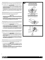
B
La guida inferiore deve essere rettilinea, orizzontale (in bolla) ed in buono
stato. Controllare che le ruote siano appropriate al tipo di guida utilizzato.
ATTENZIONE
• La struttura del cancello deve essere tale da soddisfare le esigenza
previsti dalle vigenti norme di sicurezza (UNI 8612), specie per
quanto riguarda i punti in cui vi possono essere pericoli di schiac-
ciamento o cesoiamento .
• Alla guida inferiore deve essere saldato un fermo di arresto dell’anta
in apertura (B 1 ➀), onde evitare un’eventuale uscita del cancello
dalla guida e conseguente PERICOLOSO RIBALTAMENTO dell’an-
ta.
GUIDE INFERIORI (B 1)
LOWER GUIDES (B1)
The lower guide must be straight, level, and in good condition.
The wheels must be appropriate to the type of slides used.
WARNING
• The structure of the gate must comply with the existing safety
regulations, specially in the points where there could be a squashing
or cutting danger.
• A mechanical stop of the gate in opening (B1
➀
) must be welded to
the lower guide, to prevent the gate leaf from slipping off the guide
and, consequently, the DANGER OF FALLING OVER.
GUIDES INFERIEURS (B 1)
Le guide inférieur doit être droit, horizontal (de niveau) et en bon état.
Contrôler si les roues sont appropriées au type de guide utilisé.
ATTENTION
• La structure du portail doit satisfaire les exigences prévues par les
normes de sécurité en vigueur, notamment aux endroits où il peut y
avoir des risques d’écrasement ou de cisaillement.
• Au guide inférieur doit être soudée une butée d’arrêt en ouverture (B
1 ➀) afin d’éviter que le portail ne sorte éventuellement du guide
provoquant ainsi un DANGEREUX BASCULEMENT du portail même.
UNTERE LAUFBAHNEN (B 1)
Die untere Laufbahn muß gerade, waagerecht und in gutem Zustand sein.
Kontrollieren, ob die Räder auf den verwendeten Laufbahnstyp passen.
ACHTUNG
• Die Struktur des Tores soll den geltenden Sicherheitsnormen ent-
sprechen und zwar ganz besonders dort, wo Einklemm- und Schneid-
gefahren bestehen.
• Auf der unteren Laufbahn muß ein Sicherheitsanschlag für die
Toröffnung (B1
➀
), angeschweißt sein. Damit soll vermieden wer-
den, daß das Tor aus seinen Laufbahnen heraustritt und umkippt,
was besonders GEFÄHRLICH ist.
GUIAS INFERIORES (B 1)
La guía inferior debe ser rectilínea, horizontal y estar en buen estado.
Controlar que las ruedas sean apropiadas al tipo de guía utilizado.
ATENCION
• La estructura de la puerta debe satisfacer las exigencias previstas
por las normas vigentes de seguridad principalmente en lo que
respecta a los puntos en los que pudiera existir peligros de
aplastamiento o cizallamiento.
• A la guía inferior habrá que soldar un tope de puerta en apertura (B1
➀), para evitar una ocasional salida de la puerta del carril y en
consecuencia un VUELCO PELIGROSO de ésta.
B 1
GUIDA A SEZIONE TRIANGOLARE
V-PROFILE GUIDE
GUIDE A SECTION TRIANGULAIRE
LAUFBAHN MIT DREIECKSCHMITT
GUÍA DE SECCIÓN TRIANGULAR
GUIDA A SEZIONE ROTONDA
ROUNDED-PROFILE GUIDE
GUIDE A SECTION ARRONDIE
LAUFBAHN MIT RUNDSCHMITT
GUÍA DE SECCIÓN REDONDA

10
AP006 P10
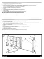
GUIDE SUPERIORI
Le guide superiori devono essere almeno due e disposte linearmente con l’anta, devono impedire che il cancello oscilli durante la corsa e non devono creare
resistenza al moto. In fig. B2 si riportano alcuni esempi di installazione.
UPPER GUIDES
There must be at least two upper guides fitted linear with the gate, which must prevent the gate from swaying during its travel, and they should not create a
hindrance to movement. Fig. B2 shows some examples of installation.
GUIDES SUPERIEURS
Les guides supérieurs doivent être au moins au nombre de deux et bien alignés au portail, doivent en empêcher l’oscillation pendant la course et ne doivent
pas créer de résistance au mouvement. La fig. B 2 montre quelques exemples d’installation.
OBERE LAUFBAHNEN
Die aberen Laufbahnen müssen mindestens zwei sein und geradlinig zum Torflügel verlaufen. Sie sollur ein Schwingen des Tores wahrend seines Laufes
sowie Widerstände während der Bewegung vermeiden. Abbildung B2 zeigt einige Installations beispiele.
GUIAS SUPERIORES
Las guías superiores deben ser como mínimo dos, y en línea con la puerta, deben impedir que ésta oscile durante su recorrido y no han de obstaculizar el
movimiento. En la fig. B2 se reflejan algunos ejemplos de instalación.
B 2
B

11
AP006 P11
RUOTE (B 3)
Le ruote devono essere di dimensioni compatibili con il profilo della guida e devono essere in buono stato; se necessario SOSTITUIRLE. Inoltre esse devono
essere NON PIÙ DI DUE e poste in prossimità delle estremità dell’anta. Aprimatic fornisce diversi tipi di ruote le cui dimensioni e la relativa portata sono descritte
in figura B 3. Nella scelta delle ruote occorre considerare, oltre alla portata, che maggiore è il diametro, migliore risulta la scorrevolezza dell’anta. Si consiglia,
inoltre, di non usare ruote di diametro inferiore a 120 mm.
WHEELS (B3)
The wheels must match the guide profile and must be in good condition. If not, REPLACE THEM. Moreover, they should NOT BE MORE THAN TWO, placed
close to either end of the gate. Aprimatic supplies different types of wheels; the sizes and relative capacities are indicated in figure B3. When choosing the
wheels, apart from the bearing, it must be considered that greater is the diameter, better is the sliding movement of the gates. We suggest not to use wheels
with diameters greater than 120 mm.
ROUES (B 3)
Les roues doivent avoir des dimensions compatibles avec la forme du guide et doivent être en bon état. Si nécessaire, LES REMPLACER. En outre il n’en
faut PAS PLUS DE DEUX et elles doivent être placées près des deux extrémités du portail. Aprimatic fournit plusieurs types de roues dont les dimensions
et la portée correspondante sont indiquées en figure B 3. Choisir les roues non seulement en fonction de la portée mais aussi du diamètre: de grandes roues
permettent d’obtenir un meilleur roulement. Nous conseillons également de ne pas utiliser de roues ayant un diamètre inférieur à 120 mm.
RÄDER (B3)
Die Dimensionen der Räder müssen mit dem Profil der Laufbahn vertragbar und in gutem Zustand sein (Falls nötig AUSWECHSELN. Es dürfen außerdem
NICHT MEHR ALS ZWEI Räder (in Nähe der Flügelenden) befestigt sein. Aprimatic liefert verschiedene Radtypen, deren Maße und Leistung auf Abbildung
3 beschrieben werden. Bei der Wahl der Räder sollte zusätzlich zur Tragleistung der Räder berücksichtigt werden, daß der Torflügel um so gleitfähiger sein
wird, je größer der Durchmesser der Räder ist. Von Rädern, deren Durchmesser kleiner als 120 mm ist, wird abgeraten.
RUEDAS (B3)
B 3
DAB
atatrop
yticapac
eétrop
gnutsiel
osep
0210343gK053
0610344gK044
0020344gK065
DABC
atatrop
yticapac
eétrop
gnutsiel
osep
021034302gK024
061034402gK035
002034402gK006
Las ruedas deben ser de dimensiones compatibles con el perfil de la guía y estar en buen estado. Si es necesario, SUSTITUIRLAS . Además no deben ser
MAS DE DOS y estar alojadas cerca de las dos extremidades de la puerta. Aprimatic suministra varios tipos de ruedas cuyas dimensiones y correspondiente
carga útil, están descritas en la figura B3. En la elección de las ruedas hay que tener en cuenta además de la carga útil, el hecho de que mayor es el diámetro,
mejor es el deslizamiento de la puerta. Se aconseja además, no usar ruedas con un diámetro inferior a 120mm.
B

12
AP006 P12
DISTRIBUTION DES ELEMENTS COMPOSANT LE MOTOREDUCTEUR (B 4)
A - Lampe clignotante Aprimatic (placer à un endroit bien visible des deux côtés du passage)
B - Photocellule de sécurité Aprimatic
C - Dispositif de commande manuelle à clé (magnétique, digital, clavier à combinaison, etc.)
D - Armoire de commande Aprimatic (à placer, si possible, à l’abri des agents atmosphériques ou bien à l’intérieur du motoréducteur
Note: dans ONDA 500E/ONDA 800E, l’appareil T2B se trouve sur le moteur.
E - Récepteur radiocommande Aprimatic (Voir catalogue)
F - Conduite pour le câble d’alimentation du motoréducteur provenant de l’armoire de commande
G - Antenne
H - Motoréducteur Aprimatic ONDA 500 ou ONDA 800
I - Carte pour ouverture partielle (passage piéton) - OPTION (Voir catalogue Aprimatic)
L - Butée mécanique en ouverture
M - Mise à la terre des structures métalliques
N - Tranche de sécurité ou profil anti-choc inerte (Voir catalogue)
N.B.: Si vous désirez ajouter d’autres dispositifs de sécurité (OPTIONS), veuillez consulter le tarif.
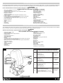
DISPOSIZIONE DEI COMPONENTI (B 4)
A - Lampeggiatore Aprimatic (posizionare in un punto ben visibile da entrambi i lati del transito)
B - Fotocellula di sicurezza Aprimatic
C - Dispositivo di comando manuale a chiave (magnetica, digitale, combinatore a tastiera, ecc.)
D - Apparecchiatura di comando Aprimatic (posizionare, possibilmente, al riparo da agenti atmosferici oppure all’interno del motoriduttore
NOTA: nella ONDA 500E/ONDA 800E l’apparecchiatura T2B é a bordo del motore
E - Radioricevente Aprimatic - vedere listino
F - Condotta per cavo di alimentazione del motoriduttore proveniente dalla apparecchiatura di comando
G - Antenna
H - Motoriduttore Aprimatic ONDA 500 o ONDA 800
I - Scheda per apertura parziale scorrevole (pedonale) - OPTIONAL (vedere listino Aprimatic)
L - Arresto meccanico in apertura
M - Messa a terra delle strutture metalliche
N - Costa sensibile o profilo antiurto inerte (vedere listino)
N.B.: Per ulteriori dispositivi di sicurezza (OPTIONAL) consultare il listino prezzi.
ARRANGEMENT OF THE COMPONENTS (B4)
A - Aprimatic flashing lamp (place in a position that is clearly visible from either side)
B - Aprimatic safety photocell
C - Manual key control device (magnetic, digital, pushbutton combination, etc.)
D - Aprimatic microprocessor control unit (shelter, where possible, from atmospheric agents or inside the geared-motor
Note: in ONDA 500E/ONDA 800E, the T2B appliance is located on the motor
E - Aprimatic Radio-receiver unit - see price list.
F - Cable-way for power supply for geared-motor from the control unit.
G - Antenna
H - Aprimatic geared-motor ONDA 500 or ONDA 800
I - Card for partial sliding opening (pedestrians) - OPTIONAL (see Aprimatic price list)
L - Mechanical opening stop
M - Earth for metal structures
N - Safety edge (active or not active profile) (see price list)
N.B. For other safety devices (OPTIONAL) refer to price list.
B
La pagina sta caricando ...

14
AP006 P14
B
ASSESSING AUTOMATION SELECTED
For a correct choice of the type of geared-motor and the type of installation to be used, experience is very important; there are however some objective criteria
that can be of help, as described below:
- Select the pinion according to the estimated weight of the gate (see TECHNICAL DATA). If the gates are less than 300 kg, it is possible to use the Z 20
pinion, but only if the sliding movement is particularly good (the Z 20 pinion must be ordered separately).
- With wooden or very old gates use the Z 16 pinion.
- With wooden gates, it is better to use the plastic rack by verifying the good conditions of the wood in the fixing points.
- The ONDA 500 / ONDA 800 isn’t totally waterproof: therefore we recommend installing the geared-motor slightly raised off the ground. In some areas (where
heavy snow occurs or there are flooding risks) the geared-motor can be placed at a height of 20-30 cm.
- Choose the type of fixing (with a foundation plate or with screw anchors) on the basis of the available consistency. Remember that the fixing with screw
anchors can be done if the fixing base is good, the support is flat and levelled.
SELECTING SAFETY DEVICES
Apart from the flashing lamp and the photocells, the ONDA 500 / ONDA 800 series make available the following safety systems:
- Clutch (part of geared-motor)
- Active safety edges
All the electric safety devices can be handled by the Aprimatic control units.
ATTENTION
• The selection and installation of the components and safety devices should be performed in compliance with the existing safety regulations.
ATTENTION
• The safety devices to prevent squashing are effective when used in appropriate situations. READ CAREFULLY THE WARNINGS GIVEN BELOW.
VERIFICATION DU CHOIX DE L’AUTOMATISATION
Pour bien choisir le type de motoréducteur et le type d’installation à réaliser, l’expérience est très importante; on peut toutefois s’aider de critères objectifs,
comme décrit ci-après:
- Choisir le pignon en fonction du poids estimé du portail (voir DONNEES TECHNIQUES). Dans le cas de vantaux pesant moins de 300 Kg, on peut utiliser
le pignon Z 20 mais uniquement si le portail roule très bien (le pignon Z 20 doit être commandé à part).
- Avec des vantaux en bois ou très vieux, utiliser le pignon Z 16.
- Avec des vantaux en bois, nous conseillons d’utiliser la crémaillère en plastique en vérifiant le bon état du bois aux endroits de fixation.
- L’ONDA 500 / ONDA 800 n’est pas étanche:c’est pourquoi nous conseillons de placer le motoréducteur légèrement au-dessus du sol. Dans certaines
zones (où il neige beaucoup ou bien innondées par d’importants écoulements d’eaux), il convient de placer le réducteur à 20 / 30 cm au-dessus du sol.
- Choisir le type de fixation (par plaque de fondation ou par vis) en fonction de la consistance de la surface. Nous vous rappelons que la fixation par vis
ne peut être effectuée que si la consistance de la base de fixation est bonne, la surface d’appui bien plate et de niveau.
CHOIX DES DISPOSITIFS DE SECURITE
En plus de la lampe clignotante et des photocellules, la série ONDA 500 / ONDA 800 dispose des systèmes de sécurité suivants:
- Embrayage (incorporé dans le motoréducteur).
- Tranches de sécurité
Toutes les sécurités électriques peuvent être gérées par les armoires de commande Aprimatic.
ATTENTION
• Le choix et l’installation des éléments composant le motoréducteur et des dispositifs de sécurité doivent être effectués de façon à respecter
les normes de sécurité en vigueur.
ATTENTION
• Les dispositifs anti-écrasement sont efficaces s’ils sont utilisés comme leur emploi le prévoit. LIRE ATTENTIVEMENT LES RECOMMANDA-
TIONS FIGURANT CI-APRES.
VERIFICA SCELTA AUTOMAZIONE
Per la corretta scelta del tipo di motoriduttore e del tipo di installazione da realizzare l’esperienza è molto importante; tuttavia può essere utile aiutarsi con criteri
oggettivi, come descritto di seguito:
- Scegliere il pignone in base al peso stimato del cancello (vedere DATI TECNICI). Nel caso di ante inferiori ai 300 kg è possibile usare il pignone Z 20,
ma solo se la scorrevolezza particolarmente buona (il pignone Z 20 va ordinato a parte).
- Con ante di legno o molto vecchie usare il pignone Z 16
- Con ante in legno, si consiglia di utilizzare la cremagliera in plastica verificando il buono stato del legno nei punti di fissaggio.
- L’ ONDA 500 / ONDA 800 non è a tenuta stagna: si consiglia dunque di tenere il motoriduttore leggermente sollevato da terra. In alcune zone (dove vi sono
abbondanti nevicate o rischi di allagamento) è bene tenere il riduttore sollevato di 20÷30 cm.
- Scegliere il tipo di fissaggio (mediante piastra di fondazione o mediante tasselli) in base alla consistenza disponibile. Si ricorda che il fissaggio con tasselli
può essere eseguito se la consistenza della base di fissaggio è buona, l’appoggio è piano e in bolla.
SCELTA DEI DISPOSITIVI DI SICUREZZA
Oltre al lampeggiatore ed alle fotocellule, la serie ONDA 500 / ONDA 800 mette a disposizione i seguenti sistemi di sicurezza:
- Frizione (incorporata nel motoriduttore)
- Coste sensibili
Tutte le sicurezze elettriche possono essere gestite dalle apparecchiature di comando Aprimatic.
ATTENZIONE
• La scelta e l’installazione dei componenti e dei dispositivi di sicurezza deve essere effettuata in modo tale da ottemperare alle esistenti norme
di sicurezza (UNI 8612).
ATTENZIONE
I dispositivi antischiacciamento sono efficaci se utilizzati nelle situazioni idonee al loro uso.
LEGGERE ATTENTAMENTE LE AVVERTENZE RIPORTATE DI SEGUITO.
La pagina sta caricando ...

16
AP006 P16
B
DISPOSITIVI ANTISCHIACCIAMENTO (RACCOMANDAZIONI ED AVVERTENZE)
FRIZIONE
Per la sicurezza dell’automazione la frizione del motoriduttore deve essere tarata con cura. Se il peso e la scorrevolezza dell’anta sono tali da richiedere una
regolazione della frizione oltre i limiti stabiliti dalle norme di sicurezza, si deve innalzare il livello di sicurezza dell’automazione, aggiungendo altri dispositivi,
in modo da rientrare nei requisiti delle norme di sicurezza.
COSTE SENSIBILI
Le coste si possono utilizzare in quasi tutte le situazioni; comunque esse sono indispensabili con cancelli pesanti e tarature molto spinte della frizione. Esse
possono essere montate come protezioni sia in chiusura che in apertura con ante non tamponate.
CLUTCH
To ensure the safety of the automatic control unit, the geared-motor clutch must be accurately calibrated. If the weight and the smooth sliding of the door require
clutch adjustment beyond the limits established by the safety regulations, it is necessary to increase the automation safety level by adding other devices to
comply with the safety requirements.
SAFETY EDGES
The safety edges can be used in almost all situations; but they are essential with heavy gates and extreme clutch settings. They can be fitted as opening and
closing protective devices on open bar gates.
EMBRAYAGE
Pour garantir la sécurité de l’automation, il faut veiller à bien régler l’embrayage du motoréducteur. Si le poids et le roulement du portail exigent un réglage
d’embrayage dépassant les limites établies par les normes de sécurité, il faut augmenter le niveau de sécurité de l’automatisation en ajoutant d’autres dispositifs
de façon à assurer le respect des normes de sécurité.
TRANCHES DE SECURITE
On peut utiliser les tranches dans presque toutes les situations; elles sont indispensables lorsque les portails sont lourds et les réglages de l’embrayage très
poussés. On peut les monter comme protection aussi bien en fermeture qu’en ouverture avec des vantaux non tamponnés.
EINKLEMMSCHUTZVORRICHTUNGEN (EMPFEHLUNGEN UND HINWEISE)
KUPPLUNG
Zur Sicherheit der Automation sollte die Kupplung des Getriebemotors sorgfältig kalibriert werden. Sofern das Gewicht und die Gleitfähigkeit des Torflügels
eine Nachstellung der Kupplung über die von den Sicherheitsnormen festgesetzten Grenzwerten hinaus erforderlich machen, so ist das Sicherheitsniveau der
Automation durch Einsetzten zusätzlicher Vorrichtungen zu erhöhen, damit die Sicherheitsanforderungen eingehalten werden können.
SICHERHEITSKONTAKTLEISTE
Diese Leisten lassen sich in fast allen Lagen einsetzen. Unersetzlich sind sie bei schwergewichtigen Schiebetoren und bei besonders hart eingestellten
Kupplungen. Sie können als Schutz für nicht Torflügel mit Planfläche beim Auf- und Zuschließen eingesetzt werden.
DISPOSITIVOS ANTIAPLASTAMIENTO (RECOMENDACIONES Y ADVERTENCIAS)
EMBRAGUE
Para la seguridad de la automatización, el embrague del motorreductor debe ser ajustado con cuidado. Si el peso y el deslizamiento de la puerta requiriesen
un ajuste del embrague superior los límites establecidos por las normas de seguridad, se debe aumentar el nivel de seguridad de la automatización, añadiendo
otros dispositivos, de manera que cumplan los requisitos de las normas de seguridad.
BANDAS SENSIBLES
Las bandas se pueden utilizar en casi todas las situaciones; pero son imprescindibles con puertas pesadas y en ajustes de embrague muy forzados. Se pueden
montar como protección tanto en el cierre como en la apertura con puertas no taponadas.
DEVICES TO PREVENT SQUASHING (ADVICE AND WARNINGS)
DISPOSITIFS ANTI-ECRASEMENT (RECOMMANDATIONS ET REMARQUES)

17
AP006 P17
B
B 6
VERIFICA COMPONENTI MOTORIDUTTORE
Prima di iniziare il montaggio controllare che l’imballo contenga tutti i componenti
elencati di seguito e che gli stessi non siano danneggiati. Verificare, inoltre,
che la sigla del modello riportata sulla scatola da imballo del motoriduttore
corrisponda a quella riportata sulla targhetta del motoriduttore stesso (B6 ➀).
CHECKING COMPONENTS OF GEARED-MOTOR
Before going ahead with assembly, check that the package contains all the
components listed below and that these are undamaged. It is also important
to check that the model code on the geared-motor packing box corresponds
to that on the geared-motor plate (B6 ➀).
VERIFICATION DES PIECES COMPOSANT
LE MOTOREDUCTEUR
Avant de commencer le montage, contrôler que l’emballage contienne toutes
les pièces énumérées ci-après et qu’elles ne soient pas endommagées.
Vérifier également si la référence du modèle indiquée sur la boîte d’emballage
correspond bien à celle figurant sur la plaquette signalétique du motoréducteur
(B 6 ➀).
KONTROLLE DER GETRIEBEMOTOR-BAUTEILE
Vor Beginn der Montage kontrollieren, ob alle nachstehend aufgelisteten
Teile mitverpackt wurden und ob sie nicht etwa beschädigt wurden.
Kontrollieren, ob das Kurzzeichen für das auf der Schachtel abgebildete
Getriebemotor-Modell dem auf dem Getriebemotor-Kennschild entspricht
(B6
➀
).
COMPROBACION DE LOS COMPONENTES DEL
MOTORREDUCTOR
Antes de empezar el montaje, controlar que el embalaje contenga todos los
componentes enumerados a continuación y que los mismos no estén dañados.
Comprueben además, que la sigla del modelo reflejada en la caja de embalaje
del motorreductor corresponda a la reflejada en la placa del mismo.(B6 ➀)

18
AP006 P18
LISTE DES PIECES
Contenu de l’emballage (B7)
Repère Désignation
1 Motoréducteur
2 Plaque de fixation à glissière
3 Clé de déverrouillage
4 Plaquette de fin de course q.té 2
5 Grain de fixation de plaquette q.té 4
A commander à part (OPTIONS)
6 Crémaillère en plastique + accessoires pour le montage
7 Crémaillère en acier + accessoires pour le montage
8 Plaque de fondation
9 Vis de fixation de la plaque à glissière type FISCHER S 10 RS 100 ou
équivalentes (pour montage sans plaque de fondation) - à acheter à part
Description interne (B8)
Repère Désignation
1 Embase du motoréducteur
2 Déverrouillage à clé
3 Plaque de support en plastique
4 Passe-fils
5 Bornier avec couvercle
6 Fin de course
7 Pignon
8 Moteur électrique
9 Capot
10 Vis de blocage du capot
ELENCO DEI COMPONENTI
Contenuto della confezione (B7)
Pos. Descrizione
1 Motoriduttore
2 Piastra di fissaggio a slitta
3 Chiave di sblocco
4 Piastrino fine corsa q.tà 2
5 Grano fissaggio piastrino q.tà 4
Da ordinarsi a parte (OPTIONAL)
6 Cremagliera in plastica + accessori per l’installazione
7 Cremagliera in acciaio + accessori per l’installazione
8 Piastra di fondazione
9 Tasselli di fissaggio piastra a slitta tipo FISCHER S 10 RS 100 od
equivalenti (per montaggio senza piastra di fondazione) - da acquistarsi
a parte
Descrizione interna (B8)
Pos. Descrizione
1 Basamento del motoriduttore
2 Sblocco a chiave
3 Piastra di supporto in plastica
4 Passacavi
5 Morsettiera con coperchietto
6 Finecorsa
7 Pignone
8 Motore elettrico
9 Cofano
10 Vite bloccaggio cofano
LIST OF COMPONENTS
PACKAGE CONTENTS (B7)
Pos. Description
1 Geared-motor
2 Sliding securing plate
3 Release key
4 End travel plate
5 Plate securing
dowel
To order separately (OPTIONAL)
6 Plastic rack + installation accessories
7 Galvanized steel rack + installation accessories
8 Foundation plate
9 Sliding plate securing screw anchors FISCHER S 10 RS 100 or equivalent
type (for assembly without plate foundation) - must be bought separately
Internal description (B8)
Pos. Description
1 Geared-motor base
2 Key release
3 Plastic support plate
4 Cable fittings
5 Terminal board with cover
6 Limit switch
7 Pinion
8 Electrical motor
9 Cover
10 Cover securing screw
La pagina sta caricando ...

20
AP006 P20
B
PREPARATION FOR INSTALLATION
The installation of the geared-motor requires a series of preparatory operations on the gate to be automated, if the gate is already installed, at the installation
site; it is therefore necessary to prepare the equipment that will give the installer maximum autonomy.
WARNING
The list of tools necessary is given in the figure, including the table, (B9)
BASIC EQUIPMENT AND DISPOSABLE MATERIAL REQUIRED
- Electric disk grinder: 230V
- Protective goggles
- Electric welder: 230V/100 Amp minimum
- Protective mask
- Electrodes minimum dia. 2
- Soft soldering iron
- Electric drill: 230V
- Drill bits
- Cup milling cutter dia. 67 for photocell and push-button housing holes
- Extension cable for electrical equipment
- Electric cable 1.5 mm 2 in various colours+various types of cable terminals
- Electrician’s scissors
- Cable terminal grippers
- Tester
- Calliper in twentieths
- Measuring stick
- Protractor
- Dynamometer
B 9
PREPARAZIONE AL MONTAGGIO
Il montaggio del motoriduttore richiede una serie di lavori di preparazione della porta da movimentare da eseguirsi, se la porta è già installata, direttamente
sul luogo dell’installazione; è quindi necessario premunirsi dell’attrezzatura adatta che consenta all’installatore la massima autonomia durante il lavoro.
ATTENZIONE
L’elenco dell’utensileria necessaria è riportato nella figura, comprensiva di tabella, (B 9).
ATTREZZATURA BASE E MATERIALE DI CONSUMO OCCORRENTE
- Mola a disco elettrica alimentazione: 230 V.
- Occhiali di protezione
- Saldatrice elettrica alimentazione: 230 V./100 Amp. minimo
- Maschera di protezione
- Elettrodi Ø 2 minimo
- Saldatore da stagno
- Trapano elettrico di potenza adeguata alimentazione: 230 V.
- Punte da trapano
- Fresa a tazza Ø 67 per fori alloggiamento fotocellule e pulsantiere
- Cavo di prolunga per attrezzatura elettrica
- Cavo elettrico sez. 1,5 mm 2 vari colori + capicorda vario tipo
- Forbici da elettricista
- Pinze per capicorda
- Tester
- Calibro ventesimale
- Metro
- Goniometro
- Dinamometro
- Filo a piombo
- Livella a bolla (tridimensionale)
- Grasso tipo grafitato.
- Bomboletta Zincospray
- Vernice antiruggine
- Pennelli per verniciatura
- Diluente per pulizia pennelli
- Spazzola metallica
- Lime varie
- Seghe da ferro
- Punte da tracciatura
- Martello
- Scalpello per acciaio e per muratura
- Salviette detergenti
- Carta per asciugatura mani
- Cassetta “Pronto soccorso”
- Morsetti da fabbro o pinze “grip”
- Dima per posizionamento cremagliera
- Plumb line
- Spirit level (three-dimensional)
- Graphite type grease
- Zinco spray canister
- Rust inhibitor paint
- Paint brushes
- Turpentine for cleaning paint brushes
- Metal brush
- Various files
- Iron saws
- Marking bits
- Hammer
- Metal and masonry chisels
- Wipe clean tissues
- Paper towels
- First Aid box
- Forger’s clamps or grippers
- Template for rack positioning
.SOP
/ELISNETU
LOOT
/LITUO/
GUEZKREW
SOILISNETU/
1
5,2oihcsamalogurbaevaihC
5,2yeknellA
5,2elâmnellAélC
5,2lessülhcssubmI
5,2ohcamnellAevalL
GASUGASU
5,2/082
2
4oihcsamalogurbaevaihC
4yeknellA
4elâmnellAélC
4lessülhcssubmI
4ohcamnellAevalL
GASUGASU
4/082
3
31atanibmocevaihC
31hcnerwnoitanibmoC
31eénibmocélC
31lessülhcsibmoK
31atanibmocevalL
31/582GASU
4
inretseregeesrepazniP
sgnirpanslanretxerofreppirG
serueirétxeregeesseugabruopsecniP
regeesneßuArüfegnaZ
seroiretxenóicneteredsollinaarapazniP
821GASU
01/P ÷ 52
La pagina sta caricando ...

22
AP006 P22
C
INSTALLAZIONE DELL’ AUTOMAZIONE (MODALITÀ - INGOMBRI)
L’installazione descritta in fig. C1 A-B prevede il trascinamento dell’anta mediante un accoppiamento pignone/cremagliera. Il motoriduttore è fissato al suolo
mediante l’apposita piastra a slitta che ne permette un’agevole registrazione della posizione assiale.
La piastra a slitta, a sua volta, può essere saldata ad una piastra di fondazione (C1 A) , oppure (se la consistenza della base lo consente) fissata al suolo
mediante tasselli ad espansione o chimici (C1 B).
Vengono descritti, inoltre, gli ingombri tipici da controllare durante il sopralluogo (vedere anche fig. C11 per l’ingombro ed il posizionamento della cremagliera).
Il pignone dell ONDA 500 / ONDA 800 è compatibile sia con la cremagliera in plastica (con anima in acciaio) che con quella in acciaio zincato.
ATTENZIONE
È essenziale che, durante il sopralluogo, l’installatore verifichi che vi sia nei pressi dell’anta lo spazio necessario per poter rispettare gli ingombri
riportati nei disegni.
INSTALLATION OF AUTOMATIC CONTROL UNIT (MODALITY - LAYOUTS)
The installation shown in figure C1 A-B considers the one in which the gate is driven by a rack and pinion system. Geared-motor is secured into the ground
with the appropriate sliding plate which permits an easy adjustment of the axial position.
The sliding plate itself can be welded to a foundation plate (C1 A), or (if the base is strong enough) secured into the ground with screw anchors (C1 B) and
chemical ones.
A description is also given of the typical layout that must be controlled when the site is inspected (see also fig. C11 for the layout and the positioning of the
rack).
The ONDA 500 / ONDA 800 pinion is compatible both with the plastic rack (with a steel core) and with the galvanized steel rack.
ATTENTION
It is essential that, when the site is inspected, the installer makes sure that there is sufficient room near the gate for the layouts illustrated in the
drawings.
INSTALLATION DE L’AUTOMATISATION (MODALITES - ENCOMBREMENTS)
L’installation décrite en figure C1 A-B prévoit l’entraînement du portail au moyen d’un couplage pignon-crémaillère. Le motoréducteur est fixé au sol au moyen
de la plaque à glissière qui permet de régler facilement la position axiale.
La plaque à glissière, à son tour, peut être soudée à une plaque de fondation (C1 A) ou bien (si la consistance de la base le permet) fixée au sol par des vis
tamponnées ou chimiques (C1 B).
Nous indiquons également les encombrements typiques à contrôler au préalable (voir aussi fig.C11 pour l’encombrement et le positionnement de la
crémaillère).
Le pignon de l’ONDA 500 / ONDA 800 est compatible aussi bien avec la crémaillère en plastique (avec âme en acier) qu’avec celle en acier zingué.
ATTENTION
Il est essentiel que l’installateur vérifie au préalable s’il y a autour du portail la place nécessaire pour pouvoir respecter les encombrements indiqués
sur les schémas.
La pagina sta caricando ...

24
AP006 P24
C
FONDAZIONE
Il buon funzionamento di ogni automazione scorrevole esige che il motoriduttore venga ancorato ad una struttura atta ad assicurarne il buon fissaggio, ed il
buon allineamento con l’anta.
ATTENZIONE
È fondamentale che l’opera di fondazione sia eseguita a regola d’arte e che la piastra venga posizionata correttamente rispetto all’anta in modo
tale che il motoriduttore sia ben allineato con la guida del cancello, alla giusta distanza dall’anta, alla giusta profondità, e con il pozzetto dei cavi
elettrici al posto giusto (C2).
Tenere presente anche i seguenti punti:
- Fare attenzione al senso di apertura dell’anta in relazione alla posizione del pozzetto dei cavi (C2).
- Tenere conto della posizione di fissaggio della cremagliera per la posizione in verticale del piano di appoggio (Fig. C11-C12).
- Evitare di realizzare la fondazione con al base di appoggio sotto il livello del terreno circostante; semmai sopraelevarla di qualche cm.
ATTENZIONE
Nelle zone molto nevose od in punti a rischio di allagamento si consiglia di posizionare la piastra anche 20÷30 cm oltre la superficie del suolo.
FOUNDATION
Correct functioning of any automatic sliding system depends on the geared-motor being firmly anchored to a structure designed to hold it securely, and good
alignment with the gate.
ATTENTION
It is essential that the foundation be prepared precisely with the foundation plate in the right position with respect to the gate. The geared-motor
must be correctly aligned with the gate guide, at the correct distance from the gate, at the right depth, and the electric cable passage bore in the
correct position (C2).
Remember also the following points:
- Check the gate opening direction in relation to the position of the cable hole (C2).
- Consider the fixing position of the rack for the vertical position of the supporting surface (C11-C12).
- Avoid executing the foundation with the supporting base below the surface of the ground surrounding the installation; it should be raised a few cm.
WARNING
In areas subject to heavy snow or with flood risks, the plate should be placed at 20÷30 cm above the ground.
FONDATION
Le bon fonctionnement de toute automatisation roulante exige que le motoréducteur soit fixé à une structure qui puisse en assurer la bonne fixation et le bon
alignement avec le portail.
ATTENTION
Il est fondamental que le travail de fondation soit effectué selon les normes et que la plaque soit bien placée par rapport au portail de telle sorte
que le motoréducteur soit bien aligné au guide du portail, à la bonne distance et à la bonne profondeur et que le trou de passage des câbles soit
bien situé (C2).
Il faut aussi:
- Veiller au sens d’ouverture du portail en fonction de l’emplacement du trou de passage des câbles (C 2).
- Tenir compte de l’emplacement de fixation de la crémaillère pour la position à la verticale du plan d’appui.(Fig. C11-C12)
- Eviter de réaliser la fondation avec la base d’appui au-dessous du niveau du terrain environnant; placez-la plutôt quelques centimètres au-dessus du sol.
ATTENTION
Dans les zones où il neige beaucoup ou bien inondées par d’importants écoulements d’eaux, nous conseillons de placer la plaque jusqu’à 20 ÷30
cm au-dessus du sol.
La pagina sta caricando ...

26
AP006 P26
C
A - FISSAGGIO CON TASSELLI
Se la zona nella quale andrà fissato il motoriduttore è già in cemento di buona
consistenza ed è in bolla, allora è possibile fissare la piastra di fissaggio
direttamente al terreno con TASSELLI AD ESPANSIONE PER MURATURE
COMPATTE. (Usare tasselli Fischer S 10 RS 100, od equivalenti, oppure un
fissaggio mediante tasselli chimici).
ATTENZIONE
La piastra deve risultare ben allineata con l’anta scorrevole ed alla
corretta distanza dal piano di appoggio della cremagliera (58÷62 mm -
C3); inoltre, se vi è un pozzetto per il passaggio dei cavi, essa deve
essere posizionata alla giusta distanza da esso (C4).
ATTENZIONE
Usare tutti e quattro i fori di fissaggio (C4 ➀) ed assicurarsi che la piastra
sia solidale al terreno.
A - SECURING WITH SCREW ANCHORS
If the area where the geared-motor is to be fitted already has a good level
cement surface, the securing plate can be screwed directly into the ground
with COMPACT BUILDING SCREW ANCHORS. (Use Fischer S 10 RS 100,
or equivalent, or securing with chemical screw anchors).
ATTENTION
The plate must be aligned with the sliding gate and at the correct
distance from the supporting surface of the rack (58+62 mm - C3);
moreover, if there is a hole for the fitting of the cables, it must be
positioned at the correct distance from it (C4).
ATTENTION
Use all four fixing holes (C4
➀
) and make sure the plate is integral with
the ground.
A - FIXATION PAR VIS
Si la zone où sera fixé le motoréducteur est déjà en béton ayant une bonne
consistance et est de niveau, on peut fixer la plaque de fixation directement
au terrain par des VIS POUR MAÇONNERIES COMPACTES. (Utiliser des
vis Fisher S 10 RS 100 ou équivalentes, ou bien une fixation par vis
chimiques).
ATTENTION
La plaque doit être bien alignée avec le portail roulant et bien située par
rapport au plan d’appui de la crémaillère (58 à 62 mm - C3); de plus, s’il
y a un trou pour le passage des câbles, elle doit être également bien
positionnée par rapport celui-ci (C4).
ATTENTION
Utiliser les quatre trous de fixation (C4 ➀) et contrôler si la plaque est
bien solidaire du terrain.
C 3
A - SECURING WITH SCREW ANCHOR
La pagina sta caricando ...

28
AP006 P28
C
B-FISSAGGIO MEDIANTE PIASTRA DI FONDAZIONE
Il fissaggio tramite piastra di fondazione richiede la posa di una fondazione,
ex novo, in cui viene inserita la piastra.
ATTENZIONE
Posizionare la piastra di fondazione con il pozzetto dei cavi orientato in
modo congruente con il verso corretto di apertura del cancello (vedi C2
a pag.23).
Posa della piastra di fondazione
- Eseguire un pozzetto per il passaggio dei cavi per tubi Ø 30 mm MAX. in
corrispondenza dell’asola ricavata nella piastra di fondazione.
- Ripiegare le quattro graffe della piastra di fondazione nel modo indicato
in C5.
- Riempire il pozzetto di cemento di buona qualità, inserire la piastra nel
pozzetto e controllare il perfetto posizionamento ed allineamento della
piastra con l’anta (C6 ➀).
ATTENZIONE
Si consiglia di proteggere la superficie della piastra di fondazione con
Zincospray o vernice antiruggine.
Montaggio della piastra a slitta
- Eliminare eventuali sbavature di cemento, o ruggine sulla superficie della
piastra, specie sulle tacche di riferimento (C6 ➁).
- Posizionare la piastra a slitta in corrispondenza delle tacche (C6 ➁) ed
allinearla alla giusta distanza dall’anta (C7).
- Saldarla SOLO sui lati corti.
ATTENZIONE
Proteggere le saldature e la parte sporgente della piastra di fondazione
con Zincospray.
C 5
C 6
C 7
B - SECURING WITH A FOUNDATION PLATE
The securing with a foundation plate requires the positioning of a foundation,
ex novo, where the plate is embedded.
ATTENTION
Position the foundation plate with the cable hole placed adequately with
the correct direction of the gate opening (see C2 at page 23).
Foundation plate positioning
- Execute a hole for the fitting of the cables for 30 mm diameter tubes MAX.
in connection with the slot in the foundation plate.
- Fold the four straps of the foundation plate in the way indicated in C5.
- Fill the hole with good quality cement, insert the plate in the hole and check
the perfect positioning and aligning of the plate with the gate (C6
➀
).
ATTENTION
The surface of the foundation plate must be protected with Zinc spray
or rust inhibitor paint.
Fitting the sliding plate
- Clean possible cement splashes or rust on the surface of the plate,
specially on the reference marks (C6
➁
).
- Position the sliding plate in connection with the reference marks (C6
➁
)
and align it at the correct distance from the gate (C7).
- Weld ONLY on the shorter sides.
ATTENTION
Protect the welds and the projecting part of the foundation plate with
Zinc spray.
La pagina sta caricando ...
La pagina sta caricando ...
La pagina sta caricando ...
La pagina sta caricando ...
La pagina sta caricando ...
La pagina sta caricando ...
La pagina sta caricando ...
La pagina sta caricando ...
La pagina sta caricando ...
La pagina sta caricando ...
La pagina sta caricando ...
La pagina sta caricando ...
La pagina sta caricando ...
La pagina sta caricando ...
La pagina sta caricando ...
La pagina sta caricando ...
La pagina sta caricando ...
La pagina sta caricando ...
La pagina sta caricando ...
La pagina sta caricando ...
La pagina sta caricando ...
La pagina sta caricando ...
La pagina sta caricando ...
La pagina sta caricando ...
La pagina sta caricando ...
La pagina sta caricando ...
La pagina sta caricando ...
La pagina sta caricando ...
La pagina sta caricando ...
La pagina sta caricando ...
La pagina sta caricando ...
-
 1
1
-
 2
2
-
 3
3
-
 4
4
-
 5
5
-
 6
6
-
 7
7
-
 8
8
-
 9
9
-
 10
10
-
 11
11
-
 12
12
-
 13
13
-
 14
14
-
 15
15
-
 16
16
-
 17
17
-
 18
18
-
 19
19
-
 20
20
-
 21
21
-
 22
22
-
 23
23
-
 24
24
-
 25
25
-
 26
26
-
 27
27
-
 28
28
-
 29
29
-
 30
30
-
 31
31
-
 32
32
-
 33
33
-
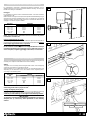 34
34
-
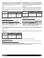 35
35
-
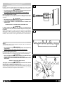 36
36
-
 37
37
-
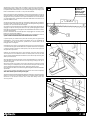 38
38
-
 39
39
-
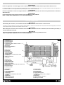 40
40
-
 41
41
-
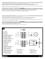 42
42
-
 43
43
-
 44
44
-
 45
45
-
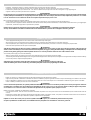 46
46
-
 47
47
-
 48
48
-
 49
49
-
 50
50
-
 51
51
-
 52
52
-
 53
53
-
 54
54
-
 55
55
-
 56
56
-
 57
57
-
 58
58
-
 59
59


Aprimatic ONDA 500 EZ Manuale del proprietario
- Categoria
- Gate Opener
- Tipo
- Manuale del proprietario
in altre lingue
Documenti correlati
Altri documenti
-
Key Gates Turbo 30 Guida utente
-
Chamberlain LiftMaster SLY250 Manuale del proprietario
-
 Beninca DUCNI/DUCZS Guida utente
-
Tau F10 – F15 Series Manuale del proprietario
-
 DITEC CROSS 3E Manuale del proprietario
-
Genius Falcon Manuale utente
-
Genius FALCON 5M 8M 424M Istruzioni per l'uso
-
-
-
DITEC CROSS30E Manuale del proprietario

