
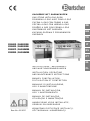
GASH ERD E MIT G A SBACK OFEN
GAS STOVE WITH GAS OVEN
FOURNEAU À GAZ AVEC FOUR À GAZ
CUCINA A GAS CON FORNO A GAS
COCINA A GAS CON HORNO A GAS
FOGÕES A GÁS COM FORNO A GÁS
GASFORNUIS MET GASOVEN
KUCHNIA GAZOWA Z PIEKARNIKIEM
GAZOWYM
Rev.-Nr.: 01-2017
INSTALLATIONS-, BEDIENUNGS-
UND WARTUNGSANWEISUNGEN
INSTALLATION, OPERATING
AND MAINTENANCE NSTRUCTIONS
MANUEL D'INSTALLATION,
D'UTILISATION ET D'ENTRETIEN
MANUALE DI INSTALLAZIONE,
USO E MANUTENZIONE
MANUAL DE INSTALACIÓN,
USO Y MANTENIMIENTO
MANUAL DE INSTALAÇÃO,
UTILIZAÇÃO E MANUTENÇÃO
HANDLEIDING VOOR INSTALLATIE,
GEBRUIK EN ONDERHOUD
W SK AZÓW KI DOT YCZĄ CE INSTALACJI,
UŻYTKOW ANIA I KONS ERWACJI
DE
GB
FR
IT
ES
PT
NL
PL
2951131 / FA092M00
2951121 / FA093M00
2952171 / FAG92M00
2952291 / FAG93M00

TECHNISCHE ÄNDERUNGEN VORBEHALTEN!
TECHNICAL CHANGES RESERVED!
SOUS RÉSERVE DE MODIFICATIONS TECHNIQUES !
CI RISERVIAMO LA POSSIBILITÀ DI INTRODURRE MODIFICHE TECNICHE!
¡SE RESERVA EL DERECHO A INTRODUCIR MODIFICACIONES TÉCNICAS!
SUJEITO A ALTERAÇÕES TÉCNICAS!
TECHNISCHE WIJZIGINGEN VOORBEHOUDEN!
WPROWADZANIE ZMIAN TECHNICZNYCH ZASTRZEŻONE!
PL
IT
DE
PT
NL
ES
FR
GB

1
ENGLISH
GB
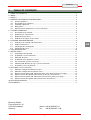
1. TABLE OF CONTENTS
1. TABLE OF CONTENTS ..................................................................................................................... 1
2. INDEX ................................................................................................................................................. 2
3. SAFETY .............................................................................................................................................. 3
4. GENERAL INFORMATION AND WARNINGS ................................................................................... 4
4.1. General guidelines ................................................................................................................... 4
4.2. Description of the appliance ..................................................................................................... 4
4.3. Protection appliances ............................................................................................................... 5
4.4. Rating plate .............................................................................................................................. 5
4.5. Replacement of components (service technician) ................................................................... 6
5. USE AND OPERATION ..................................................................................................................... 6
5.1. Description of the controls. ....................................................................................................... 6
5.2. Ignition of gas stove burners .................................................................................................... 7
5.3. Ignition of oven burners ............................................................................................................ 7
5.4. Guidelines on how to use the device ....................................................................................... 8
6. CLEANING AND MAINTENANCE ..................................................................................................... 8
6.1. Guidelines on cleaning and maintenance ................................................................................ 8
6.2. Proper maintenance ................................................................................................................. 8
6.3. Cleaning of the heating plate ................................................................................................... 9
6.4. Cleaning of the oven ................................................................................................................ 9
7. TROUBLESHOOTING ..................................................................................................................... 10
8. INSTALLATION ................................................................................................................................ 11
8.1. Packaging and unpacking ...................................................................................................... 11
8.2. Installation (service technician) .............................................................................................. 11
8.3. Extraction of fumes ................................................................................................................. 12
8.4. Installation of the appliance in a line ...................................................................................... 12
8.5. Gas connection (service technician) ...................................................................................... 12
8.6. Switching into different gas type (service technician) ............................................................ 13
8.7. Inspection (service technician) ............................................................................................... 13
9. SETTINGS (service technician)........................................................................................................ 13
9.1. Minimum setting of the hob burner valve ............................................................................... 14
9.2. Minimum setting of the oven burner valve ............................................................................. 14
9.3. Replacement of nozzle and adjustment of gas stove burner primary air supply ................... 15
9.4. Replacement of the ignition flame nozzles of the gas stove burners ..................................... 15
9.5. Replacement of nozzle and adjustment of oven burner primary air supply ........................... 16
9.6. Replacement of the ignition flame nozzle of the oven burners .............................................. 16
10. APPLIANCE DISPOSAL .................................................................................................................. 17
ATTACHMENTS ....................................................................................................................................... I
Bartscher GmbH
Franz-Kleine-Str. 28
D-33154 Salzkotten phone: +49 (0) 5258 971-0
Germany fax: +49 (0) 5258 971-120

2
ENGLISH
GB
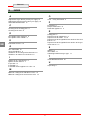
2. INDEX
A
Adjustment of gas burner primary air supply 15
Adjustment of oven burner primary air supply 16
APPLIANCE DISPOSAL 17
C
Cleaning of the heating plate 9
Cleaning of the oven 9
D
Description of the appliance 4
Description of the controls 6
E
Extraction of fumes 12
G
Gas connection 12
General guidelines 4
Guidelines on cleaning and maintenance 8
Guidelines on how to use the device 8
I
Ignition of gas stove burners 7
Ignition of oven burners 7
Inspection 13
Installation 11
Installation of the appliance in a line 12
M
Minimum setting of the hob burner valve 14
Minimum setting of the oven burner valve 14
O
Oven - safety thermostat 5
P
Packaging 11
Proper maintenance 8
Protection appliances 5
R
Rating plate 5
Replacement of components 6
Replacement of nozzle 15, 16
Replacement of the ignition flame nozzle of the oven
burners 16
Replacement of the ignition flame nozzles of the gas
stove burners 15
S
SAFETY 3
SETTINGS 13
Switching into different gas type 13
T
TROUBLESHOOTING 10
U
Unpacking 11

3
ENGLISH
GB
3. SAFETY
Read carefully the guidelines and
instructions in the instruction manual
before you use the appliance.
The instruction manual contains general
information on how to safely use and maintain the
appliance.
Retain the manual for future reference.
The manufacturer took extra care when designing
and manufacturing to prevent any safety or health
hazard to the personnel operating the appliance.
Please read carefully the guidelines in the
instruction manual and instructions placed directly
onto the appliance. Above all, observe all the
safety instructions.
Do not intervene in or remove the protective
appliances installed in the appliance. Non-
compliance may lead to severe safety and health
hazard against people. We recommend to perform
a few tests to know the layout and main functions
of the control panel, particularly those to switch
the appliance on and off.
The appliance is intended only for the use it has
been designed for and any other use is
considered as the use not in compliance with the
intended use.
The manufacturer is not liable for material
damage or damage to person caused by
misapplication or incorrect application of the
appliance.
Any maintenance work that requires special
technical licence or special skills may be
performed by qualified personnel only.
To provide hygiene and protect foods from dirt, all
the elements that have direct or indirect contact
with the foods and all border areas must be
thoroughly cleaned. Use only the cleaning agents
intended for use in contact with food and avoid
using flammable agents or harmful to health.
After each use of the appliance
make sure that all the heating
elements and control elements have
been switched off and the gas supply
connections are disconnected.
The device requires some safety measures
during installation, positioning, fixing, and connecting
to the power supply (section 8 “INSTALLATION”).
In case of longer standstill disconnect all
power supply cables and thoroughly clean the
inside and outside elements of the device (section
6 “CLEANING AND MAINTENANCE”).
Do not clean the device with direct
stream of water.

4
ENGLISH
GB
4. GENERAL INFORMATION AND WARNINGS
4.1. General guidelines
The manual has been edited by the manufacturer
to provide the authorized personnel with the
information necessary to work with the appliance.
We recommend the intended readers to read the
manual carefully and comply with the information.
By reading the information contained in the
manual, hazards against people health and safety
may be prevented.
Retain the manual in an easily available place
throughout the time of use of the appliance to
have access and refer to the required information
at any time.
Special symbols, described below, have been
used to stress important information or draw
attention to essential data:
Caution - warning
Indicate important safety
instructions. You should acquire the
proper conduct to prevent hazard
against people health and safety or not
to cause any damage.
Important
Indicate essentials technical data that
you cannot ignore.
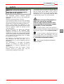
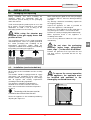
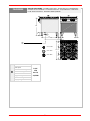
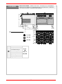
4.2. Description of the appliance
THE GAS STOVE WITH GAS OVEN, called
hereinafter the device, has been designed and
manufactured for preparation of food products in
the professional gastronomy sector.
1) Hob
2) Oven
3) Adjustable feet
4) Gas connection
5) Gas burner: made from enameled cast
iron of various power, depending on
diameter.
6) Oven smoke extraction
7) Piezoelectric ignition for gas oven burner
8) Gas oven control knob: it adjusts the gas
supply to gas stove burners
9) Temperature control knob: it adjusts the
gas supply to the oven burner
1
2
3
4
5
6
9
8
ID 01
7

5
ENGLISH
GB
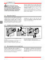
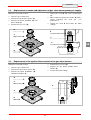
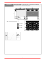
4.3. Protection appliances
The device is equipped with the following
protection systems. The drawing presents layout
of the devices.
1. Gas valve: for opening and closing the gas
supply line.
2. Safety thermocouple: cuts off the gas supply
if the flame goes out.
3. Oven-safety thermostat: in case of
overheating, the gas supply to the oven is cut
off.
Check every day that the
protection devices are mounted
correctly and operational.
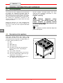
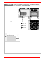
4.4. Rating plate
The rating plate shown in the drawing is fixed
directly on the device. It includes all guidelines
and information required for safe use.
1) EAN number
2) Art. no./ model no. / CE certificate no.
3) Category of device / type of design
4) Power / gas consumption / Factory setting
for specified gas type
5) Heat load
6) Production date
7) Series no.
8) CE Declaration of Conformity
9) WEEE symbol
3
Safety
thermostat
of the oven
Oven burner
protection
Gas stove burner
protection
ID
03
1
2
8
3
4
6
7
5
9

6
ENGLISH
GB
4.5. Replacement of components (service technician)
Before exchange of the
component switch on all the existing
protection appliances. First of all,
switch off the gas valve and prevent
access to the appliance, which in the
case of activation may lead to
unexpected situations endangering
the safety and health of people.
If necessary, exchange the used components to
the original spare parts.
We are not liable for personal injury or
damage to the components that arise due to
application of other spare parts than original
or intervention into the appliance without the
manufacturer’s consent that may have altered
the safety requirements.
5. USE AND OPERATION
5.1. Description of the controls.
The elements controlling the essential functions
are located on the control panel of the device.
A) Gas stove burner control knob: to
ignite, switch off or adjust a relevant
burner of the gas stove.
B) Oven burner control knob: to ignite, switch
off or adjust the oven burner.
C) Piezoelectric ignition: to ignite the
ignition flame of the oven burner.
Ignition flame
symbol
Front burners
indicator
Maximum
power
symbol
Minimum
power
symbol
Oven
temperature
Rear burners
indicator
Piezoelectric
ignition
Oven
temperature
control knob
A
A
B
C

7
ENGLISH
GB
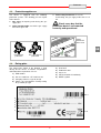
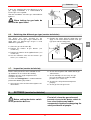
5.2. Ignition of gas stove burners
IGNITION
A) Press the control knob of the selected gas
stove burner and turn it left in order to ignite the
ignition flame (position 1). Ignite the ignition
flame with use of a match.
B) Hold the control knob pressed for approx. 10
seconds in order to heat up the thermal
element; then release the controller.
C) To ignite the gas stove burner, turn the control
knob left (position 2).
D) Set the power of the gas stove burner
(position 3).
SWITCHING OFF
A) Turn the control knob right in order to switch
the gas stove burner off (position 1).
B) To put out the ignition flame rotate the control
knob clockwise (position 0).
5.3. Ignition of oven burners
A) Press the control knob and turn it left, while
simultaneously pressing the piezoelectric
ignition a few times (C), in order to ignite the
ignition flame (position 1). Hold the control
knob pressed for approx. 10 seconds in order
to heat up the thermal element.
Hint: Ignition flame may be also ignited
manually using a match through the cover
at the oven bottom.
B) Turn the control knob left, set the
temperature between 60°C and 280°C
and wait until the oven heats up
(position 2).
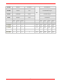
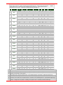
Temperature °C 60 90 120 160 200 240 280 300
Time in minutes 3 6 9 12 15 18 22 26
Pos 0
Pos 1
Pos 2
ID
05
Pos. 1
Pos. 2
Pos. 3
Pos. 0
ID 04

8
ENGLISH
GB
5.4. Guidelines on how to use the device
When the device will not be used for a longer
time, follow the instructions below:
1. Close the gas cut-off valve.
2. Thoroughly clean the device and adjacent
surfaces.
3. Apply the food grade vaseline on the stainless
steel surfaces.
4. Perform all maintenance works.
5. Leave the device uncovered, with opened
cooking chambers.
To ensure correct use of the device follow the
guidelines below:
Use only accessories provided by the
manufacturer;
Check if the oven bottom is properly installed.
Heat the oven before use.
Do not use the oven with partially
opened door.
Use upper shelf guides to cook
dishes in the oven
The device and its vicinity should be always
kept clean.
Use only food grade cleaning agents.
6. CLEANING AND MAINTENANCE
6.1. Guidelines on cleaning and maintenance
Before the maintenance works
turn on all installed protective devices.
First of all, close the gas valve and
prevent access to the appliance, which
in the case of activation may lead to
unexpected situations endangering
the safety and health of people.
6.2. Proper maintenance
Proper maintenance includes daily cleaning of all
components which have contact with food
products, and regular maintenance of the burner
and nozzles.
Thorough maintenance ensures the best
performance, longer life of the device, and proper
operation of the protective devices.
Never direct the water stream or high pressure jet
towards the device.
To clean the stainless steel, do not use iron wool
or iron brush as they may leave iron particles on
the surface that form rust in result of oxidation.
Use the wooden or plastic spatula, or soft
cleaning sponge to remove the dried remains.
In case of prolonged standstill apply the vaseline
oil onto all the stainless steel surfaces.
Do not use any clearing agents
that contain substances hazardous or
harmful to health (solvents, petrol. etc.).
Regularly instruct the specialist personnel to
perform the following maintenance works:
Control of gas system pressure and tightness
Control of thermal elements operation
Control of operation of the extractor and
possible cleaning
Control and possible lubrication of gas valves

9
ENGLISH
GB
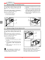
6.3. Cleaning of the heating plate
Follow the instructions below.
Remove the pan support of the gas
stove burners (A).
Remove the flame distributor B.
Thoroughly clean the burner body (C) and
flame distributor (B).
Thoroughly clean the recess D with use of
soft cloth and neutral cleaning agent.
Thoroughly dry the cleaned surfaces and
replace all elements.
Protect the interior of the gas
stove burner against water and dirt, to
avoid malfunction and clogging of
nozzles.
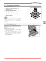
6.4. Cleaning of the oven
When the oven is cold remove bottom and grills.
After cleaning switch the empty oven on to avoid
corrosion.
Follow the instructions below:
Remove the oven bottom (A) and grill (B) and
clean them thoroughly.
Clean the oven interior from any burnt
residuals which may disturb correct operation.
Thoroughly dry the cleaned surfaces and
replace all elements.
B
A
ID
07
A
B
C
D
ID 06

10
ENGLISH
GB
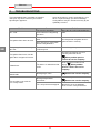
7. TROUBLESHOOTING
The information below is provided to recognize
and repair any failures that may occur when
operating the appliance.
Some of the failures can be repaired by the user,
others require thorough specialist knowledge.
Such problems may be solved exclusively by the
qualified personnel.
Problem Cause Solution
Gas smell.
The smell is sometimes
released when extinguishing
the flame.
Close the gas valve and ventilate the
room.
The ignition flame does not start.
The spark ignition does not
work.
Check operation of ignition devices.
Ignite the flame manually.
Air in the pipes in connection
with the long downtime.
The igniting flame continuously
goes out.
The thermal element is not
sufficiently hot.
Extend the ignition process.
The ignition flame burns, but the
igniter does not ignite the burner.
Check the thermostat. Inspect a
relevant protection device.
When problem persists
contact the service company
Yellow flame.
The burner is contaminated or
moist.
Clean the burner and leave for
drying.
When problem
persists contact the service
company.
It is difficult to rotate the burner
control knob.
Damaged gas valve.
Contact the service company.
The oven does not reach the
preset temperature.
Damaged operational
thermostat.
Replace the part.
Contact the service company.
The safety thermostat tripped.
Wait for the oven to cool down.
Then reset the safety thermostat.

11
ENGLISH
GB
8. INSTALLATION
8.1. Packaging and unpacking
During unloading and when installing the
appliance follow the information from the
manufacturer placed directly on the packaging
and in this manual.
To lift and transport the product plan to use a fork
lift or stacker, and pay attention to even weight
distribution to avoid a risk of tilting of the
packaging (avoid excessive incline!).
While using the elevator pay
attention to the gas supply hoses and
position of feet.
The packaging consists of the carton packaging
and wooden pallet. There are symbols printed on
the carton packaging that according to the
international agreements inform about the
regulations to follow when loading and unloading,
transporting and storing the appliance.
When collecting the goods check if the packaging
is complete and has not been damaged during
transport.
Any damage should be immediately reported to
the shipping company.
Unpack the appliance as soon as possible to
check if the appliance is not damaged.
Do not use a sharp object to cut the carton box. It
may damage the stainless steel inside the box.
Remove the carton packaging from bottom to top.
When unpacked check if the appliance is
according to the order.
In case of any difference inform the sales agent
immediately.
Do not store the packaging
materials (nylon bags, polystyrene
foam, clips ...) in the reach of children!
Remove the protective PVC layer from the out
and inner surfaces. If possible, do not use any
metal tools.
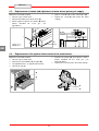
8.2. Installation (service technician)
All the stages of the installation must be carefully
planned.
The location should be equipped with all supply
connections and production waste outlet. The
location should also be properly lit and comply
with all hygiene and sanitary requirements
according to the binding regulations.
The appliance should be installed with the
minimum 5 cm clearance from the wall, if the
wall is not resistant to the minimum temperature
of 150 °C.
The devices with the oven must be
installed at least 50 cm from the wall.
Locate the appliance in the horizontal position by
adjusting the single feet.
To ensure the correct operation
of the appliance, the appliance must
be installed and operated in the
thoroughly ventilated room only.
50
ID
08
5 cm
THIS
SIDE UP
CAUTION
GLASS
KEEP DRY

12
ENGLISH
GB
When the device is to be
installed near the walls, partitions,
kitchen cabinets, decorative elements,
etc., they must be made from non-
flammable materials or covered with
suitable non-flammable materials.
Internal installation of the gas supply and the rooms
in which the device is housed must comply with the
local regulations applicable in the country in which
the device is used (Regulation of 12th of July 1996
and UNI-CIG 87/23).
In order to ensure proper gas burning in the
burners the required volume of air, i.e. approx. 2
cubic meters per hour for every kW of installed
power, must be supplied.
8.3. Extraction of fumes
The fumes from the stove should be continuously
extracted with use of kitchen extraction hoods
connected to the extraction dusts or stacks, or
extracting directly outside. When no kitchen
extraction hood may be installed, use the fan for
direct extraction outside, connected in such way
that lock of suction fan interrupts the gas supply.
Installation of stoves of type “A” does not
envisage connection to the fume exhaust system,
but to the appropriate extraction hood which
removes the fumes outside.
8.4. Installation of the appliance in a line
To fix the appliance in a line (neighbouring) follow
the steps:
Dismantle the control panel, and remove the cast
iron frame from the chimney if necessary.
Apply the sealing tape (A) onto the joining sides.
Place the appliances next to each other and in a
horizontal position (by adjusting the feet).
Connect the appliances with the joining elements.
8.5. Gas connection (service technician)
The gas connection must be performed in
compliance with the applicable regulations.
Before connecting the device check the technical
data, type of gas, working pressure and flow rate
which are provided on the rating plate.
The installation is performed by connecting the
connection pipe of the device with a pipe of the
gas distribution network. The cut-off valve must be
installed on the connection to shut the gas supply
off if necessary.
A
A
B
C
C

13
ENGLISH
GB
If there are significant pressure differences in the
gas supply installation, it is recommended to
install a pressure regulator.
After the installation, check the gas connection for
tightness.
When looking for gas leaks do
not use the open flame!
8.6. Switching into different gas type (service technician)
The device has been checked by the
manufacturer for the type of gas shown on the
rating plate. If a different type of gas is used,
follow these guidelines.
1. Close the gas cut-off valve (A).
2. Replace the nozzles of gas burners (see
section 9.3).
3. Replace the nozzles of the ignition flames (see
section 9.4).
4. Set the minimum value on the burners gas
valves (see section 9.1).
5. Remove the sticker from the rating plate and
apply a new sticker which includes used gas
type (item 4 of the rating plate).
8.7. Inspection (service technician)
Before starting the device the installation check-
up should be run to evaluate the working
conditions of every single component and
recognize any errors.
To check the heating plate it is recommended to
perform the following inspections:
1. Open the gas valve and check the tightness of
connections;
2. Check correct ignition and combustion of gas
stove burners;
3. Check and adjust, if necessary, the gas
pressure and flow rate in Max and Min
positions (see section 9.1).
4. Check if the safety thermostat operates
properly.
5. Check gas lines for gas leaks.
9. SETTINGS (service technician)
Before setting the device switch
on all protection devices.
First of all, close the gas valve and
prevent access to the device, which in
case of activation may lead to
unexpected situations endangering the
safety and health of people.
ID 12
ID 12

14
ENGLISH
GB
9.1. Minimum setting of the hob burner valve
These settings are required only if the connected
gas type differs from the factory preset and
checked gas, after switching to the different gas
type.
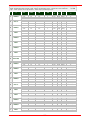
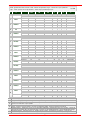
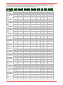
Before performing this setting check whether the
gas pressure is compliant with the value of nominal
pressure (see table in the appendices).
Follow the instructions below.
1. Close the gas cut-off valve.
2. Pull the control knob (A).
3. Unscrew screws B and remove the control
panel (C).
4. Slowly move the button from position (7)
clockwise to the minimum flow position (D)
(just before the blockade). Turn the screw
(D) counterclockwise in order to increase
the gas flow. After setting tighten the screw.
5. Finally reinstall the control panel (C) and
control knob (A).
9.2. Minimum setting of the oven burner valve
These settings are required only if the connected
gas type differs from the factory preset and
checked gas, after switching to the different gas
type.
Before performing this setting check whether the
gas pressure is compliant with the value of nominal
pressure (see table in the appendices).
Follow the instructions below.
1. Close the gas cut-off valve.
2. Pull the control knob (A).
3. Unscrew screws B and remove the control
panel (C).
4. Remove the injection nozzle D and replace
it with the one suitable for used gas type
(see appendices). After setting tighten the
screw.
5. Finally reinstall the control panel (C) and
control knob (A).
After completing all calibration and
settings, check the tightness of gas system
and proper operation of the device.
Make sure that the flame is stable with
minimum or maximum output pressure.
When the setting is done, install the prepared
seal and/or seal the adjustment screws.
C
A
B
D
D
C
A
B
ID
09
ID
13

15
ENGLISH
GB
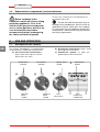
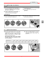
9.3. Replacement of nozzle and adjustment of gas stove burner primary air supply
Follow the instructions below.
Close the gas cut-off valve.
Remove the gas burners grates (A).
Remove the flame distributor (B) and
burner body (C).
Remove the recesses (D).
Loosen the screw E and set the Venturi pipe
(F).
When required, replace the nozzle (G) with a
nozzle intended for used gas (see
appendices).
Tighten the screw E and restore the initial
settings.
9.4. Replacement of the ignition flame nozzles of the gas stove burners
Follow the instructions below.
Close the gas cut-off valve.
Remove the gas burners grates (A).
Remove the flame distributors (B)
and burners bodies (C).
Remove the recesses (D).
Replace the gas burner ignition flame
nozzles (E).
Restore the initial settings.
E
B
C
A
D
H
E
F
B
C
A
D
G
ID 06
ID 15

16
ENGLISH
GB
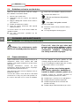
9.5. Replacement of nozzle and adjustment of oven burner primary air supply
Follow the instructions below.
Close the gas cut-off valve.
Remove the lower panel of the oven (A).
When required, replace the nozzle (B) with a
nozzle intended for used gas (see
appendices).
Loosen screw C and set the Venturi pipe (D).
Tighten the screw (C) and restore the initial
settings.
9.6. Replacement of the ignition flame nozzle of the oven burners
Follow the instructions below.
Close the gas cut-off valve.
Remove the oven bottom (A) and grill (B).
The ignition flame is assigned to the burner.
Loosen the nut (D).
Remove the nozzle (E) and replace it with a
nozzle intended for the used gas (see
attached tables).
Tighten the nut and restore the initial settings.
A
B
ID
07
D
E
H
A
B
C
D
GN
2/1

17
ENGLISH
GB
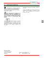
10. APPLIANCE DISPOSAL
The appliance is marked in conformity
with the European Directive 2002/96/EG
WASTE ELECTRICAL AND ELECTRONIC
EQUIPMENT (WEEE).
By disposing the appliance in
accordance with the regulations the
user contributes towards prevention of
adverse effects on environment and
health.
The symbol on the product or attached
manual indicates that the product cannot be
considered as ordinary household waste and
should be transferred to a special collection point
for electrical and electronic appliances for
recycling.
Local waste management regulations should be
observed.
Further information on procedure, reusing and
recycling of the product is available in local
offices, waste management unit or with the
product sales agent.
Bartscher GmbH
Franz-Kleine-Str. 28
D-33154 Salzkotten phone: +49 (0) 5258 971-0
Germany fax: +49 (0) 5258 971-120

I
ANLAGEN
ATTACHMENTS
ANNEXES
ALLEGATI
ANEXOS
ANEXOS
BIJLAGEN
ZAŁĄCZNIKI
La pagina si sta caricando...
La pagina si sta caricando...
La pagina si sta caricando...
La pagina si sta caricando...
La pagina si sta caricando...
La pagina si sta caricando...
La pagina si sta caricando...
La pagina si sta caricando...
La pagina si sta caricando...
La pagina si sta caricando...
La pagina si sta caricando...
La pagina si sta caricando...
La pagina si sta caricando...
La pagina si sta caricando...
La pagina si sta caricando...
La pagina si sta caricando...
La pagina si sta caricando...
-
 1
1
-
 2
2
-
 3
3
-
 4
4
-
 5
5
-
 6
6
-
 7
7
-
 8
8
-
 9
9
-
 10
10
-
 11
11
-
 12
12
-
 13
13
-
 14
14
-
 15
15
-
 16
16
-
 17
17
-
 18
18
-
 19
19
-
 20
20
-
 21
21
-
 22
22
-
 23
23
-
 24
24
-
 25
25
-
 26
26
-
 27
27
-
 28
28
-
 29
29
-
 30
30
-
 31
31
-
 32
32
-
 33
33
-
 34
34
-
 35
35
-
 36
36
-
 37
37


Bartscher 2951131 Istruzioni per l'uso
- Tipo
- Istruzioni per l'uso
in altre lingue
Documenti correlati
-
Bartscher 2952271 Istruzioni per l'uso
-
Bartscher 2952481 Istruzioni per l'uso
-
Bartscher 2955061 Istruzioni per l'uso
-
Bartscher 2959521 Istruzioni per l'uso
-
Bartscher 1519821 Istruzioni per l'uso
-
Bartscher 2954631 Istruzioni per l'uso
-
-
Bartscher 2953031 Istruzioni per l'uso
-
-
Bartscher 296215 Istruzioni per l'uso
Altri documenti
-
Bertazzoni MAS244GASXE DL 15eb39dd4158f4acf02d6ef7201e
-
Whirlpool A9GG1FC (X)/EX.1 Guida utente
-
-
-
Eurotech EDG-905IX Scheda dati
-
Hendi 225899 Manuale utente
-
Metos OPLG 80 Istruzioni per l'uso
-
Blodgett 951/966 Manuale del proprietario
-
ACV HM TC [V13] Technical Manual