La pagina si sta caricando...

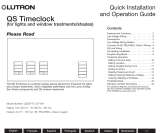
QS Timeclock
(for lights and window treatments/shades)
Installation and
Operation Guide
Please Read
The QS Timeclock is a premier energy-saving astronomic timeclock for lights
and window treatments, which integrates seamlessly with the Lutron Energi
Savr Node components and QS window treatments.
Model Number: QSGR-TC-3S-WH
Rating: 120 –240 V~ 50 / 60 Hz 100 mA
Output: 24 V- 150 mA IEC PELV/NEC® Class 2 supply
English
®
Français Español Português Deutsch Italiano Nederlands 中文
Contents
Features and Functions ..................2
Line Voltage Wiring .....................3
Terminations ..........................3
Line Voltage Wiring Details ...............4
Overview of IEC PELV/NEC® Class 2 Wiring ..5
QS Link Wiring ........................6
Completing Installation ..................8
Programming Mode ....................9
Associating QS Window Treatments .......10
Adjusting Window Treatment Settings .....10
Contact Closure Input (CCI) Setup ........13
Timeclock Operation
Setting Time and Date .................14
Setting Location .....................15
Setting Daylight Saving Time ...........15
Adding an Event .....................16
Deleting / Viewing an Event .............17
Setting / Viewing / Deleting a Holiday ......18
Copying / Deleting a Schedule ...........19
Afterhours ...........................20
Diagnostics ..........................21
Setting the Security Password ...........21
Language Selection ....................22
Faceplate Removal ....................22
Troubleshooting .......................23
Warranty, Contact Information ...........24

OK
12
3
4
5
6
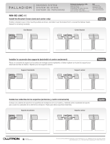
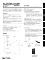
Info screen
Displays programming
functions
Program buttons
Shade (window treatment)
button groups
Preset and raise/lower
buttons with integral LEDs
(maximum of 3 button
groups)
Timeclock button
Displays current
timeclock info
OK button
Used for programming,
navigation
USB type mini B
For programming via PC
Features and Functions
QS Timeclock Installation and Operation Guide 2
®

QS Timeclock Installation and Operation Guide 3
®
D1 D1 D2 D2
• Pull power wiring from distribution panel to QS Timeclock.
• Each line voltage terminal can accept one 12 AWG (4.0 mm²) wire.
Line Voltage Wiring
D1 D1 D2 D2
NOT USED
Rear of
QS Timeclock
1234
12
ABC
123456LN
Line voltage (Line / Hot)
is labeled L.
100–240 V~ only
Distribution Panel
1234
12
ABC
123456LN
Terminations
QS Communication link
Contact closure input and 24 V- power
NOT
USED
Input Power
L: Line / Hot
N: Neutral
: Ground

Line Voltage Wiring Details
• Use properly certified cable for all line
voltage/mains cables.
• Proper short-circuit and overload
protection must be provided at the
distribution panel.
• Install in accordance with all local and
national electrical codes.
• IEC PELV/NEC® Class 2 terminals may
be temporarily unplugged for ease of
contact closure and control wiring.
• Notice: Risk of damage to unit. Do not
connect line voltage/mains cable to IEC
PELV/NEC® Class 2 terminals.
Step 1: Install wallbox. Mount a 3` in
(89 mm) deep 4-gang U.S. wallbox on a
dry, flat indoor surface that is accessible
and allows for system programming and
operation. Allow at least 4` in (110 mm)
clearance above and below the faceplate
to ensure proper heat dissipation. Allow
1 in (25 mm) for faceplate overhang on
all sides.
Note: 4-gang wallbox available from
Lutron; P/N 241400.
Step 2: Check wiring.
• Earth/ground terminal connection must
be made as shown in wiring diagrams
(see page 3).
• Follow all local and national electrical
codes when installing IEC PELV/NEC®
Class 2 wiring with line voltage/mains
wiring.
WARNING! Electric Shock hazard.
May result in Serious Injury or
Death. Always turn off circuit
breaker or remove main fuse from
power line before doing any work.
Step 3: Connect line voltage.
• Strip 9 in (8 mm) of
insulation off the line
voltage/mains cables in
the wallbox.
• Connect the line voltage/mains and
ground wires to the appropriate terminals
on the back of the timeclock.
L: Line / Hot
N: Neutral
: Ground
The recommended installation torque is
5.0 in∙lb (0.6 N∙m) for line voltage/mains
connections and 5.0 in∙lb (0.6 N∙m) for
the earth/ground connection.
Notice: Risk of damage to unit.
The QS Timeclock must be in stalled by
a qual i fied electrician in accordance with
all applica ble reg u la tions and building
codes. Im prop er wiring can result
in dam age to the timeclock or oth er
equipment.
QS Timeclock Installation and Operation Guide 4
®
Faceplate overhangs
wallbox on all sides;
allow 1 in (25 mm)
4` in
(110 mm)
9 in
(8 mm)

Contact Closure Input Wiring
24 V- 50 mA
For settings, see CCI Setup.
12
ABC
N H123456
1234
Note: Use appropriate wire
connecting devices as
specified by local codes.
Example:
Third-party contact
closure to enable /
disable timeclock
1: COM
2: 24 V-*
3: MUX
4: MUX
Control Wiring
24 V- 100 mA
Overview of IEC PELV/NEC® Class 2 Wiring
18 AWG (1.0 mm
2
)
each terminal
A: CCI SIG
B: 24 V-
C: CCI COM
To other
QS devices
Data (terminals 3 and 4):
Twisted, shielded pair 22 AWG (0.5 mm
2
) each terminal
Common and power (terminals 1 and 2):
Two 18 AWG (1.0 mm
2
) each terminal (for link <500 ft/153 m)
Two 12 AWG (4.0 mm
2
) each terminal (for link 500–2000 ft/153–610 m)
* Do not connect terminal 2
between a QS Timeclock
and any other power supply.
QS Timeclock Installation and Operation Guide 5
®
IEC PELV/NEC® Class 2 control wiring
(2) 18 AWG (1.0 mm
2
)
1: Common
2: 24 V-
Wiring Detail
For links 500–2000 ft (153–610 m)
4
3
2
1
Data link: (1) twisted, shielded pair
22 AWG (0.5 mm
2
)
3: MUX
4: MUX
(2) 12 AWG
(4.0 mm
2
)
(2) 12 AWG
(4.0 mm
2
)
NOT
USED

QS Timeclock Installation and Operation Guide 6
®
• Each IEC PELV/NEC® Class 2 terminal
accepts up to two 18 AWG (1.0 mm²)
wires.
• Connect the terminal 1, 3, and 4
connections to all control units,
wallstations, and control interfaces.
• Total length of control link must not
exceed 2000 ft (610 m).
• Do not allow IEC PELV/NEC® Class 2
wires to contact line/mains wires.
• The QS Timeclock provides 3 PDUs
(Power Draw Units) on the QS Link.
For more information, see Lutron
P/N 369405, “Power Draw Units on the
QS Link” at www.lutron.com
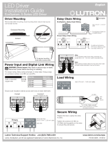
QS Communication Link
Terminal Detail
QS Link Wiring
D1 D1 D2 D2
_
MUX
24 V-
COM
LUTRON
LUTRON LUTRON LUTRON
Energi Savr Node
Sivoia QS
smart
power
panel
Sivoia QS
shade
Sivoia QS
shade
QS Timeclock
Wallstation
Wallstations
Connect all 4
terminals within a
power group:
1: Common
2: 24 V-
3 and 4: Data
Connect only 3
terminals between
power groups:
1: Common
3 and 4: Data
Do not connect
Terminal 2: 24 V-
A
B
A
A
A
B
B
B
Power Group 1
Power Group 2
Power Group 3
Power Group 4
Energi Savr Node
Wiring Example

• System communication uses
IEC PELV/NEC® Class 2 wiring.
• Follow all local and national electrical
codes when installing IEC PELV/NEC®
Class 2 wiring with line voltage/
mains wiring.
• Make all connections in the control
unit’s wallbox.
• Wiring can be T-tapped or daisy-chained.
• 24 V- 100 mA IEC PELV/NEC® Class 2.
QS Link Wiring (continued)
QS Timeclock Installation and Operation Guide 7
®
T-Tap Wiring Example
LUTRON LUTRONLUTRON LUTRON
LUTRON LUTRON LUTRON
LUTRON
LUTRON
L
U
TRON
LUTRON LUTRON LUTRON
QS Timeclock
seeTouch QS
Sivoia QS
Shade
Sivoia QS
smart panel
Energi Savr Node
Energi Savr Node
LUTRON LUTRONLUTRON LUTRON
LUTRON LUTRON LUTRON
LUTRON
LUTRON
L
U
TRON
LUTRON LUTRON LUTRON
Sivoia QS
smart panel
QS Timeclock
Sivoia QS
Shade
seeTouch QS
Daisy-Chain Wiring Example
Energi Savr Node
Energi Savr Node
Note: The QS Timeclock provides
3 power draw units on the QS link.
For more information on PDUs, see
“Power Draw Units on the QS Link”,
PN 369405 at www.lutron.com
Wire Sizes (check compatibility in your area)
QS Link Wiring Length Wire Gauge Lutron Cable Part Number
Less than 500 ft (153 m) Power (terminals 1 and 2)
1 pair 18 AWG (1.0 mm
2
) GRX-CBL-346S (non-plenum)
GRX-PCBL-346S (plenum)
Data (terminals 3 and 4)
1 twisted, shielded pair 22 AWG (0.5 mm
2
)
500 to 2000 ft
(153 to 610 m)
Power (terminals 1 and 2)
1 pair 12 AWG (4.0 mm
2
) GRX-CBL-46L (non-plenum)
GRX-PCBL-46L (plenum)
Data (terminals 3 and 4)
1 twisted, shielded pair 22 AWG (0.5 mm
2
)

Completing Installation
1. Mount the QS Timeclock in the wallbox
as shown using the four screws pro vid ed.
Note: Follow all local and national
electrical codes when installing IEC PELV/
NEC® Class 2 wiring with line voltage/
mains wiring.
2. Verify installation.
3. Restore power.
4. Apply the protective overlay to the QS
Timeclock.
QS Timeclock Installation and Operation Guide 8
Note: When tightening mounting
screws, make sure that the hinged
cover and faceplate will open fully,
as shown.
Wall
7.9 in
(200 mm)
3.5 in
(87 mm)
3.75 in
(95 mm)
Protective overlay
(apply after installation)
Faceplate
(apply after installation)
®

Entering and Exiting Programming Mode
To enter programming mode:
Press and hold the top and bottom
programming buttons simultaneously for
3 seconds. The LEDs in the scene buttons
will scroll from top to bottom, confirming
that you are in programming mode, and the
info screen will display the main menu.
To exit programming mode:
Press and hold the top and bottom
programming buttons simultaneously for
3 seconds.
Navigating Menus in Programming Mode
Master Buttons
The Master buttons allow you to move through the menu
choices. The current choice is highlighted on the info screen.
OK Button
The OK button chooses the current highlighted menu choice.
This will either take you to the next menu or accept a setting you
have selected. When the screen displays a Yes / No question, the
OK button is “Yes”.
Timeclock Button
The timeclock button functions as a “back” button during
programming mode. Pressing the timeclock button takes you
back one step in the current menu. Pressing it repeatedly
will eventually return you to the main menu, but will not exit
programming mode. When the screen displays a Yes / No
question, the Timeclock button is “No”.
Programming Mode
Main menu
CCI setup
Timeclock
QS Timeclock Installation and Operation Guide 9
®
OK
12
3
4
5
6
Press and hold the top
and bottom buttons for
3 seconds to enter or exit
programming mode
Master buttons
OK button
Timeclock (back) button

QS Timeclock Installation and Operation Guide 10
®
To associate or disassociate window treatments with a
shade button group:
1. On the QS Timeclock shade button group you wish to assign
window treatments to, enter window treatment programming
mode: Press and hold the top (open) and bottom (close)
buttons simultaneously for 3 seconds. The top and bottom
LEDs will flash.
Window Treatments that are unassigned will move to open
(up), and window treatments that are assigned will move to
close (down).
2. Tap the top (open) button to start assigning.
3. Tap the top (open) button repeatedly to cycle forward
through the addresses; tap the bottom (close) button to cycle
backward.
4. Press the window treatment group lower button to associate
the window treatment.
Press the window treatment group raise button to
disassociate the window treatment.
5. Exit window treatment programming mode: Press and hold
the top (open) and bottom (close) buttons simultaneously for
3 seconds. The top and bottom LEDs will stop flashing.
You can associate the shade button groups on the QS
Timeclock with QS window treatments so the shade buttons
can directly control the window treatments.
Associating QS Window Treatments
Press and hold the
top (open) and bottom
(close) buttons on the
QS Timeclock shade
button group to enter or
exit window treatment
programming mode.
OK
1 2 3 4 5 6
Open
Preset
Close
Lower button: Press to
associate
Raise button: Press to
disassociate
Adjusting Window Treatment Settings
Setting Limits
Note: Entering Limit Setup mode may cause window treatments
to move approximately 8 in (200 mm) up or down. Be sure that
each window treatment is positioned so that the fabric can
safely move 8 in (200 mm) up or down before entering Limit
Setup mode.
1. On any shade button group, press and hold
simultaneously the top and raise buttons. The
LEDs next to the top and bottom buttons will
cycle.
At any time while in Limit Setup mode, you
can move all window treatments together to
their current open limit by double-tapping the
top button, or to their current close limit by
double-tapping the bottom button.
Note: Window treatment electronic drive units (EDUs) must first
be associated to a shade button group before its limits
can be adjusted.
2. Select the EDU you want to adjust using the top button on the
shade button group. Each time you press and release the top
button, a different EDU that is assigned to that shade button
group will open and close in an 8 in (200 mm) range to indicate
it is selected.
Tap the top button until the EDU for the window treatment you
wish to adjust moves. (You can also use the bottom button,
which moves through the assigned EDUs in the opposite order.)
3. Adjust the currently selected EDU to the desired
level for the open limit (the maximum the window
treatment is allowed to open) using the raise and
lower buttons.
4. Press and hold the top button on the shade button group for
5 seconds to store the current position as the open limit. The
LED next to the top button will flash quickly for 2 seconds.
(continued)
OK
12
3
4
5
6

QS Timeclock Installation and Operation Guide 11
®
Setting Limits (continued)
5. Adjust the currently selected EDU to the desired level for the
close limit (the maximum the window treatment is allowed to
close) using the raise and lower buttons.
6. Press and hold the bottom button on the shade button group
for 5 seconds to store the current position as the close limit.
The LED next to the bottom button will flash quickly for
2 seconds.
7. Repeat steps 2 through 6 to set the open and close limits for
each window treatment assigned to the shade button group.
8. Press and hold simultaneously the top and raise buttons on
the shade button group to exit Limit Setup mode.
Preset Adjustment: Simple Method
1. Use the raise and lower buttons on the shade
button group to set all electronic drive units
(EDUs) of the window treatments to the desired
preset levels.
2. Press and hold the middle button on the
shade button group for 5 seconds to
save the EDU preset positions. The LED
next to the button will flash and then light
continuously, indicating the preset has been
stored.
Note: Once EDU presets have been
assigned to buttons on a shade
button group, those presets are
accessible for an EDU only using the shade button
group it is assigned to, and a shade button group can
access preset levels only for those EDUs assigned to it.
Adjusting Window Treatment Settings (continued)
OK
12
3
4
5
6
Preset Adjustment: Advanced Method
• The advanced method for adjusting presets is needed only if
you wish to have the window treatments assigned to the shade
button group set at different positions in the preset. If, however,
you wish all the window treatments in the group to be lined
up with one another in the preset, you should use the Simple
Method at left.
• Entering Assignment mode will cause the window treatments to
move between their open and close limits. Verify that the open
and close limits have been set correctly.
1. On the shade button group whose preset you
wish to adjust, press and hold simultaneously
the top and bottom buttons. The LEDs
next to the buttons will flash. EDUs for the
assigned window treatments will move to
their closed limits, and EDUs for unassigned
window treatments will move to their open
limits.
2. Press and release the middle button on that
shade button group. The adjacent LED will blink rapidly. EDUs
for assigned window treatments will automatically move to their
current preset settings.
3. Use the raise and lower buttons to move all EDUs
for assigned window treatments together to the
desired preset setting.
4. To move an EDU individually to its desired preset setting, select
the EDU using the top button on the shade button group. Each
time you press and release the top button, a different EDU that
is assigned to that shade button group will open and close in
an 8 in (200 mm) range. Press repeatedly until the EDU for the
window treatment you wish to adjust moves. Adjust that EDU to
the desired height using the raise and lower buttons.
Repeat this step for all assigned EDUs.
5. Once you are satisfied that all the assigned EDUs are set to the
positions you want to assign as the preset, press and hold the
middle button on the shade button group for 5 seconds. The
preset will be saved.
6. Press and hold simultaneously the top and bottom buttons on
the shade button group for 5 seconds to exit to normal mode.
The LEDs next to the buttons will stop flashing.
OK
12
3
4
5
6

QS Timeclock Installation and Operation Guide 12
®
Adjusting Window Treatment Settings (continued)
Naming a Group of Window Treatments (Shades)
1. Enter programming mode.
2. Use the Master buttons to highlight
“Shade Labels” and press the OK button
to accept.
3. Use the Master buttons to highlight your
desired shade group. Press the OK button
to accept.
4. Use the Master buttons to highlight
“Custom” and press the OK button to
accept.
5. Use the Master buttons to scroll through
the characters (lowercase and uppercase
letters, plus numbers 0 through 9). The
character you are currently changing will
be underlined on the screen. Press OK to
select the character you want, then repeat
for all available characters. Choose a
space (no character) and press OK for any
remaining characters. Press the OK button
to accept.
6. The info screen will confirm that your
name has been saved.
7. Exit programming mode.
Main menu
CCI setup
Shade Labels
Select group
Shade Grp 1
Label shade grp
Custom
Label shade grp 1
1: A
1 / 11
A
Saved
OK
1 2 3 4 5 6
Master
buttons
OK
button
Timeclock
(back) button

QS Timeclock Installation and Operation Guide 13
®
Contact Closure Input (CCI) Setup
The integral contact closure input (CCI) on the back of the
QS Timeclock can be configured as:
Afterhours: Allows the CCI to start and end Afterhours.
Timeclock: Allows the CCI to enable and disable the
timeclock.
Disable CCI: The CCI will have no effect on the system.
Changing the operation of the contact closure input:
1. Enter programming mode.
2. Use the Master buttons to highlight
“CCI Setup” and press the OK button
to accept.
3. Use the Master buttons to highlight
“CCI Mode” and press the OK button
to accept.
4. Use the Master buttons to highlight
the mode you wish the CCI to control.
Press the OK button to accept.
5. The info screen will confirm that your
setting has been saved.
6. Exit programming mode.
CCI Mode
Afterhours
Saved
Saved
Main menu
Timeclock
CCI menu
CCI Type
CCI Setup
CCI Mode
OK
1 2 3 4 5 6
Master
buttons
OK
button
Timeclock
(back) button
The integral contact closure input (CCI) on the back of the
QS Timeclock is compatible with either type of contact
closure device:
Maintained (default): The QS Timeclock will act on both a contact
closure and a contact open / release event.
Example: CCI Mode set to Afterhours. Contact closure starts
Afterhours. Contact open / release ends Afterhours.
Momentary: The GRAFIK Eye QS control unit will act on only
contact closure events.
Example: CCI Mode set to Afterhours. Contact closure starts
Afterhours. Contact open/release has no effect. Second contact
closure ends Afterhours.
Changing the type of contact closure input:
1. Enter programming mode.
2. Use the Master buttons to highlight “CCI
Setup” and press the OK button to accept.
3. Use the Master buttons to highlight “CCI
Type” and press the OK button to accept.
4. Use the Master buttons to highlight the
type you wish the CCI to control. Press
the OK button to accept.
5. The info screen will confirm that your
setting has been saved.
6. Exit programming mode.
CCI Type
Maintained
Saved
Saved
CCI menu
CCI Mode
CCI Type

QS Timeclock Installation and Operation Guide 14
®
Timeclock Operation
Setting Time and Date
1. Enter programming mode.
2. Use the Master buttons to highlight “Timeclock” and press the
OK button to accept.
3. Use the Master buttons to highlight “Time & date” and press
the OK button to accept.
4. Use the Master buttons to highlight either “12 Hr” or “24 Hr”
format for time display and press the OK button to accept.
5. Use the Master buttons to highlight the current hour and press
the OK button to accept. Repeat for the current minutes.
6. Use the Master buttons to highlight the current year and press
the OK button to accept. Repeat for the current month and
date.
7. The info screen will confirm that your time and date have
been saved.
8. Exit programming mode.
Main menu
Timeclock
Scene setup
Timeclock
End afterhours
Time & date
Set time
: 00 AM
08
Timeclock
Set date
: 00
2009
Set date
Set format
12 Hr
March
Set date
17
Set time
08 : AM
30
Saved
OK
1 2 3 4 5 6
Master
buttons
OK
button
Timeclock
(back) button

QS Timeclock Installation and Operation Guide 15
®
Setting Daylight Saving Time
1. Enter programming mode and
select “Timeclock”. Use the Master
buttons to highlight “Set DST” and
press the OK button to accept.
2. Use the Master buttons to highlight
“YES” if your location observes
daylight saving time, or “NO” if it
does not. Press the OK button to
accept.
3. If yes, use the Master buttons to
choose either “USA 2007” (the
second Sunday in March to the first
Sunday in November), or “Other.”
For “Other,” follow the screens to
set start and end dates and amount
of time.
4. Press the OK button to accept. The
info screen will confirm that your
time and date have been saved.
5. Exit programming mode.
Timeclock Operation (continued)
Setting Location
1. Enter programming mode.
2. Use the Master buttons to highlight
“Timeclock” and press the OK button to
accept.
3. Use the Master buttons to highlight
“Location” and press the OK button to
accept.
4. Use the Master buttons to set your
location by either country and city
or latitude and longitude. Press the
OK button to accept.
5. Use the Master buttons to highlight
the country and press the OK button
to accept. Repeat for the state and
closest city.
6. The info screen will confirm that your
time and date have been saved.
7. Exit programming mode.
Main menu
Timeclock
Scene setup
Timeclock
Time & date
Location
Location by
Lat/Longitude
Country, City
Timeclock
State
Pennsylvania
City
Philadelphia
Country
08 : 00
USA
Timeclock
Location
Set DST
DST
: 00
Yes
Saved
OK
1 2 3 4 5 6
Master
buttons
OK
button
Timeclock
(back) button

QS Timeclock Installation and Operation Guide 16
®
Timeclock Operation (continued)
Adding an Event
1. Enter programming mode.
2. Use the Master buttons to highlight “Timeclock” and press the OK
button to accept.
3. Use the Master buttons to highlight “Add events” and press the
OK button to accept.
4. Use the Master buttons to highlight the recurrence for this event:
day of the week, holiday, weekdays or weekends. Press the OK
button to accept.
5. Use the Master buttons to highlight the type of the event (fixed time of day or a relative time to sunrise or
sunset). Press the OK button to accept.
6. For a fixed-time event, use the Master buttons to highlight the hour for your event to begin; press the OK
button to accept. Repeat for the minutes.
For a relative-time event, use the Master buttons and the OK button to set the hour, then the minutes relative
to sunrise or sunset (maximum of 1 hour, 59 minutes before or after sunrise or sunset).
7. Use the Master buttons to highlight the desired action for the timeclock event:
• Scenes 1-16, Off
• Window Treatment Groups 1-3 open, preset, or close
• Start/End Afterhours
8. The info screen will confirm that your event has been saved.
9. Repeat steps 4 through 9 for additional events.
10. Exit programming mode.
Main menu
Timeclock
Scene setup
Timeclock
Add events
Monday
Add events
Time of day
Add events
Scene
Scene 1
Set time
: 00 AM
08
Saved
Timeclock
View events
Add events
OK
1 2 3 4 5 6
Master
buttons
OK
button
Timeclock
(back) button

QS Timeclock Installation and Operation Guide 17
®
Timeclock Operation (continued)
Deleting an Event
1. Enter programming mode.
2. Use the Master buttons to highlight
“Timeclock” and press the OK button to
accept.
3. Use the Master buttons to highlight
“Delete events” and press the OK button
to accept.
4. Use the Master buttons to highlight the
day of the week (or holiday) when the
event occurs; press the OK button to
accept.
5. Use the Master buttons to highlight the
event to delete; press the OK button to
accept.
6. A screen will appear, verifying you wish to
delete the event. Press the OK button to
accept and delete; otherwise, press the
timeclock button to go back.
7. The info screen will confirm that your
event has been deleted.
8. Exit programming mode.
Main menu
Timeclock
Scene setup
Timeclock
Copy schedule
Timeclock
Delete?
Delete
8:00 AM
Scene 5
Delete
Monday
01/03
Viewing an Event
1. Enter programming mode, select
“Timeclock,” and select “View events”.
2. Use the Master buttons to highlight the
day of the week (or holiday) when the
event occurs; press the OK button to
accept.
3. Use the Master buttons to highlight the
event to view; press the OK button to
accept.
4. Press the OK button to return to the
Timeclock menu.
5. Exit programming mode.
Timeclock
Delete events
Add events
View events
Monday
View
8:00 AM
Scene 5
View events
Monday
1/3
R
Delete events
Deleted
OK
12
3
4
5
6910
11 12
13
14
7
815
16
9-16
1-8
Master
buttons
OK
button
Timeclock
(back) button

QS Timeclock Installation and Operation Guide 18
®
Timeclock Operation (continued)
Setting a Holiday
1. Enter programming mode.
2. Use the Master buttons to highlight
“Timeclock” and press the OK button
to accept.
3. Use the Master buttons to highlight
“Holiday” and press the OK button to
accept.
4. Use the Master buttons to highlight
“Set holiday” and press the OK button
to accept.
5. Use the Master buttons to highlight
the month of the holiday and press the
OK button to accept. Repeat for the
date.
6. The info screen will confirm that your
holiday has been set.
7. Exit programming mode.
Note: The QS Timeclock supports up
to 25 unique holidays. Follow the
steps in “Adding an Event” to
add Holiday timeclock events.
Timeclock
Delete schedule
Holiday
Add event
View holiday
Set holiday
Holiday
Set holiday
1/25
1
Feb
Monday
Set holiday
1/25
Feb
14
Deleting a Holiday
1. Enter programming mode, select
“Timeclock,” select “Holiday,” and
select “Delete holiday”.
2. Use the Master buttons to highlight the
holiday you wish to delete (or delete all
holidays) and press the OK button to
accept.
3. Press the OK button to delete the
selected holiday. The info screen
will confirm that your holiday has
been deleted.
4. Exit programming mode.
Holiday
View holiday
Delete holiday
Monday
Saved
Deleted
Viewing a Holiday
1. Enter programming mode, select
“Timeclock,” select “Holiday,” and select
“View holiday”.
2. Use the Master buttons to scroll through
the dates of the programmed holidays.
3. If no holidays are programmed, the
info screen will display a screen
informing you.
4. Exit programming mode.
View Holiday
1/25
Feb 14
Monday
No Holidays
OR
Delete holiday
1/2
Feb 14
Delete holiday
1/2
Delete?
OK
1 2 3 4 5 6
Master
buttons
OK
button
Timeclock
(back) button

QS Timeclock Installation and Operation Guide 19
®
Timeclock Operation (continued)
Copying a Schedule
1. Enter programming mode.
2. Use the Master buttons to highlight
“Timeclock” and press the OK button
to accept.
3. Use the Master buttons to highlight
“Copy Schedule” and press the
OK button to accept.
4. Use the Master buttons to highlight the
day you want to copy the schedule from
and press the OK button to accept.
5. Use the Master buttons to highlight the
day you want to copy the schedule to
and press the OK button to accept.
6. The info screen will ask you to confirm
overwriting all events occurring on the
selected day to copy to; press the OK
button to accept.
7. Exit programming mode.
Timeclock
Delete schedule
Delete events
Copy schedule
Copy from
Monday
Monday
Timeclock
Overwrite
all events?
Deleting a Schedule
1. Enter programming mode,
select “Timeclock,” and select
“Delete schedule”.
2. Use the Master buttons to highlight the
day of the schedule you wish to delete
and press the OK button to accept.
3. The info screen will confirm that your
event has been deleted.
4. The info screen will ask you to confirm
deleting the schedule on the selected
day; press the OK button to accept.
5. Exit programming mode.
Timeclock
Delete events
Delete schedule
Saved
Delete
Sunday
schedule?
Monday
Copy to
Tuesday
Monday
Delete schedule
Sunday
OK
1 2 3 4 5 6
Master
buttons
OK
button
Timeclock
(back) button

QS Timeclock Installation and Operation Guide 20
®
Afterhours
The Afterhours feature of the QS
Timeclock can be used to automatically
set lights to an energy-saving level
(typically “Scene Off”). This feature allows
occupants to manually turn on lights, but
will automatically turn them off after a
specified amount of time.
When Afterhours starts, the lights will
flash to alert occupants that the lights
will soon fade to the Afterhours Scene.
Occupants then can press a keypad
button to extend the time until the
Afterhours feature flashes the lights again.
Note: The Afterhours feature must
be programmed to start or end
through Timeclock events or the
integral contact closure input.
The QS Timeclock will activate this
feature only if the Afterhours mode
has been set to “Enabled”.
Afterhours Settings
Flash count: The amount of times the
lights will flash to alert the room that the
Afterhours Scene will soon be activated.
Delay time: The amount of time after
the end of the “Flash count” before the
Afterhours Scene is activated.
Warn time: The amount of time the
system will wait after the Afterhours
Scene is interrupted before flashing the
lights again and restarting the Delay Time
countdown.
Programming the Afterhours Feature
1. Enable afterhours on QS Timeclock.
2. Add one or more events on the
QS Timeclock that will start or end the
afterhours feature. Alternatively, the
integral CCI can be set up to start and
end Afterhours.
3. Refer to the instructions for your
Energi Savr Node unit to program the
afterhours settings.
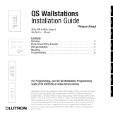
Afterhours Examples
Afterhours starts;
Lights flash
Delay time
Button press:
Office worker
Button press:
Security guard
Delay time
(lights
flash)
Delay time
(lights
flash)
Warn Time Warn TimeDelay time
Afterhours Scene
Afterhours Scene Afterhours
Scene
Example 1: Typical Office
Example 2: Late Night/Security Check
Afterhours ends
1/192