
VE1801EUT HDMI HDBaseT Lite Transmitter with EU Wall Plate
www.aten.com
www.aten.com
www.aten.com
A
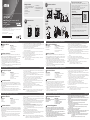
Hardware Review
Front View
1. Power LED
2. Link LED
3. HDMI In
A
Hardware Review
B
Hardware Installation
© Copyright 2018 ATEN
®
International Co., Ltd.
ATEN and the ATEN logo are trademarks of ATEN International Co., Ltd. All rights reserved. All
other trademarks are the property of their respective owners.
This product is RoHS compliant.
Part No.PAPE-1223-P20G Printing Date: 09/2018
HDMI HDBaseT Lite Transmitter with EU
Wall Plate
Quick Start Guide
VE1801EUT
ATEN VanCryst
™
Support and Documentation Notice
All information, documentation, fi rmware, software utilities, and
specifi cations contained in this package are subject to change without
prior notifi cation bythe manufacturer.
To reduce the environmental impact of our products, ATEN
documentation and software can be found online at
http://www.aten.com/download/
Technical Support
www.aten.com/support
이 기기는 업무용(A급) 전자파적합기기로서 판매자 또는 사용자는 이 점을 주의하시기 바라며,
가정외의 지역에서 사용하는 것을 목적으로 합니다.
EMC Information
FEDERAL COMMUNICATIONS COMMISSION INTERFERENCE
STATEMENT:
This equipment has been tested and found to comply with the
limits for a Class A digital device, pursuant to Part 15 of the
FCC Rules. These limits are designed to provide reasonable
protection against harmful interference when the equipment
is operated in a commercial environment. This equipment
generates, uses, and can radiate radio frequency energy and,
if not installed and used in accordance with the instruction manual, may cause harmful interference
to radio communications. Operation of this equipment in a residential area is likely to cause harmful
interference in which case the user will be required to correct the interference at his own expense.
FCC Caution: Any changes or modifi cations not expressly approved by the party responsible for
compliance could void the user's authority to operate this equipment.
Warning: Operation of this equipment in a residential environment could cause radio interference.
Suggestion: Shielded twisted pair (STP) cables must be used with the unit to ensure compliance with
FCC & CE standards.
This device complies with Part 15 of the FCC Rules. Operation is subject to the following two
conditions:(1) this device mat not cause harmful interference, and(2) this device must accept any
interference received, including interference that may cause undesired operation.
Scan for
more information
Package Contents
1 VE1801EUT HDMI HDBaseT Lite
Transmitter with EU Wall Plate
4 Foot Pads
1 Faceplate
2 Pan Head Screws
4 PF Screws
3
2
1
4
3
2
5
1
3
2
8
HDMI Source Device
6
5
HDMI Display
6
Touch
Screen
Power
Cable
9
4
PC
2-Pin
Teminal
Block
+5V
GND
5mm
7a
(+)
(-)
+5V
7b
7c
WALL
10
Power Supply
Information
Front View Rear View
VE1801EUT (Front View) VE1801EUT (Rear View)
1 Power Adapter
1 RS-232 Terminal Block (3-pin)
1 Power Terminal Block (2-pin)
1 User Instructions
VE802R (Front)
(Recommended)
VE802R (Rear)
(Recommended)
Rear View
1. Firmware Upgrade Switch
2. HDBaseT Out
3. Power Terminal Block
4. RS-232 Terminal Block
5. Grounding Terminal
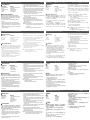
B
Hardware Installation
Follow the steps below to safely install the VE1801EUT. The procedure below
assumes connection with the ATEN VE802R. For an up-to-date list of compatible
ATEN video extenders, please visit the VE1801EUT web page.
1. Prepare a mounting site with proper dimensions to accommodate the VE1801EUT.
Refer to the CAD drawing from the product web page for the dimensions.
2. Ground the VE1801EUT by connecting one end of a grounding wire to the unit’s
grounding terminal, and the other end to a suitable grounded object.
1
3. Connect the VE1801EUT’s HDMI In port to the source device’s HDMI Out port using
an HDMI cable.
4. Connect the VE1801EUT’s HDBaseT Out port to the VE80
2
R’s HDBaseT In port using
a Cat 5e/6 cable or an ATEN 2L-2910 cat6 cable.
5. Connect the VE80
2
R’s HDMI Out port to a display device using an HDMI cable.
6. (Optional) Connect a controller or a PC to the VE1801EUT's RS-232 Terminal Block, and a
touch screen or a bar code scanner to the VE802R's RS-232 Terminal Block.
7. Follow the steps below to prepare the VE1801EUT’s power cable.
(a) Cut the connector end of the power adapter.
(b) Strip 5 mm (0.5 cm) off the insulation cover of the Power Adapter Cable to expose the
+5V wire and the GND wire.
2
(c) Insert the +5V wire and the GND wire tightly into the provided 2-pin terminal block.
8. Plug the power terminal block to the VE1801EUT.
9. Plug the power cable to the VE80
2
R’s Power Jack.
10. Secure the faceplate to the VE1801EUT with the four PF screws, and then secure the
assembly to the wall with the two Pan Head screws.
11. Power on all the connected devices.
Note: 1. Do not omit this step. Proper grounding helps prevent damage to the unit from
surges or static electricity.
2. To test the wire polarity, use a voltmeter.
Émetteur HDMI HDBaseT Lite VE1801EUT avec plaque murale UE
www.aten.com
A
Description de l’appareil
Vue avant
1. LED d'alimentation
2. Diode de lien
3. Entrée HDMI
Vue arrière
1. Commutateur de mise à niveau du
microprogramme
2. Sortie HDBaseT
3. Connecteur bornier d'alimentation
4. Bornier RS-232
5. Borne de mise à la terre
B
Installation matérielle
Suivez les étapes ci-dessous pour installer le VE1801EUT en toute sécurité. La
procédure ci-dessous suppose une connexion avec l'ATEN VE802R. Pour obtenir
une liste à jour des systèmes d'extension vidéo ATEN compatibles, visitez la page
Web du VE1801EUT.
1. Préparez un site de montage aux dimensions appropriées pour accueillir le
VE1801EUT.
Reportez-vous au dessin CAO de la page Web du produit pour les dimensions.
2. Reliez le VE1801EUT à la terre en connectant une extrémité du fi l de terre à la borne
de mise à la terre de l'unité et l'autre extrémité à un objet relié à la terre.
1
3. Connectez le port d'entrée HDMI du VE1801EUT au port de sortie HDMI du périphérique
source à l'aide d'un câble HDMI.
4. Connectez le port de sortie HDBaseT du VE1801EUT au port d'entrée HDBaseT du VE80
2
R
à l'aide d'un câble Cat 5e/6 ou d'un câble ATEN 2L-2910 cat6.
5. Connectez le port de sortie HDMI du VE802R à un périphérique d'affi chage à l'aide d'un
câble HDMI.
6. (Optionnel) Connectez un contrôleur ou un PC au bornier RS-232 du VE1801EUT et un
écran tactile ou un lecteur de codes à barres au bornier RS-232 du VE802R.
7. Suivez les étapes ci-dessous pour préparer le câble d'alimentation du VE1801EUT.
(a) Coupez l’extrémité du connecteur de l’adaptateur secteur.
(b) Dénudez 5 mm (0,5 cm) de gaine isolante sur le câble de l’adaptateur secteur pour
exposer le fi l +5V et le fi l de terre.
2
(c) Insérez le fi l +5V et le fi l de terre fermement dans le bornier à 2 broches fourni.
8. Branchez le bornier d'alimentation sur le VE1801EUT.
9. Branchez le câble d'alimentation sur la prise d'alimentation du VE80
2
R.
10. Fixez la façade au VE1801EUT avec les quatre vis PF, puis fi xez l’assemblage au mur à
l’aide des deux vis à tête cylindrique.
11. Allumez tous les appareils connectés.
Remarque : 1. Ne négligez pas cette étape. Une mise à la terre appropriée aide à prévenir
les dommages à l'appareil due aux surtensions ou l'électricité statique.
2. Pour tester la polarité du fi l, utilisez un voltmètre.
VE1801EUT HDMI HDBaseT Lite Sender mit EU-Wandplatte
www.aten.com
A
Hardware Übersicht
Vorderseite
1. Netz-LED
2. Link LED
3. HDMI Eingang
Rückseite
1. Schalter für Firmware-Aktualisierung
2. HDBaseT Ausgang
3. Stromanschlussblock
4. RS-232 Anschlussblock
5. Erdungsanschluss
B
Hardware-Installation
Führen Sie die folgenden Schritte aus, um den VE1801EUT sicher zu installieren.
Die folgende Vorgehensweise geht von einer Verbindung mit dem ATEN VE802R
aus. Eine aktuelle Liste der kompatiblen ATEN Video Extender fi nden Sie auf der
VE1801EUT Webseite.
1. Bereiten Sie eine Montagestelle mit den richtigen Abmessungen für die Aufnahme des
VE1801EUT vor.
Die Abmessungen können Sie der CAD-Zeichnung auf der Produktseite entnehmen.
2. Erden Sie den VE1801EUT, indem Sie ein Ende eines Erdungskabels mit dem
Erdungsanschluss des Geräts und das andere Ende mit einem geeigneten geerdeten
Gegenstand verbinden.
1
3. Verbinden Sie den HDMI-Eingang des VE1801EUT mit dem HDMI-Ausgang des Quellgeräts
über ein HDMI-Kabel.
4. Verbinden Sie den HDBaseT-Ausgang des VE1801EUT mit dem HDBaseT-Eingang des VE80
2
R
über ein Cat 5e/6-Kabel oder ein ATEN 2L-2910 cat6-Kabel.
5. Verbinden Sie den HDMI-Ausgang des VE80
2
R über ein HDMI-Kabel mit einem Anzeigegerät.
6. (Optional) Schließen Sie eine Steuerung oder einen PC an den RS-232 Anschlussblock
des VE1801EUT und einen Touchscreen oder einen Barcode-Scanner an den RS-232
Anschlussblock des VE802R an.
7. Führen Sie die folgenden Schritte aus, um das Netzkabel des VE1801EUT vorzubereiten.
(a) Schneiden Sie das Anschlussende des Netzkabels ab.
(b) Entfernen Sie 5 mm (0,5 cm) von der Isolierabdeckung des Netzteilkabels, um den
+5V-Leiter und den Erdungsleiter freizulegen.
2
(c) Stecken Sie den +5V-Leiter und den Erdungsleiter fest in den vorgesehenem 2-poligen
Anschlussblock.
8. Stecken Sie den Stromanschlussblock auf den VE1801EUT.
9. Schließen Sie das Netzkabel an die Netzbuchse des VE80
2
R an.
10. Befestigen Sie die Frontplatte am VE1801EUT mit den vier PF-Schrauben und befestigen
Sie die Baugruppe dann mit den beiden Flachkopfschrauben an der Wand.
11. Schalten Sie alle angeschlossenen Geräte ein.
Hinweis: 1. Lassen Sie diesen Schritt nicht aus. Eine ordnungsgemäße Erdung hilft bei der
Vermeidung von Schäden am Gerät durch Stromspitzen oder statischer Elektrizität.
2. Verwenden Sie ein Voltmeter, um die Drahtpolarität zu prüfen.
Transmisor HDMI HDBaseT Lite VE1801EUT con placa de pared EU
www.aten.com
A
Presentación del hardware
Vista frontal
1. LED de alimentación
2. LED de enlace
3. Entrada HDMI
Vista posterior
1. Interruptor de actualización de fi rmware
2. Salida HDBaseT
3. Bloque de terminales de alimentación
4. Bloque de terminales RS-232
5. Toma de tierra
B
Instalar el hardware
Siga los pasos indicados a continuación para instalar el VE1801EUT de forma
segura. En el procedimiento que se indica a continuación, se asume la conexión
con el ATEN VE802R. Si desea una lista actualizada de extensores de vídeo de
ATEN compatibles, visite la página web del VE1801EUT.
1. Prepare un lugar de montaje con las dimensiones adecuadas para el VE1801EUT.
Consulte el dibujo de CAD de la página web del producto para conocer las dimensiones.
2. Conecte a tierra el VE1801EUT conectando un extremo de un cable de conexión a
tierra con el terminal de conexión a tierra de la unidad y el otro extremo con un objeto
conectado a tierra adecuado.
1
3. Conecte el puerto de entrada HDMI del VE1801EUT al puerto de salida HDMI del
dispositivo de origen con un cable HDMI.
4. Conecte el puerto de salida HDBaseT del VE1801EUT al puerto de entrada HDBaseT del
VE80
2
R con un cable Cat 5e/6 o un cable ATEN 2L-2910 cat6.
5. Conecte el puerto de salida HDMI del VE80
2
R a una pantalla con un cable HDMI.
6. (Opcional) Conecte un controlador o un PC al bloque de terminales RS-232 del VE1801EUT
y una pantalla táctil o un lector de códigos de barras al bloque de terminales RS-232 del
VE802R.
7. Siga los pasos indicados a continuación para preparar el cable de alimentación del VE1801EUT.
(a) Corte el extremo del conector del adaptador de alimentación.
(b) Quite 5 mm (0,5 cm) de la cubierta aislante del cable del adaptador de alimentación para
dejar al descubierto el cable de +5 V y el cable de tierra.
2
(c) Inserte bien el cable de +5 V y el cable de tierra en el bloque de terminales de 2 contactos
incluido.
8. Conecte el bloque de terminales de alimentación al VE1801EUT.
9. Conecte el cable de alimentación a la toma de alimentación del VE80
2
R.
10. Fije la placa frontal al VE1801EUT con los cuatro tornillos PF y, a continuación, fi je la unidad a
la pared con los dos tornillos de cabeza plana.
11. Encienda todos los dispositivos conectados.
Nota: 1. No omita este paso. Una conexión correcta a tierra protege a la unidad de la
electricidad estática y de las subidas de tensión.
2. Para probar la polaridad de los cables, use un voltímetro.
Trasmettitore HDMI HDBaseT Lite VE1801EUT con piastra da parete UE
www.aten.com
A
Panoramica hardware
Vista frontale
1. LED di accensione
2. LED collegamento
3. Ingresso HDMI
Vista posteriore
1. Interruttore aggiornamento fi rmware
2. Uscita HDBaseT
3. Blocco terminale alimentazione
4. Blocco terminale RS-232
5. Terminale di messa a terra
B
Installazione hardware
Seguire le procedure per installare in modo sicuro il VE1801EUT. La procedura di
seguito presume un collegamento con ATEN VE802R. Per l'elenco aggiornato di
estensori video ATEN compatibili, visitare la pagina web VE1801EUT.
1. Preparare il sito di montaggio con le dimensioni adatte per alloggiare il VE1801EUT.
Consultare i disegni CAD nella pagina web del prodotto per le dimensioni.
2. Mettere a terra il VE1801EUT collegando una estremità del cavo di messa a terra al
terminare di messa a terra dell'unità, e l'altra estremità a un oggetto con messa a
terra adeguato.
1
3. Collegare la porta ingresso HDMI del VE1801EUT alla porta uscita HDMI del
dispositivo sorgente utilizzando un cavo HDMI.
4. Collegare la porta di uscita HDBaseT del VE1801EUT alla porta di ingresso HDBaseT del
VE80
2
R utilizzando il cavo Cat 5e/6 o un cavo ATEN 2L-2910 cat6.
5. Collegare la porta di uscita HDMI del VE802R a un dispositivo di visualizzazione utilizzando
un cavo HDMI.
6. (Opzionale) Collegare un controller o un PC al Blocco terminale RS-232 del VE1801EUT, e
uno schermo touch o uno scanner di codici a barre al Blocco terminale RS-232 del VE802R.
7. Seguire le procedure per preparare il cavo di alimentazione del VE1801EUT.
(a) Tagliare l'estremità del connettore dell'adattatore di alimentazione.
(b) Togliere 5 mm (0,5 cm) dell'isolamento del cavo dell'adattatore di alimentazione per
esporre il fi lo +5V e il fi lo GND.
2
(c) Inserire il fi lo +5V e il fi lo GND nel blocco terminale a 2 pin fornito.
8. Collegare il blocco terminale di alimentazione al VE1801EUT.
9. Collegare il cavo di alimentazione al jack di alimentazione del VE80
2
R.
10. Fissare la piastra sul VE1801EUT usando le quattro viti PF, quindi fi ssare il gruppo alla
parete usando le due viti a croce.
11. Accendere tutti i dispositivi collegati.
Nota: 1. Non ignorare questo passaggio. Una messa a terra adeguata aiuta ad evitare danni
all'unità dovuti a sovratensioni o elettricità statica.
2. Per testare la polarità del fi lo, usare un voltmetro.
VE1801EUT Передатчик HDMI HDBaseT Lite (EU - исполнение для Европейского союза)
www.aten.com
A
Обзор аппаратного обеспечения
Вид спереди
1. Светодиодный индикатор питания
2. Индикатор канала
3. Вход HDMI
Вид сзади
1. Переключатель обновления встроенного ПО
2. Выход HDBaseT
3. Клеммная колодка питания
4. Клеммная колодка RS-232
5. Клемма заземления
B
Установка оборудования
Для безопасной установки VE1801EUT выполните следующие действия.
Описанная ниже процедура предполагает подключение к ATEN VE802R.
Актуальный список удлинителей видео, выпускаемых компанией ATEN, см. на
веб-странице VE1801EUT.
1. Подготовьте монтажную площадку в точном соответствии с размерами VE1801EUT.
См. размеры на чертеже CAD на веб-странице продукта.
2. Заземлите VE1801EUT, подключив один конец заземляющего провода к заземляющему
выводу устройства, а другой конец - к подходящему заземленному предмету.
1
3. С помощью HDMI-кабеля соедините входной разъем HDMI удлинителя VE1801EUT к
выходному разъему HDMI устройства-источника.
4. С помощью кабеля Cat 5e/6 или ATEN 2L-2910 cat6 подключите выходной разъем HDBaseT
удлинителя VE1801EUT к входному разъему HDBaseT приемника VE802R.
5. С помощью HDMI-кабеля подключите выходной разъем HDMI приемника VE802R к устройству
отображения.
6. (Необязательно) Подключите контроллер или ПК к клеммной колодке RS-232 удлинителя
VE1801EUT, а сенсорный экран или сканер штрих-кодов - к клеммной колодке RS-232
приемника VE802R.
7. Для подготовки шнура питания VE1801EUT выполните следующие действия.
(a) Срежьте концевую часть адаптера питания.
(b) Зачистите изоляцию на кабеле адаптера питания на 5 мм (0,5 см), чтобы извлечь провод
+5 В и провод заземления.
2
(c) Плотно вставьте проводник +5 В и провод заземления в прилагаемую 2-контактную
клеммную колодку.
8. Подсоедините клеммную колодку питания к VE1801EUT.
9. Вставьте шнур питания в разъем питания VE802R.
10. С помощью четырех винтов с тугой посадкой прикрепите лицевую панель к VE1801EUT, затем
двумя винтами с цилиндрической головкой прикрепите собранный комплект к стене.
11. Включите питание на всех подключенных устройствах.
Примечание: 1. Не пропускайте этот шаг. Надлежащее заземление защищает устройство
от повреждений, вызываемых скачками напряжения или статическим
электричеством.
2. Для проверки полярности проводов используйте вольтметр.
La pagina sta caricando ...
-
 1
1
-
 2
2


in altre lingue
- English: ATEN VE1801EUT Quick start guide
- français: ATEN VE1801EUT Guide de démarrage rapide
- español: ATEN VE1801EUT Guía de inicio rápido
- Deutsch: ATEN VE1801EUT Schnellstartanleitung
- русский: ATEN VE1801EUT Инструкция по началу работы
- português: ATEN VE1801EUT Guia rápido
- polski: ATEN VE1801EUT Skrócona instrukcja obsługi
- 日本語: ATEN VE1801EUT クイックスタートガイド
- Türkçe: ATEN VE1801EUT Hızlı başlangıç Kılavuzu