
The information and technical data disclosed in this
document may be used and disseminated only for the
purposes and to the extent sp ecifically authorized in writing
by General Monitors.
Instruction Manual 11/03
General Monitors reserves the right to change published
specifications and designs without prior notice.
Part No MANTA402A
Revision E/11-03
ModelTA402A
Zero Two Series Trip Amplifier
Module for Flame Detection
Applications

Warranty Statement
General Monitors warrants the Model
TA402A to be free from defects in
workmanship or material under normal use
and service within two (2) years from the
date of shipment. General Monitors will
repair or replace without charge any such
equipment found to be defective during the
warranty period. Full determination of the
nature of, and responsibility for, defective or
damaged equipment will be made by
General Monitors’ personnel. Defective or
damaged equipment must be shipped
prepaid to General Monitors’ plant or the
representative from which shipment was
made. In all cases this warranty is limited to
the cost of the equipment supplied by
General Monitors. The customer will
assume all liability for the misuse of this
equipment by its employees or other
personnel. All warranties are contingent
upon proper use in the application for which
the product was intended and do not cover
products which have been modified or
repaired without General Monitors’ approval
or which have been subjected to neglect,
accident, improper installation or
application, or on which the original
identification marks have been removed or
altered. Except for the express warranty
stated above, General Monitors disclaims all
warranties with regard to the products sold,
including all implied warranties of
merchantability and fitness and the express
warranties stated herein are in lieu of all
obligations or liabilities on the part of
General Monitors for damages including,
but not limited to, consequential damages
arising out of/or in connection with the use
or performance of the product.
Warnings
n
All Zero Two Series Modules
contain components which can be
damaged by static electricity.
Special care must be taken when
wiring the system to ensure that
only the connection points are
touched.
n
Unitized Flame Detectors
designed by General Monitors
will work with the Model
TA402A. Any attempt to use a
Field Device that has not been
designed and approved by
General Monitors will void the
warranty.
n SAFETY WARNING:
Installation and Maintenance
must be carried out by suitably
skilled and competent personnel
only.
n
Full backwards compatibility can
be specified at the time of order.
If this configuration is specified,
the rear terminal output
designation will be identical to the
previous generation of Zero Two
Series Modules.
n
This generation of product can be
distinguished from the previous
generation by the lack of a door
on the front panel. Adjustments
are not necessary on the current
generation of this product.
Warranty & Warnings
General Monitors
i

Page
Number
Warranty .................................................................................................................. i
Warnings .................................................................................................................. i
Illustrations ............................................................................................................. iii
1 Introduction
1.1 General Description ......................................................................... 1
1.2 Features & Benefits ......................................................................... 1
1.3 Applications ..................................................................................... 2
2 Specifications
2.1 System Specifications ...................................................................... 3
2.2 Mechanical Specifications ............................................................... 3
2.3 Electrical Specifications .................................................................. 3
2.4 Environmental Specifications .......................................................... 4
2.5 Engineering Specifications .............................................................. 4
3 Installation
3.1 Upon Receipt of Equipment ............................................................ 7
3.2 Control Module Installation ............................................................. 7
3.3 Rear Terminal Connections ............................................................. 7
3.4 Detector Location Considerations .................................................. 12
3.6 Applying Power .............................................................................. 12
4 Operation
4.1 General Maintenance ...................................................................... 13
4.2 Electrical Inputs .............................................................................. 13
4.3 Electrical Outputs ........................................................................... 13
4.4 Accepting Alarm Conditions........................................................... 14
4.5 Resetting Latched Alarm ................................................................ 15
4.6 CAL/INH Open Collector .............................................................. 15
4.7 Card Test Feature ........................................................................... 15
4.8 Fault Diagnostics ............................................................................ 16
5 User Interfaces
5.1 Types of User Interfaces ................................................................. 17
5.2 Setup Check & Setup Modes .......................................................... 17
5.3 Inhibit Mode Description ............................................................... 24
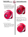
6 Sensor Assembly/Accessories
6.1 Flame Detectors .............................................................................. 25
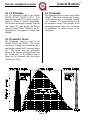
6.2 UV Phototube ................................................................................. 27
6.3 Pyroelectric Device ........................................................................ 27
6.4 Thermopile ..................................................................................... 27
6.5 Test Lamps ..................................................................................... 28
ii
Model TA402A
Table of Contents

Page
Number
7 Appendix
A Glossary of Terms .......................................................................... 30
B Engineering & Technical Drawings ............................................... 32
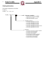
C Ordering Information ..................................................................... 40
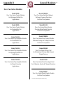
D Zero Two Series Modules .............................................................. 41
8 Index
...............................................................................................42
Illustrations
Figure 1 Isometric View of the Model TA402A....................................................1
Figure 2 Control Module Coding Strip ..................................................................7
Figure 3 Wire Strip Length.....................................................................................8
Figure 4 Rear Terminal Designations.....................................................................8
Figure 5 Relay Protection Circuit for AC Loads ...................................................9
Figure 6 Relay Protection Circuit for DC Loads...................................................10
Figure 7 Detector / Controller Connections ..........................................................10
Figure 8 Typical External Circuits for Open Collectors .......................................11
Figure 9 Card Test Switch Wiring.........................................................................11
Figure 10 Analog Signal Connections.....................................................................11
Figure 11 Power Connections - Rear Chassis.........................................................12
Figure 12 Front Panel Display.................................................................................17
Figure 13 Entering the Setup & Setup Check Modes .............................................19
Figure 14 Entering the Password ............................................................................19
Figure 15 Entering the Inhibit Mode ......................................................................20
Figure 16 A2 Energized/De-Energized Alarm Option ...........................................20
Figure 17 A2 Latching/Non-Latching Alarm Option .............................................20
Figure 18 A2 Alarm Time Delay Option ...............................................................21
Figure 19 A1 Energized/De-Energized Alarm Option ...........................................21
Figure 20 A1 Latching/Non-Latching Alarm Option .............................................21
Figure 21 Fault / Inhibit Option ..............................................................................22
Figure 22 Entering Card Test Options ....................................................................22
Figure 23 Alarm Output Option during a Card Test, Ac / nA ................................23
Figure 24 Password Enabled/Disabled Option .......................................................23
Figure 25 Entering a new Password .......................................................................23
Figure 26 FL3000 Picture .......................................................................................25
Figure 27 FL3001 Picture .......................................................................................25
Figure 28 FL3002 Picture .......................................................................................25
Figure 29 FL3100 Picture .......................................................................................26
Figure 30 FL3101 Picture .......................................................................................26
Figure 31 FL3102 Picture .......................................................................................26
Figure 32 Energy Spectrum ....................................................................................27
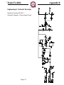
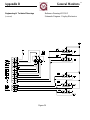
Figure 33 Schematic Diagram - Detector Input Circuit .........................................32
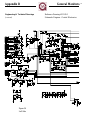
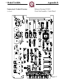
Figure 34 & 35 Schematic Diagram - Control Board .................................................33 & 34
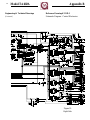
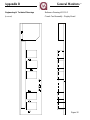
Figure 36 Schematic Diagram - Display Board .....................................................35
Figure 37 Circuit Card Assembly - Control Board ................................................36
Figure 38 Circuit Card Assembly - Display Board ................................................37
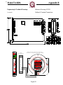
Figure 39 Outline & Terminal Connections ...........................................................38
Figure 40 Final Assembly Drawing .......................................................................39
iii
Table of Contents
General Monitors

This chapter provides a brief description of
the Model TA402A, its features & benefits
and a list of some of its applications. More
detailed information on the features and
benefits listed in section 1.2 will be
presented in later chapters.
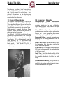
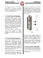
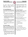
1.1 General Description
The General Monitors Model TA402A (see
figure 1) is a single channel Flame Detection
Trip Amplifier designed for use in Zero Two
Series Gas and Flame Detection Systems.
This Module connects to the wires from a
field mounted General Monitors Flame
Detector, which monitors the presence of
radiation emitted from fires.
The Model TA402A is electrically and
physically compatible with the other gas
detection and system modules in the Zero
Two Series. It is distinguished from the
other modules by its red border and
“TA402A" in the upper right corner of the
front panel. The Model TA402A is
designed for use in non-hazardous
environments.
Fig ure 1
1.2 Features & Benefits
Microprocessor Based Electronics:
monitors fault conditions, sensor inputs and
provides outputs in the form of display
codes, analog signal, relay contact and open
collector activations.
Setup Mode: allows the user to set
parameters such as alarm output options, test
options, etc. These parameters are viewed
on the display during the Setup Mode.
Password Option: prevents unauthorized
alteration of the setup parameters (can be
disabled).
Setup Check Mode: allows the user to view
the parameters that have been set by the
factory and/or an operator.
LED Test: tests the integrity of each display
LED and each segment of the digital display
on the front panel.
Card Test: tests the functionality of the
card through the microprocessor ramping up
the signal to the alarm level for the time
delay.
Live Insertion/Removal: allows the user to
insert or remove a module while power is
applied to the system without damage to any
of the components in the system.
Model TA402A
Introduction
1

1.3 Applications
The General Monitors Model TA402A is a
Trip Amplifier designed for Zero Two
Series Flame Detection Applications. Below
is a partial list of applications:
n Refineries
n Drilling platforms and rigs
n
Gas and oil production platforms
n Gas collection facilities
n LPG/LNG processing and storage
n
Gas turbines
n
Solvent vapors
n Chemical & petrochemical plants
n Paint spray booths
n
Aircraft hangars
Introduction
General Monitors
2

This chapter provides detailed specifications
for the Model TA402A Zero Two Series
Trip Amplifier Module. System,
mechanical, electrical and environmental
specifications present the Model TA402A
in technical terms. The engineering
specification provides a written specification
that can be inserted into another written
specification by architects and engineers.
2.1 System Specifications
Application:
Flame Detection.
Detector Type:
General Monitors’ FL3000 and FL3100
Flame Detectors.
Measuring Ranges (flame detectors):
UV Wavelength. 185 to 260nm
IR Wavelength... 4.3um (centerline)
Typical response times for TA402A
System:
with FL3000, FL3100 2 to 5 sec
with FL3001, FL3101 < 1 sec
with FL3002, FL3102 2 to 5 sec
Test Features:
Card - Functionality & Alarm Ramp
LED - Integrity of LED’s & Display
Front Panel Indicators:
DISPLAY - 2 x 7 Segments
A2 - Time Delayed Alarm
A1 - Immediate Warning
READY - Normal Operation
SETUP - Display / Change Parameters
Modes of Operation:
Setup, Setup Check, Inhibit & Normal
Approvals:
The Model TA402A is CSA certified.
Warranty:
Two Years
2.2 Mechanical Specifications
Weight: 11.2 oz. (318 grams)
Length: 9.9 inches (251 mm)
Height: 6.825 inches (173 mm)
Width: 1.0 inches (25 mm)
2.3 Electrical Specifications
Input Power Requirement:
20 to 35Vdc @ 375mA max. (24Vdc,
9W nominal with field device).
Electrical Classification:
General Monitor’s FL3000 and FL3100
Series Flame Detectors are rated for use
in Class I, Division 1, Groups B, C & D;
Class II, Groups E, F & G and Class III.
The Model TA402A is designed for use
in non-hazardous environments.
Relay Contact Rating:
4A @ 250Vac, 3A @ 30Vdc resistive
max. DPDT for A1 & A2, SPDT for
Fault.
Open Collector Rating:
100mA @ 35 Vdc for A1, A2, Fault,
UA, FUA, CAL-OC, LA1 & LA2.
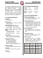
Cable Parameters:
Recommended three wire shielded,
maximum cable lengths allowable
between module and the Field Device
with 24Vdc nominal at the detector:
3
Model TA402A
Specifications
AWG Feet Me ters
14 4500 1372
16 2250 685
18 1600 488
20 1100 335
22 750 228

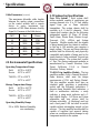
Cable Parameters (continued)
The maximum allowable cable lengths
between the analog output connections
on the control module with a remote
device in series (maximum loop
resistance of 300 Ohms between Analog
Signal & Common at the field device):
2.4 Environmental Specifications
Operating Temperature Range:
Field -40°F to +140°F
De vice -40°C to +60°C
TA402A 0°F to +150°F
-18°C to +66°C
Storage Temperature Range:
Field -40°F to +167°F
De vice -40°C to +70°C
TA402A -40°F to +150°F
-40°C to +66°C
Operating Humidity Range:
5% to 100% Rela tive Hu mid ity,
non- condensing
2.5 Engineering Specifications
Zero Two System - Each system shall
utilize modules capable of monitoring gas
sensing elements or a 0 to 21.7mA analog
signal from gas or flame detection
transmitters. The system chassis shall be
available in 4, 8 and 16 channels. Each
chassis shall contain a bus for the following
independent signals: A1 Warn, A2 Alarm,
Fault Alarm, Master Reset, Master Accept,
Unaccept, CAL, +24Vdc and System
Common. Module signals shall be capable
of being bussed from one chassis to another,
so that up to 100 modules can comprise a
single system. The gas and flame detection
modules shall be electrically and physically
compatible and capable of being used in the
same chassis to form combined fire and gas
detection systems. The system shall consist
of Zero Two Series component modules as
manufactured by General Monitors, Lake
Forest, California, U.S.A. or General
Monitors, Galway, Ireland.
TA402A Trip Amplifier Module - The trip
amplifier module, with a General Monitors’
flame detector, shall meet the design
requirements of CSA and Factory Mutual.
The trip amplifier module shall have an
interface panel, providing a mode/select
switch and the following indications: 2
discrete alarm threshold level indicators, a
fault or malfunction indicator, a ready
indicator, a setup mode indicator and a 2
digit digital display. All Warn and Alarm
parameters and user options shall be
software selectable. A functional card test
and a front panel LED test shall be switch
capable without interrupting normal on-line
services. The trip amplifier module shall be
capable of insertion and removal during
power on conditions without damage to any
component module in the system.
4
Specifications
General Monitors
AWG Feet Me ters
14 9000 2740
16 5200 1585
18 3800 1160
20 2400 730
22 1600 488

Engineering Specification (continued)
The trip amplifier module will generate
display codes associated with fault
conditions whenever a fault or malfunction
occurs. A mode/select switch shall provide
the operator front panel access to a setup
check mode, a setup mode and an inhibit
mode. The trip amplifier module shall have
a password protected setup routine capable
of having the password disabled.
5
Model TA402A
Specifications

6
General Monitors
This page left blank intentionally

This chapter discusses what to do when a
Model TA402A is received, the terminal
connections & designations, field device
location considerations and what to be
aware of when applying power.
3.1 Upon Receipt of Equipment
All equipment shipped by General Monitors
is packaged in shock absorbing containers
which provide considerable protection
against physical damage. The contents
should be carefully removed and checked
against the packing slip. If any damage has
occurred or if there is any discrepancy in the
order, notify General Monitors as soon as
possible. All subsequent correspondence
with General Monitors must specify the
equipment part and serial numbers.
Each Model TA402A is completely checked
at the factory, however, a complete
check-out is necessary upon initial
installation and start up to ensure system
integrity.
3.2 Control Module Installation
A rack or panel mounted chassis will be
required when installing any Zero Two
Series Module. These chassis should be
mounted in non-hazardous, weather
protected locations and should be subjected
to minimal shock and vibrations. The rack
and panel mounted chassis are available in
4, 8, and 16 channel sizes. Multiple 16
channel chassis may be connected to each
other to form larger systems.
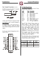
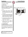
In installations where two or more module
types are to be mixed in the same chassis,
ensure that the individual coding strips
match the channel application. The coding
strips are pre-configured at the factory and
the male portion is already on each module.
The female portion, if unmounted, must be
fastened into position on the mounting strip
of the desired chassis channel so as to mate
with its counterpart on the module (see
figure 2 below).
Fig ure 2
Zero Two series modules require air
circulation to avoid excessive heat build-up.
If chassis are stacked vertically within an
enclosure, forced air circulation may be
required. The Trip Amplifier Modules are,
to a great extent, immune to electromagnetic
interference (EMI). However, they should
not be mounted in close proximity to radio
transmitters or similar equipment.
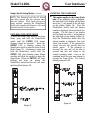
3.3 Rear Terminal Connections
All wire connections to the Model TA402A
are made to the terminal block located at the
rear of the chassis. The terminal block
accepts 16 AWG to 20 AWG, stranded or
solid core wire.
7
Model TA402A
Installation

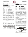
Rear Terminal Connections (continued)
14 AWG wire may be used if it is properly
stripped according to figure 3.
Fig ure 3
Contact with PC Board components should
be avoided in order to prevent damage by
static electricity.
To connect wires to the terminal block on
the Model TA402A, loosen the desired
screw, insert the stripped end of the wire and
tighten.
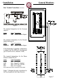
For the rear terminal designations refer to
figure 4 below:
Fig ure 4
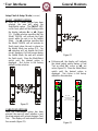
A2 Time De layed Alarm
The terminal designations for the A2 Time
Delayed Alarm outputs are:
La bel Term De scrip tion
A2- C1 2d Re lay Com mon (1&2)
A2-1 4d Re lay Con tact
A2-2 6d Re lay Con tact
A2-3 8d Re lay Con tact
A2-4 10d Re lay Con tact
A2- C2 12d Re lay Com mon (3 & 4)
A2- OC 14d Open Col lec tor (OC)
LA2 24z OC Logic for A2 LED
The A2 Time Delayed Alarm outputs are
DPDT relays, 1 open collector output
(A2-OC) that follows the logic of the relays
and 1 open collector output (LA2) that
follows the blinking pattern of the front
panel LED. The A2-C1 designation is
common for A2-1 & A2-2. The A2-C2
designation is common for A2-3 & A2-4.
The normally open (NO) and normally
closed (NC) contacts depend on a user
selectable option (see chapter 5).
The table below refers to the proper open
and closed A2 Time Delayed Alarm relay
contacts while the unit is on power:
8
Installation
General Monitors
User Se lected
Re lay State
Nor mally
Open
Nor mally
Closed
Nor mally
En er gized
A2- C1 & A2-1,
A2- C2 & A2-4
A2- C1 & A2-2,
A2- C2 & A2-3
Nor mally
De- Energized
A2- C1 & A2-2,
A2- C2 & A2-3
A2- C1 & A2-1,
A2- C2 & A2-4

Rear Ter mi nal Con nec tions (con tin ued)
A1 Im me di ate Warn
The terminal designations for the A1
Immediate Warn outputs are:
La bel Term De scrip tion
A1- C1 2z Re lay Com mon (1 &
2)
A1-1 4z Re lay Con tact
A1-2 6z Re lay Con tact
A1-3 8z Re lay Con tact
A1-4 10z Re lay Con tact
A1- C2 12z Re lay Com mon (3 & 4)
A1- OC 14z Open Col lec tor (OC)
LA1 24d OC Logic for A1 LED
The A1 Immediate Warn outputs are DPDT
relays, 1 open collector output (A1-OC) that
follows the logic of the relays and 1 open
collector output (LA1) that follows the
blinking pattern of the front panel LED.
The A1-C1 designation is common for A1-1
& A1-2. The A1-C2 designation is common
for A1-3 & A1-4. The normally open (NO)
and normally closed (NC) contacts depend
on a user selectable option (see chapter 5).
The table below refers to the proper open
and closed A1 Immediate Warn relay
contacts while the unit is on power:
Fault Alarm
The terminal designations for the Fault
outputs are:
La bel Term De scrip tion
F-C 16z Re lay Com mon
F-1 18z Re lay Con tact (NO)
F-2 20z Re lay Con tact (NC)
F-OC 22z Open Col lec tor (OC)
FUA 32d Open Col lec tor (OC)
The Fault outputs are SPDT relays, 1 open
collector output (F-OC) that follows the
logic of the relays and 1 open collector
output (FUA) dedicated to new fault
indications. If the Backwards Compatible
configuration is ordered, the FUA will not
be present (pin 32d will be for +B, alternate
power supply). The Fault outputs are always
normally energized when power is applied
to the module.
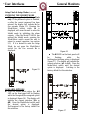
The contact ratings for the A2 & A1 alarm
and Fault relays are 4A @ 250 Vac, 3A @
30 Vdc, Resistive, maximum.
Inductive loads (bells, buzzers, relays, etc.)
on dry relay contacts must be clamped
down. Unclamped inductive loads can
generate voltage spikes in excess of 1000
volts. Spikes of this magnitude may cause
false alarms and contact damage. Figures 5
& 6 show recommended relay protection
circuits for AC and DC loads, respectively.
Fig ure 5
9
Installation
Model TA402A
User Se lected
Re lay State
Nor mally
Open
Nor mally
Closed
Nor mally
En er gized
A1- C1 & A1-1,
A1- C2 & A1-4
A1- C1 & A1-2,
A1- C2 & A1-3
Nor mally
De- Energized
A1- C1 & A1-2,
A1- C2 & A1-3
A1- C1 & A1-1,
A1- C2 & A1-4

Rear Terminal Connections (continued)
Fig ure 6
The terminal designation for the Unaccept
output is:
Label Term De scrip tion
UA 18d Open Col lec tor Out put
The terminal designations for the Discrete
Inhibit indication is:
La bel Term De scrip tion
CAL/INH 32z Open Col lec tor Out put
If the Backwards Compatible configuration
is ordered, the CAL/INH will not be present
(pin 32z will be for 0v, alternate COM).
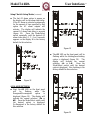
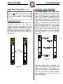
The terminal designations for the Flame
Detector connections are:
La bel Term De scrip tion
WHT 26d,z Sig nal IN (Ana log)
RED 28d,z VDC Out (+24Vdc)
BLK 30d,z DC Com mon
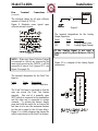
Only one Flame De tec tor may be con nected to a Model TA402A.
Figure 7 illustrates the inter-connections for
the Trip Amplifier & the Flame Detector.
10
Installation
General Monitors
Fig ure 7

Rear Terminal Connections
(continued)
The electrical rating for all open collector
outputs is 100mA @ 35 Vdc.
Figure 8 illustrates some typical open
collector external circuits.
Fig ure 8
NOTE: When any Open Collector Output
is connected to a device not powered by the
same supply powering the TA402A, it will be
necessary to remove (cut) Jumper W11 (see
figure 33 on page 35).
The terminal designation for the Card Test
Input is:
La bel Term De scrip tion
CT 16d Switch Con nec tion
The Card Test Input is provided so that the
user can access the Card Test feature
remotely. One end of a normally open
SPST switch is connected to this termination
and the other end is connected to system
common. To activate the feature, simply
press and hold the switch for as long as the
test time is to be run (the minimum runtime
for this test is equal to the A2 time delay).
Figure 9 is a block diagram that shows the
switch connections for the Card Test feature.
Fig ure 9
The terminal designations for the Analog
Output Signal are:
La bel Term De scrip tion
AO+ 20d Ana log Sig nal (plus)
AO- 22d Ana log Sig nal (mi nus)
If the Analog Signal is not used a
jumper must be placed between 20d &
22d.
Figure 10 is a diagram of the Analog Signal
connections.
Fig ure 10
11
Installation
Model TA402A

3.4 Detector Location
Considerations
There are no standard rules for detector
placement since the optimum location is
different for each application. The customer
must evaluate conditions at the detector site
in order to make this determination.
Gen erally:
n
The flame detector should be easily
accessible for optical checks. Ensure
that sufficient clearance exists to allow
the use of field devices such as the Air
Purge Guard.
n The flame detector head should always
be pointing at a slight downward angle to
prevent build up of dust and particulate
matter on the window(s). Remember
that flame detectors are optical devices.
n
The flame detector should be located in
areas where fires may be likely to occur,
if their presence is dangerous.
n
Multiple flame detectors should be
positioned such that their vertical and
horizontal fields of view overlap, to
ensure adequate coverage.
3.5 Applying Power
Zero Two Series Modules do not have an
ON/OFF power switch. Each module in the
Zero Two Series operates from 24 Vdc.
Power requirements will vary according to
the number and type of modules in the
system, as well as the number and type of
field devices.
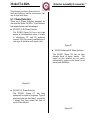
Figure 11 indicates where the power
connections for the chassis are made.
12
Installation
General Monitors
NOTE: if the application of power does
not turn ON the unit, check fuse F1 on
the control board.
Fig ure 11

This chapter discusses what general
maintenance to perform, describes the
electrical inputs, outputs, accepting &
resetting alarm, calibration & fault
conditions and fault diagnostics.
4.1 General Maintenance
Once the Model TA402A has been installed,
very little maintenance is required other than
periodic checks to verify the integrity of the
system.
n
The user should evaluate conditions at
the detector site to determine how
frequent checks should be performed.
n A functional test of the system should be
performed at least once each year. This
test should include full operation of
stand-by systems or back up power for
the prescribed period.
n
The power, detector and output wiring
should be checked for tightness,
verifying that all of the components and
devices are connected correctly.
n
If the “Password” is disabled, periodic
checks of the setup parameters should be
performed.
4.2 Electrical Inputs
There are two electrical inputs to the Model
TA402A. They are the General Monitors’
Field Device and the Card Test input. Both
of these input connections (field device and
card test) are made to the rear terminal block
(see chapter 3 for more detailed installation
information).
n
The Flame Detector input consists of the
standard three lead connections used
with General Monitors’ Field Devices
(Black = Common, White = Signal, Red
= +24Vdc). See figure 8 on page 10 of
this manual.
n The Card Test input consists of a single
termination for remote testing of the
Model TA402A’s functions. For
detailed information on the Card Test,
refer to figure 9 on page 11 of this
manual.
4.3 Electrical Outputs
The electrical outputs on the Model
TA402A consist of relay contacts, open
collectors and an analog current signal.
n
The following outputs have rear terminal
relay contacts:
A1 Alarm - DPDT relay contacts
A2 Alarm - DPDT relay contacts
Fault - SPDT relay contacts
All of the relay contacts on the Model
TA402A have a maximum rating of:
4A @ 250Vac, 3A @ 30Vdc resistive
n
The following outputs have rear terminal
open collectors:
A1 Alarm & LED Mimic
A2 Alarm & LED Mimic
Fault
UA - Unaccepted Alarm
FUA - Unaccepted Fault
CAL/INH - Discrete Inhibit Indication
All of the open collector outputs on the
Model TA402A have a maximum rating of:
100mA @ 35Vdc
13
Model TA402A
Operation

Elec tri cal Out puts (con tin ued)
n
The Model TA402A provides an Analog
Output Signal for interfacing with other
external devices (
i.e. PLC, Chart Recorder, etc.
).
This signal originates at the Flame Detector
and passes through “Signal IN” of the Trip
Amplifier, out “AO+” to the external device
and must be returned to “AO-” of the Trip
Amplifier. The signal from the Flame
Detector is a stepped 0 to 20mA signal:
0mA Fault Condition
2mA COPM Fault (FL310X only)
4mA Safe Condition
8mA IR Presence (FL3000, FL3100 only)
12mA UV Presence (FL3000, FL3100
only)
16mA Immediate indication of the
presence of flame radiation
20mA Sufficient Flame Radiation present
for the duration of a user specified
time delay in the Flame Detector
The Model TA402A interprets the analog
signal from the Flame Detector as follows:
0mA Fault Condition, The TA402A will
display a Fault Code & activate
the Fault LED and circuit.
2mA COPM Fault, The TA402A will
display a Fault Code & activate
the Fault LED and circuit.
4mA Safe Condition, The TA402A will
activate the Ready LED.
16mA Flame Radiation, The TA402A
will activate the A1 Alarm LED
and circuit and begin the Time
Delay count. If a 16mA (or
higher) signal is maintained
continuously for the period of
the Time Delay the TA402A will
activate the A2 Alarm LED and
circuit.
The maximum resistance load on the Analog
Signal loop, including the wire running from
the Flame Detector to the Trip Amplifier and
to any External Device, must not exceed 300
ohms.
If the Analog Output is not used to interface with
an external device, a jumper must be placed
between “AO+” & “AO-” on the rear terminal of
the Trip Amplifier (see section 3.3, page 10).
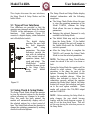
4.4 Accepting Alarm Conditions
Whenever a new alarm condition occurs the front
panel LED and open collector associated with that
alarm (LA1 or LA2) will flash. In addition, the
associated alarm outputs and the unaccept outputs
(TA402A, UA open collector & FM002A, UA
relay) will activate, unless they are already
activated. The flashing front panel alarm LED
and rear terminal open collector indicate that a
new alarm has been activated. New alarms
should be acknowledged or accepted. This is
accomplished with the Master Accept Button
located on the Facilities Module. Pressing the
Master Accept Button de-activates the UA
outputs and causes the associated front panel
alarm LED and rear terminal open collector to
stop flashing and energize.
NOTE: Latching alarms must be Accepted
before they can be Reset (see section 4.5).
There is a unique situation that may occur with
some frequency in certain applications. An alarm
may occur and the operator will accept this alarm
by pressing the Master Accept Button. If the
alarm output is latching and the condition at the
detector returns to normal (safe) the alarm output
will need to be reset. If, however, the alarm
output is accepted but not reset and that alarm
condition occurs again, the front panel LED, the
associated mimic open collector and the unaccept
outputs will reflash or re-activate. This gives the
operator an indication of a new alarm condition
that must be re-accepted.
14
Operation
General Monitors

ModelTA402A
Operation

Operation
GeneralMonitors
La pagina si sta caricando...
La pagina si sta caricando...
La pagina si sta caricando...
La pagina si sta caricando...
La pagina si sta caricando...
La pagina si sta caricando...
La pagina si sta caricando...
La pagina si sta caricando...
La pagina si sta caricando...
La pagina si sta caricando...
La pagina si sta caricando...
La pagina si sta caricando...
La pagina si sta caricando...
La pagina si sta caricando...
La pagina si sta caricando...
La pagina si sta caricando...
La pagina si sta caricando...
La pagina si sta caricando...
La pagina si sta caricando...
La pagina si sta caricando...
La pagina si sta caricando...
La pagina si sta caricando...
La pagina si sta caricando...
La pagina si sta caricando...
La pagina si sta caricando...
La pagina si sta caricando...
La pagina si sta caricando...
La pagina si sta caricando...
La pagina si sta caricando...
La pagina si sta caricando...
La pagina si sta caricando...
-
 1
1
-
 2
2
-
 3
3
-
 4
4
-
 5
5
-
 6
6
-
 7
7
-
 8
8
-
 9
9
-
 10
10
-
 11
11
-
 12
12
-
 13
13
-
 14
14
-
 15
15
-
 16
16
-
 17
17
-
 18
18
-
 19
19
-
 20
20
-
 21
21
-
 22
22
-
 23
23
-
 24
24
-
 25
25
-
 26
26
-
 27
27
-
 28
28
-
 29
29
-
 30
30
-
 31
31
-
 32
32
-
 33
33
-
 34
34
-
 35
35
-
 36
36
-
 37
37
-
 38
38
-
 39
39
-
 40
40
-
 41
41
-
 42
42
-
 43
43
-
 44
44
-
 45
45
-
 46
46
-
 47
47
-
 48
48
-
 49
49
-
 50
50
-
 51
51


General Monitors TA402A Single Channel Trip Amplifier Manuale del proprietario
- Tipo
- Manuale del proprietario
- Questo manuale è adatto anche per
in altre lingue
Altri documenti
-
ABB RED650 Applications Manual
-
Crowcon Hydra256 Istruzioni per l'uso
-
ADEMCO Security System VISTA-15CN Guida d'installazione
-
ABB REL650 series Applications Manual
-
-
-
Pyronix Matrix 832 Guida d'installazione
-
Omega CN3240 Series Manuale del proprietario
-
Eurotherm 306 6 channel multi point recorder Manuale del proprietario
-
Regal 42 Fly-Grande Coupe Manuale del proprietario