
—
RELION® 650 SERIES
Line differential protection RED650
Version 2.1
Application manual


Document ID: 1MRK 505 363-UEN
Issued: March 2019
Revision: A
Product version: 2.1
© Copyright 2016 ABB. All rights reserved

Copyright
This document and parts thereof must not be reproduced or copied without written
permission from ABB, and the contents thereof must not be imparted to a third party, nor
used for any unauthorized purpose.
The software and hardware described in this document is furnished under a license and may
be used or disclosed only in accordance with the terms of such license.
This product includes software developed by the OpenSSL Project for use in the OpenSSL
Toolkit. (http://www.openssl.org/) This product includes cryptographic software written/
developed by: Eric Young ([email protected]) and Tim Hudson ([email protected]).
Trademarks
ABB and Relion are registered trademarks of the ABB Group. All other brand or product names
mentioned in this document may be trademarks or registered trademarks of their respective
holders.
Warranty
Please inquire about the terms of warranty from your nearest ABB representative.

Disclaimer
The data, examples and diagrams in this manual are included solely for the concept or product
description and are not to be deemed as a statement of guaranteed properties. All persons
responsible for applying the equipment addressed in this manual must satisfy themselves that
each intended application is suitable and acceptable, including that any applicable safety or
other operational requirements are complied with. In particular, any risks in applications where
a system failure and/or product failure would create a risk for harm to property or persons
(including but not limited to personal injuries or death) shall be the sole responsibility of the
person or entity applying the equipment, and those so responsible are hereby requested to
ensure that all measures are taken to exclude or mitigate such risks.
This document has been carefully checked by ABB but deviations cannot be completely ruled
out. In case any errors are detected, the reader is kindly requested to notify the manufacturer.
Other than under explicit contractual commitments, in no event shall ABB be responsible or
liable for any loss or damage resulting from the use of this manual or the application of the
equipment.

Conformity
This product complies with the directive of the Council of the European Communities on the
approximation of the laws of the Member States relating to electromagnetic compatibility
(EMC Directive 2004/108/EC) and concerning electrical equipment for use within specified
voltage limits (Low-voltage directive 2006/95/EC). This conformity is the result of tests
conducted by ABB in accordance with the product standard EN 60255-26 for the EMC directive,
and with the product standards EN 60255-1 and EN 60255-27 for the low voltage directive. The
product is designed in accordance with the international standards of the IEC 60255 series.

Table of contents
Section 1 Introduction.......................................................................................................15
1.1 This manual....................................................................................................................................... 15
1.2 Intended audience............................................................................................................................15
1.3 Product documentation..................................................................................................................16
1.3.1 Product documentation set...................................................................................................... 16
1.3.2 Document revision history......................................................................................................... 17
1.3.3 Related documents......................................................................................................................17
1.4 Document symbols and conventions...........................................................................................18
1.4.1 Symbols......................................................................................................................................... 18
1.4.2 Document conventions...............................................................................................................19
1.5 IEC 61850 edition 1 / edition 2 mapping..................................................................................... 19
Section 2 Application.........................................................................................................23
2.1 General IED application...................................................................................................................23
2.2 Main protection functions............................................................................................................. 24
2.3 Back-up protection functions....................................................................................................... 24
2.4 Control and monitoring functions................................................................................................25
2.5 Communication................................................................................................................................ 27
2.6 Basic IED functions..........................................................................................................................29
Section 3 Configuration.................................................................................................... 31
3.1 Description of configuration RED650.......................................................................................... 31
3.1.1 Introduction.................................................................................................................................. 31
3.1.1.1 Description of A11.....................................................................................................................31
Section 4 Analog inputs.................................................................................................... 33
4.1 Introduction...................................................................................................................................... 33
4.2 Setting guidelines............................................................................................................................ 33
4.2.1 Setting of the phase reference channel.................................................................................. 33
4.2.1.1 Example...................................................................................................................................... 33
4.2.2 Setting of current channels.......................................................................................................34
4.2.2.1 Example 1................................................................................................................................... 34
4.2.2.2 Example 2...................................................................................................................................35
4.2.2.3 Example 3...................................................................................................................................36
4.2.2.4 Examples on how to connect, configure and set CT inputs for most commonly
used CT connections............................................................................................................... 38
4.2.2.5 Example on how to connect a star connected three-phase CT set to the IED............ 39
4.2.2.6 Example how to connect delta connected three-phase CT set to the IED...................43
4.2.2.7 Example how to connect single-phase CT to the IED.......................................................45
4.2.3 Relationships between setting parameter Base Current, CT rated primary
current and minimum pickup of a protection IED................................................................ 46
4.2.4 Setting of voltage channels.......................................................................................................47
Table of contents
1
Application manual

4.2.4.1 Example......................................................................................................................................47
4.2.4.2 Examples how to connect, configure and set VT inputs for most commonly
used VT connections............................................................................................................... 47
4.2.4.3 Examples on how to connect a three phase-to-earth connected VT to the IED......... 48
4.2.4.4 Example on how to connect a phase-to-phase connected VT to the IED.................... 50
4.2.4.5 Example on how to connect an open delta VT to the IED for high impedance
earthed or unearthed netwoeks............................................................................................52
4.2.4.6 Example how to connect the open delta VT to the IED for low impedance
earthed or solidly earthed power systems......................................................................... 53
4.2.4.7 Example on how to connect a neutral point VT to the IED.............................................. 55
Section 5 Local HMI........................................................................................................... 59
5.1 Display............................................................................................................................................... 60
5.2 LEDs.................................................................................................................................................... 61
5.3 Keypad................................................................................................................................................62
5.4 Local HMI functionality...................................................................................................................64
5.4.1 Protection and alarm indication...............................................................................................64
5.4.2 Parameter management ........................................................................................................... 65
5.4.3 Front communication.................................................................................................................65
Section 6 Differential protection.....................................................................................67
6.1 Low impedance restricted earth fault protection REFPDIF ................................................... 67
6.1.1 Identification................................................................................................................................ 67
6.1.2 Application.................................................................................................................................... 67
6.1.2.1 Transformer winding, solidly earthed................................................................................. 68
6.1.2.2 Transformer winding, earthed through zig-zag earthing transformer........................ 68
6.1.2.3 Autotransformer winding, solidly earthed......................................................................... 69
6.1.2.4 Reactor winding, solidly earthed.......................................................................................... 70
6.1.2.5 CT earthing direction...............................................................................................................71
6.1.3 Setting guidelines........................................................................................................................ 71
6.1.3.1 Setting and configuration.......................................................................................................71
6.1.3.2 Settings...................................................................................................................................... 72
6.2 Line differential protection............................................................................................................73
6.2.1 Identification................................................................................................................................ 73
6.2.2 Application.................................................................................................................................... 73
6.2.2.1 Power transformers in the protected zone........................................................................ 74
6.2.2.2 Small power transformers in a tap....................................................................................... 75
6.2.2.3 Charging current compensation........................................................................................... 75
6.2.2.4 Time synchronization.............................................................................................................. 77
6.2.2.5 Analog signal communication for line differential protection........................................77
6.2.2.6 Configuration of analog signals............................................................................................78
6.2.2.7 Configuration of LDCM output signals................................................................................79
6.2.2.8 Open CT detection...................................................................................................................80
6.2.3 Setting guidelines........................................................................................................................81
6.2.3.1 General settings........................................................................................................................81
6.2.3.2 Percentage restrained differential operation.................................................................... 82
6.2.3.3 The 2nd and 5th harmonic analysis...................................................................................... 85
Table of contents
2
Application manual

6.2.3.4 Internal/external fault discriminator...................................................................................86
6.2.3.5 Power transformer in the protected zone.......................................................................... 87
6.2.3.6 Settings examples................................................................................................................... 90
Section 7 Impedance protection....................................................................................101
7.1 Distance protection ZMFPDIS..................................................................................................... 101
7.1.1 Identification.............................................................................................................................. 101
7.1.2 Application.................................................................................................................................. 101
7.1.2.1 System earthing......................................................................................................................101
7.1.2.2 Fault infeed from remote end............................................................................................. 104
7.1.2.3 Load encroachment...............................................................................................................105
7.1.2.4 Short line application............................................................................................................ 106
7.1.2.5 Long transmission line application.................................................................................... 106
7.1.2.6 Parallel line application with mutual coupling..................................................................107
7.1.2.7 Tapped line application......................................................................................................... 112
7.1.3 Setting guidelines...................................................................................................................... 114
7.1.3.1 General......................................................................................................................................114
7.1.3.2 Setting of zone 1..................................................................................................................... 115
7.1.3.3 Setting of overreaching zone............................................................................................... 115
7.1.3.4 Setting of reverse zone..........................................................................................................116
7.1.3.5 Setting of zones for parallel line application.................................................................... 116
7.1.3.6 Setting the reach with respect to load...............................................................................118
7.1.3.7 Zone reach setting lower than minimum load impedance............................................ 118
7.1.3.8 Zone reach setting higher than minimum load impedance.......................................... 120
7.1.3.9 Other settings......................................................................................................................... 121
7.2 Automatic switch onto fault logic ZCVPSOF ...........................................................................124
7.2.1 Identification.............................................................................................................................. 124
7.2.2 Application.................................................................................................................................. 124
7.2.3 Setting guidelines......................................................................................................................125
Section 8 Current protection..........................................................................................127
8.1 Instantaneous phase overcurrent protection PHPIOC .......................................................... 127
8.1.1 Identification.............................................................................................................................. 127
8.1.2 Application.................................................................................................................................. 127
8.1.3 Setting guidelines...................................................................................................................... 127
8.1.3.1 Meshed network without parallel line................................................................................ 128
8.1.3.2 Meshed network with parallel line...................................................................................... 130
8.2 Four step phase overcurrent protection OC4PTOC................................................................ 131
8.2.1 Identification...............................................................................................................................131
8.2.2 Application...................................................................................................................................131
8.2.3 Setting guidelines......................................................................................................................132
8.2.3.1 Settings for each step........................................................................................................... 133
8.2.3.2 2nd harmonic restrain........................................................................................................... 136
8.3 Instantaneous residual overcurrent protection EFPIOC .......................................................140
8.3.1 Identification.............................................................................................................................. 141
8.3.2 Application.................................................................................................................................. 141
8.3.3 Setting guidelines...................................................................................................................... 141
Table of contents
3
Application manual

8.4 Four step residual overcurrent protection EF4PTOC ............................................................ 143
8.4.1 Identification.............................................................................................................................. 143
8.4.2 Application.................................................................................................................................. 143
8.4.3 Setting guidelines..................................................................................................................... 145
8.4.3.1 Settings for each step (x = 1, 2, 3 and 4)............................................................................ 145
8.4.3.2 Common settings for all steps............................................................................................ 147
8.4.3.3 2nd harmonic restrain........................................................................................................... 148
8.4.3.4 Parallel transformer inrush current logic.......................................................................... 148
8.4.3.5 Switch onto fault logic.......................................................................................................... 149
8.4.3.6 Line application example......................................................................................................150
8.5 Sensitive directional residual overcurrent and power protection SDEPSDE ....................154
8.5.1 Identification.............................................................................................................................. 154
8.5.2 Application..................................................................................................................................154
8.5.3 Setting guidelines......................................................................................................................156
8.6 Breaker failure protection CCRBRF............................................................................................ 162
8.6.1 Identification.............................................................................................................................. 163
8.6.2 Application.................................................................................................................................. 163
8.6.3 Setting guidelines......................................................................................................................163
8.7 Stub protection STBPTOC ...........................................................................................................166
8.7.1 Identification.............................................................................................................................. 166
8.7.2 Application..................................................................................................................................166
8.7.3 Setting guidelines......................................................................................................................167
8.8 Pole discordance protection CCPDSC....................................................................................... 167
8.8.1 Identification.............................................................................................................................. 168
8.8.2 Application..................................................................................................................................168
8.8.3 Setting guidelines..................................................................................................................... 168
8.9 Directional underpower protection GUPPDUP........................................................................ 169
8.9.1 Identification.............................................................................................................................. 169
8.9.2 Application..................................................................................................................................169
8.9.3 Setting guidelines...................................................................................................................... 171
8.10 Directional overpower protection GOPPDOP ..........................................................................174
8.10.1 Identification.............................................................................................................................. 174
8.10.2 Application.................................................................................................................................. 174
8.10.3 Setting guidelines......................................................................................................................176
8.11 Broken conductor check BRCPTOC ........................................................................................... 179
8.11.1 Identification.............................................................................................................................. 179
8.11.2 Application.................................................................................................................................. 179
8.11.3 Setting guidelines......................................................................................................................179
Section 9 Voltage protection......................................................................................... 181
9.1 Two step undervoltage protection UV2PTUV ..........................................................................181
9.1.1 Identification.............................................................................................................................. 181
9.1.2 Application.................................................................................................................................. 181
9.1.3 Setting guidelines...................................................................................................................... 181
9.1.3.1 Equipment protection, such as for motors and generators......................................... 182
9.1.3.2 Disconnected equipment detection...................................................................................182
Table of contents
4
Application manual

9.1.3.3 Power supply quality .............................................................................................................182
9.1.3.4 Voltage instability mitigation.............................................................................................. 182
9.1.3.5 Backup protection for power system faults..................................................................... 182
9.1.3.6 Settings for Two step undervoltage protection.............................................................. 182
Section 10 Multipurpose protection............................................................................... 185
10.1 General current and voltage protection CVGAPC....................................................................185
10.1.1 Identification.............................................................................................................................. 185
10.1.2 Application..................................................................................................................................185
10.1.2.1 Current and voltage selection for CVGAPC function...................................................... 186
10.1.2.2 Base quantities for CVGAPC function................................................................................ 188
10.1.2.3 Application possibilities....................................................................................................... 188
10.1.2.4 Inadvertent generator energization...................................................................................189
10.1.3 Setting guidelines..................................................................................................................... 190
10.1.3.1 Directional negative sequence overcurrent protection................................................. 190
10.1.3.2 Negative sequence overcurrent protection...................................................................... 191
10.1.3.3 Generator stator overload protection in accordance with IEC or ANSI standards...193
10.1.3.4 Open phase protection for transformer, lines or generators and circuit
breaker head flashover protection for generators..........................................................195
10.1.3.5 Voltage restrained overcurrent protection for generator and step-up
transformer............................................................................................................................. 196
10.1.3.6 Loss of excitation protection for a generator..................................................................196
Section 11 Secondary system supervision..................................................................... 199
11.1 Current circuit supervision CCSSPVC........................................................................................ 199
11.1.1 Identification.............................................................................................................................. 199
11.1.2 Application..................................................................................................................................199
11.1.3 Setting guidelines..................................................................................................................... 199
11.2 Fuse failure supervision FUFSPVC............................................................................................. 200
11.2.1 Identification............................................................................................................................. 200
11.2.2 Application................................................................................................................................. 200
11.2.3 Setting guidelines......................................................................................................................201
11.2.3.1 General......................................................................................................................................201
11.2.3.2 Setting of common parameters..........................................................................................201
11.2.3.3 Negative sequence based.....................................................................................................201
11.2.3.4 Zero sequence based............................................................................................................ 202
11.2.3.5 Delta U and delta I .................................................................................................................203
11.2.3.6 Dead line detection................................................................................................................203
Section 12 Control............................................................................................................. 205
12.1 Synchrocheck, energizing check, and synchronizing SESRSYN............................................205
12.1.1 Identification..............................................................................................................................205
12.1.2 Application..................................................................................................................................205
12.1.2.1 Synchronizing......................................................................................................................... 205
12.1.2.2 Synchrocheck..........................................................................................................................206
12.1.2.3 Energizing check.................................................................................................................... 208
12.1.2.4 Voltage selection................................................................................................................... 208
Table of contents
5
Application manual

12.1.2.5 External fuse failure.............................................................................................................. 209
12.1.3 Application examples................................................................................................................210
12.1.3.1 Single circuit breaker with single busbar.......................................................................... 210
12.1.3.2 Single circuit breaker with double busbar, external voltage selection........................211
12.1.3.3 Single circuit breaker with double busbar, internal voltage selection.........................211
12.1.4 Setting guidelines...................................................................................................................... 212
12.2 Autorecloser for 1 phase, 2 phase and/or 3 phase operation SMBRREC ........................... 216
12.2.1 Identification.............................................................................................................................. 216
12.2.2 Application.................................................................................................................................. 216
12.2.2.1 Auto-reclosing operation OFF and ON...............................................................................219
12.2.2.2 Start auto-reclosing and conditions for start of a reclosing cycle.............................. 219
12.2.2.3 Start auto-reclosing from CB open information............................................................. 220
12.2.2.4 Blocking of the autorecloser................................................................................................220
12.2.2.5 Control of the auto-reclosing open time for shot 1........................................................ 220
12.2.2.6 Long trip signal....................................................................................................................... 221
12.2.2.7 Maximum number of reclosing shots.................................................................................221
12.2.2.8
ARMode
=
3ph,
(normal setting for a single 3 phase shot).............................................. 221
12.2.2.9
ARMode
=
1/2/3ph
................................................................................................................... 221
12.2.2.10
ARMode
=
1/2ph
, 1-phase or 2-phase reclosing in the first shot....................................222
12.2.2.11
ARMode
=1ph + 1*2ph, 1-phase or 2-phase reclosing in the first shot......................... 222
12.2.2.12 ARMode=1/2ph + 1*3ph, 1-phase, 2-phase or 3-phase reclosing in the first shot.....222
12.2.2.13
ARMode
=1ph + 1*2/3ph, 1-phase, 2-phase or 3-phase reclosing in the first shot.....222
12.2.2.14 External selection of auto-reclose mode...........................................................................223
12.2.2.15 Reclosing reclaim timer.........................................................................................................223
12.2.2.16 Pulsing of the CB closing command and Counter........................................................... 223
12.2.2.17 Transient fault........................................................................................................................ 224
12.2.2.18 Permanent fault and reclosing unsuccessful signal....................................................... 224
12.2.2.19 Lock-out initiation................................................................................................................. 224
12.2.2.20 Evolving fault...........................................................................................................................225
12.2.2.21 Automatic continuation of the reclosing sequence .......................................................226
12.2.2.22 Thermal overload protection holding the auto-reclosing function back ...................226
12.2.3 Setting guidelines..................................................................................................................... 226
12.2.3.1 Configuration..........................................................................................................................226
12.2.3.2 Auto-recloser parameter settings...................................................................................... 229
12.3 Apparatus control APC..................................................................................................................232
12.3.1 Application.................................................................................................................................. 232
12.3.1.1 Bay control (QCBAY).............................................................................................................. 235
12.3.1.2 Switch controller (SCSWI).....................................................................................................236
12.3.1.3 Switches (SXCBR/SXSWI)..................................................................................................... 237
12.3.1.4 Reservation function (QCRSV and RESIN)......................................................................... 237
12.3.2 Interaction between modules.................................................................................................239
12.3.3 Setting guidelines..................................................................................................................... 240
12.3.3.1 Bay control (QCBAY)..............................................................................................................240
12.3.3.2 Switch controller (SCSWI)..................................................................................................... 241
12.3.3.3 Switch (SXCBR/SXSWI)......................................................................................................... 242
12.3.3.4 Bay Reserve (QCRSV).............................................................................................................242
Table of contents
6
Application manual

12.3.3.5 Reservation input (RESIN).................................................................................................... 242
12.4 Logic rotating switch for function selection and LHMI presentation SLGAPC.................242
12.4.1 Identification..............................................................................................................................242
12.4.2 Application..................................................................................................................................242
12.4.3 Setting guidelines..................................................................................................................... 243
12.5 Selector mini switch VSGAPC...................................................................................................... 243
12.5.1 Identification..............................................................................................................................243
12.5.2 Application..................................................................................................................................243
12.5.3 Setting guidelines..................................................................................................................... 244
12.6 Generic communication function for Double Point indication DPGAPC............................ 244
12.6.1 Identification..............................................................................................................................244
12.6.2 Application................................................................................................................................. 244
12.6.3 Setting guidelines..................................................................................................................... 245
12.7 Single point generic control 8 signals SPC8GAPC.................................................................. 245
12.7.1 Identification..............................................................................................................................245
12.7.2 Application..................................................................................................................................245
12.7.3 Setting guidelines..................................................................................................................... 246
12.8 AutomationBits, command function for DNP3.0 AUTOBITS................................................ 246
12.8.1 Identification..............................................................................................................................246
12.8.2 Application..................................................................................................................................246
12.8.3 Setting guidelines..................................................................................................................... 246
12.9 Single command, 16 signals SINGLECMD................................................................................. 246
12.9.1 Identification..............................................................................................................................247
12.9.2 Application..................................................................................................................................247
12.9.3 Setting guidelines..................................................................................................................... 248
Section 13 Scheme communication.................................................................................251
13.1 Scheme communication logic for distance or overcurrent protection ZCPSCH...............251
13.1.1 Identification.............................................................................................................................. 251
13.1.2 Application.................................................................................................................................. 251
13.1.2.1 Blocking schemes...................................................................................................................251
13.1.2.2 Delta blocking scheme.......................................................................................................... 252
13.1.2.3 Permissive schemes.............................................................................................................. 253
13.1.2.4 Intertrip scheme.....................................................................................................................255
13.1.3 Setting guidelines..................................................................................................................... 256
13.1.3.1 Blocking scheme.................................................................................................................... 256
13.1.3.2 Delta blocking scheme..........................................................................................................256
13.1.3.3 Permissive underreaching scheme..................................................................................... 257
13.1.3.4 Permissive overreaching scheme........................................................................................257
13.1.3.5 Unblocking scheme................................................................................................................257
13.1.3.6 Intertrip scheme..................................................................................................................... 257
13.2 Current reversal and Weak-end infeed logic for distance protection 3-phase
ZCRWPSCH ..................................................................................................................................... 257
13.2.1 Identification.............................................................................................................................. 257
13.2.2 Application..................................................................................................................................258
13.2.2.1 Current reversal logic............................................................................................................ 258
13.2.2.2 Weak-end infeed logic...........................................................................................................258
Table of contents
7
Application manual

13.2.3 Setting guidelines..................................................................................................................... 259
13.2.3.1 Current reversal logic............................................................................................................ 259
13.2.3.2 Weak-end infeed logic...........................................................................................................259
13.3 Current reversal and weak-end infeed logic for phase segregated communication
ZC1WPSCH ..................................................................................................................................... 260
13.3.1 Identification..............................................................................................................................260
13.3.2 Application................................................................................................................................. 260
13.3.3 Setting guidelines......................................................................................................................261
13.4 Local acceleration logic ZCLCPSCH........................................................................................... 262
13.4.1 Identification..............................................................................................................................262
13.4.2 Application..................................................................................................................................262
13.4.3 Setting guidelines..................................................................................................................... 263
Section 14 Logic.................................................................................................................265
14.1 Tripping logic SMPPTRC .............................................................................................................. 265
14.1.1 Identification..............................................................................................................................265
14.1.2 Application..................................................................................................................................265
14.1.2.1 Three-phase tripping ........................................................................................................... 266
14.1.2.2 Single- and/or three-phase tripping..................................................................................266
14.1.2.3 Single-, two- or three-phase tripping.................................................................................267
14.1.2.4 Lock-out...................................................................................................................................268
14.1.2.5 Blocking of the function block............................................................................................ 268
14.1.3 Setting guidelines..................................................................................................................... 268
14.2 Trip matrix logic TMAGAPC......................................................................................................... 268
14.2.1 Identification..............................................................................................................................269
14.2.2 Application..................................................................................................................................269
14.2.3 Setting guidelines..................................................................................................................... 269
14.3 Logic for group alarm ALMCALH................................................................................................ 269
14.3.1 Identification..............................................................................................................................269
14.3.2 Application..................................................................................................................................269
14.3.3 Setting guidelines..................................................................................................................... 270
14.4 Logic for group alarm WRNCALH............................................................................................... 270
14.4.1 Identification..............................................................................................................................270
14.4.1.1 Application.............................................................................................................................. 270
14.4.1.2 Setting guidelines.................................................................................................................. 270
14.5 Logic for group indication INDCALH......................................................................................... 270
14.5.1 Identification..............................................................................................................................270
14.5.1.1 Application.............................................................................................................................. 270
14.5.1.2 Setting guidelines.................................................................................................................. 270
14.6 Configurable logic blocks.............................................................................................................270
14.6.1 Application.................................................................................................................................. 271
14.6.2 Setting guidelines......................................................................................................................271
14.6.2.1 Configuration.......................................................................................................................... 271
14.7 Fixed signal function block FXDSIGN.........................................................................................272
14.7.1 Identification.............................................................................................................................. 272
14.7.2 Application.................................................................................................................................. 272
14.8 Boolean 16 to Integer conversion B16I.......................................................................................273
Table of contents
8
Application manual

14.8.1 Identification.............................................................................................................................. 273
14.8.2 Application.................................................................................................................................. 273
14.9 Boolean to integer conversion with logical node representation, 16 bit BTIGAPC.......... 274
14.9.1 Identification..............................................................................................................................274
14.9.2 Application..................................................................................................................................274
14.10 Integer to Boolean 16 conversion IB16.......................................................................................275
14.10.1 Identification.............................................................................................................................. 275
14.10.2 Application..................................................................................................................................276
14.11 Integer to Boolean 16 conversion with logic node representation ITBGAPC.....................276
14.11.1 Identification.............................................................................................................................. 277
14.11.2 Application.................................................................................................................................. 277
14.12 Elapsed time integrator with limit transgression and overflow supervision TEIGAPC...278
14.12.1 Identification.............................................................................................................................. 278
14.12.2 Application..................................................................................................................................278
14.12.3 Setting guidelines..................................................................................................................... 278
14.13 Comparator for integer inputs - INTCOMP...............................................................................278
14.13.1 Identification.............................................................................................................................. 278
14.13.2 Application..................................................................................................................................279
14.13.3 Setting guidelines..................................................................................................................... 279
14.13.4 Setting example.........................................................................................................................279
14.14 Comparator for real inputs - REALCOMP..................................................................................280
14.14.1 Identification..............................................................................................................................280
14.14.2 Application................................................................................................................................. 280
14.14.3 Setting guidelines..................................................................................................................... 280
14.14.4 Setting example........................................................................................................................ 280
Section 15 Monitoring....................................................................................................... 283
15.1 Measurement..................................................................................................................................283
15.1.1 Identification..............................................................................................................................283
15.1.2 Application..................................................................................................................................283
15.1.3 Zero clamping............................................................................................................................ 284
15.1.4 Setting guidelines..................................................................................................................... 285
15.1.4.1 Setting examples....................................................................................................................287
15.2 Gas medium supervision SSIMG................................................................................................. 291
15.2.1 Identification.............................................................................................................................. 291
15.2.2 Application.................................................................................................................................. 291
15.2.3 Setting guidelines......................................................................................................................291
15.3 Liquid medium supervision SSIML............................................................................................. 292
15.3.1 Identification..............................................................................................................................292
15.3.2 Application..................................................................................................................................292
15.3.3 Setting guidelines..................................................................................................................... 292
15.4 Breaker monitoring SSCBR.......................................................................................................... 292
15.4.1 Identification.............................................................................................................................. 292
15.4.2 Application..................................................................................................................................293
15.4.3 Setting guidelines..................................................................................................................... 295
15.4.3.1 Setting procedure on the IED.............................................................................................. 295
Table of contents
9
Application manual

15.5 Event function EVENT................................................................................................................... 296
15.5.1 Identification..............................................................................................................................296
15.5.2 Application..................................................................................................................................296
15.5.3 Setting guidelines..................................................................................................................... 297
15.6 Disturbance report DRPRDRE......................................................................................................297
15.6.1 Identification.............................................................................................................................. 297
15.6.2 Application..................................................................................................................................298
15.6.3 Setting guidelines..................................................................................................................... 298
15.6.3.1 Recording times.....................................................................................................................300
15.6.3.2 Binary input signals............................................................................................................... 301
15.6.3.3 Analog input signals.............................................................................................................. 301
15.6.3.4 Sub-function parameters..................................................................................................... 302
15.6.3.5 Consideration......................................................................................................................... 302
15.7 Logical signal status report BINSTATREP.................................................................................303
15.7.1 Identification..............................................................................................................................303
15.7.2 Application..................................................................................................................................303
15.7.3 Setting guidelines..................................................................................................................... 303
15.8 Fault locator LMBRFLO.................................................................................................................304
15.8.1 Identification............................................................................................................................. 304
15.8.2 Application................................................................................................................................. 304
15.8.3 Setting guidelines..................................................................................................................... 304
15.8.3.1 Connection of analog currents........................................................................................... 305
15.9 Limit counter L4UFCNT................................................................................................................306
15.9.1 Identification..............................................................................................................................306
15.9.2 Application................................................................................................................................. 306
15.9.3 Setting guidelines..................................................................................................................... 307
15.10 Running hour-meter TEILGAPC...................................................................................................307
15.10.1 Identification..............................................................................................................................307
15.10.2 Application..................................................................................................................................307
15.10.3 Setting guidelines..................................................................................................................... 307
Section 16 Metering.......................................................................................................... 309
16.1 Pulse-counter logic PCFCNT........................................................................................................309
16.1.1 Identification..............................................................................................................................309
16.1.2 Application................................................................................................................................. 309
16.1.3 Setting guidelines..................................................................................................................... 309
16.2 Function for energy calculation and demand handling ETPMMTR...................................... 310
16.2.1 Identification.............................................................................................................................. 310
16.2.2 Application.................................................................................................................................. 310
16.2.3 Setting guidelines...................................................................................................................... 311
Section 17 Station communication..................................................................................313
17.1 Communication protocols............................................................................................................313
17.2 IEC 61850-8-1 communication protocol.................................................................................... 313
17.2.1 Application IEC 61850-8-1........................................................................................................ 313
17.2.2 Horizontal communication via GOOSE for interlocking GOOSEINTLKRCV................... 315
17.2.3 Setting guidelines......................................................................................................................315
Table of contents
10
Application manual

17.2.4 Generic communication function for Single Point indication SPGAPC, SP16GAPC..... 315
17.2.4.1 Application...............................................................................................................................315
17.2.4.2 Setting guidelines.................................................................................................................. 315
17.2.5 Generic communication function for Measured Value MVGAPC......................................315
17.2.5.1 Application...............................................................................................................................315
17.2.5.2 Setting guidelines.................................................................................................................. 315
17.2.6 IEC 61850-8-1 redundant station bus communication - PRP............................................ 316
17.2.6.1 Identification...........................................................................................................................316
17.2.6.2 Application...............................................................................................................................316
17.2.6.3 Setting guidelines...................................................................................................................317
17.3 LON communication protocol..................................................................................................... 318
17.3.1 Application.................................................................................................................................. 318
17.3.2 MULTICMDRCV and MULTICMDSND......................................................................................319
17.3.2.1 Identification...........................................................................................................................319
17.3.2.2 Application...............................................................................................................................319
17.3.2.3 Setting guidelines..................................................................................................................320
17.4 SPA communication protocol..................................................................................................... 320
17.4.1 Application..................................................................................................................................320
17.4.2 Setting guidelines......................................................................................................................321
17.5 IEC 60870-5-103 communication protocol............................................................................... 322
17.5.1 Application.................................................................................................................................. 322
17.6 DNP3 Communication protocol.................................................................................................. 328
17.6.1 Application..................................................................................................................................328
Section 18 Remote communication.................................................................................329
18.1 Binary signal transfer....................................................................................................................329
18.1.1 Identification..............................................................................................................................329
18.1.2 Application..................................................................................................................................329
18.1.2.1 Communication hardware solutions..................................................................................329
18.1.3 Setting guidelines..................................................................................................................... 330
Section 19 Security............................................................................................................ 335
19.1 Authority status ATHSTAT........................................................................................................... 335
19.1.1 Application..................................................................................................................................335
19.2 Self supervision with internal event list INTERRSIG................................................................335
19.2.1 Application..................................................................................................................................335
19.3 Change lock CHNGLCK................................................................................................................. 336
19.3.1 Application..................................................................................................................................336
19.4 Denial of service DOS....................................................................................................................336
19.4.1 Application..................................................................................................................................336
19.4.2 Setting guidelines......................................................................................................................337
Section 20 Basic IED functions.........................................................................................339
20.1 IED identifiers TERMINALID......................................................................................................... 339
20.1.1 Application..................................................................................................................................339
20.2 Product information PRODINF....................................................................................................339
20.2.1 Application..................................................................................................................................339
Table of contents
11
Application manual

20.2.2 Factory defined settings..........................................................................................................339
20.3 Measured value expander block RANGE_XP.............................................................................340
20.3.1 Identification............................................................................................................................. 340
20.3.2 Application................................................................................................................................. 340
20.3.3 Setting guidelines..................................................................................................................... 340
20.4 Parameter setting groups............................................................................................................341
20.4.1 Application..................................................................................................................................341
20.4.2 Setting guidelines......................................................................................................................341
20.5 Rated system frequency PRIMVAL..............................................................................................341
20.5.1 Identification.............................................................................................................................. 341
20.5.2 Application.................................................................................................................................. 341
20.5.3 Setting guidelines..................................................................................................................... 342
20.6 Summation block 3 phase 3PHSUM........................................................................................... 342
20.6.1 Application..................................................................................................................................342
20.6.2 Setting guidelines..................................................................................................................... 342
20.7 Global base values GBASVAL....................................................................................................... 342
20.7.1 Identification..............................................................................................................................342
20.7.2 Application..................................................................................................................................343
20.7.3 Setting guidelines..................................................................................................................... 343
20.8 Signal matrix for binary inputs SMBI......................................................................................... 343
20.8.1 Application..................................................................................................................................343
20.8.2 Setting guidelines..................................................................................................................... 343
20.9 Signal matrix for binary outputs SMBO ................................................................................... 343
20.9.1 Application..................................................................................................................................343
20.9.2 Setting guidelines..................................................................................................................... 344
20.10 Signal matrix for mA inputs SMMI............................................................................................. 344
20.10.1 Application................................................................................................................................. 344
20.10.2 Setting guidelines..................................................................................................................... 344
20.11 Signal matrix for analog inputs SMAI........................................................................................344
20.11.1 Application................................................................................................................................. 344
20.11.2 Frequency values.......................................................................................................................344
20.11.3 Setting guidelines..................................................................................................................... 345
20.12 Test mode functionality TESTMODE......................................................................................... 349
20.12.1 Application................................................................................................................................. 349
20.12.1.1 IEC 61850 protocol test mode.............................................................................................350
20.12.2 Setting guidelines......................................................................................................................351
20.13 Time synchronization TIMESYNCHGEN.....................................................................................351
20.13.1 Application.................................................................................................................................. 351
20.13.2 Setting guidelines..................................................................................................................... 352
20.13.2.1 System time............................................................................................................................ 352
20.13.2.2 Synchronization......................................................................................................................352
Section 21 Requirements.................................................................................................. 355
21.1 Current transformer requirements............................................................................................ 355
21.1.1 Current transformer classification........................................................................................ 355
21.1.2 Conditions.................................................................................................................................. 355
Table of contents
12
Application manual

21.1.3 Fault current............................................................................................................................... 356
21.1.4 Secondary wire resistance and additional load.................................................................. 356
21.1.5 General current transformer requirements......................................................................... 357
21.1.6 Rated equivalent secondary e.m.f. requirements............................................................... 357
21.1.6.1 Line differential protection..................................................................................................357
21.1.6.2 Distance protection...............................................................................................................358
21.1.6.3 Breaker failure protection....................................................................................................360
21.1.6.4 Restricted earth fault protection (low impedance differential).................................. 360
21.1.7 Current transformer requirements for CTs according to other standards.................. 362
21.1.7.1 Current transformers according to IEC 61869-2, class P, PR........................................ 363
21.1.7.2 Current transformers according to IEC 61869-2, class PX, PXR (and old IEC
60044-6, class TPS and old British Standard, class X)................................................... 363
21.1.7.3 Current transformers according to ANSI/IEEE................................................................363
21.2 Voltage transformer requirements............................................................................................364
21.3 SNTP server requirements........................................................................................................... 364
21.4 Sample specification of communication requirements for the protection and
control terminals in digital telecommunication networks....................................................364
Section 22 Glossary........................................................................................................... 367
Table of contents
13
Application manual

14
La pagina si sta caricando...
La pagina si sta caricando...
La pagina si sta caricando...
La pagina si sta caricando...
La pagina si sta caricando...
La pagina si sta caricando...
La pagina si sta caricando...
La pagina si sta caricando...
La pagina si sta caricando...
La pagina si sta caricando...
La pagina si sta caricando...
La pagina si sta caricando...
La pagina si sta caricando...
La pagina si sta caricando...
La pagina si sta caricando...
La pagina si sta caricando...
La pagina si sta caricando...
La pagina si sta caricando...
La pagina si sta caricando...
La pagina si sta caricando...
La pagina si sta caricando...
La pagina si sta caricando...
La pagina si sta caricando...
La pagina si sta caricando...
La pagina si sta caricando...
La pagina si sta caricando...
La pagina si sta caricando...
La pagina si sta caricando...
La pagina si sta caricando...
La pagina si sta caricando...
La pagina si sta caricando...
La pagina si sta caricando...
La pagina si sta caricando...
La pagina si sta caricando...
La pagina si sta caricando...
La pagina si sta caricando...
La pagina si sta caricando...
La pagina si sta caricando...
La pagina si sta caricando...
La pagina si sta caricando...
La pagina si sta caricando...
La pagina si sta caricando...
La pagina si sta caricando...
La pagina si sta caricando...
La pagina si sta caricando...
La pagina si sta caricando...
La pagina si sta caricando...
La pagina si sta caricando...
La pagina si sta caricando...
La pagina si sta caricando...
La pagina si sta caricando...
La pagina si sta caricando...
La pagina si sta caricando...
La pagina si sta caricando...
La pagina si sta caricando...
La pagina si sta caricando...
La pagina si sta caricando...
La pagina si sta caricando...
La pagina si sta caricando...
La pagina si sta caricando...
La pagina si sta caricando...
La pagina si sta caricando...
La pagina si sta caricando...
La pagina si sta caricando...
La pagina si sta caricando...
La pagina si sta caricando...
La pagina si sta caricando...
La pagina si sta caricando...
La pagina si sta caricando...
La pagina si sta caricando...
La pagina si sta caricando...
La pagina si sta caricando...
La pagina si sta caricando...
La pagina si sta caricando...
La pagina si sta caricando...
La pagina si sta caricando...
La pagina si sta caricando...
La pagina si sta caricando...
La pagina si sta caricando...
La pagina si sta caricando...
La pagina si sta caricando...
La pagina si sta caricando...
La pagina si sta caricando...
La pagina si sta caricando...
La pagina si sta caricando...
La pagina si sta caricando...
La pagina si sta caricando...
La pagina si sta caricando...
La pagina si sta caricando...
La pagina si sta caricando...
La pagina si sta caricando...
La pagina si sta caricando...
La pagina si sta caricando...
La pagina si sta caricando...
La pagina si sta caricando...
La pagina si sta caricando...
La pagina si sta caricando...
La pagina si sta caricando...
La pagina si sta caricando...
La pagina si sta caricando...
La pagina si sta caricando...
La pagina si sta caricando...
La pagina si sta caricando...
La pagina si sta caricando...
La pagina si sta caricando...
La pagina si sta caricando...
La pagina si sta caricando...
La pagina si sta caricando...
La pagina si sta caricando...
La pagina si sta caricando...
La pagina si sta caricando...
La pagina si sta caricando...
La pagina si sta caricando...
La pagina si sta caricando...
La pagina si sta caricando...
La pagina si sta caricando...
La pagina si sta caricando...
La pagina si sta caricando...
La pagina si sta caricando...
La pagina si sta caricando...
La pagina si sta caricando...
La pagina si sta caricando...
La pagina si sta caricando...
La pagina si sta caricando...
La pagina si sta caricando...
La pagina si sta caricando...
La pagina si sta caricando...
La pagina si sta caricando...
La pagina si sta caricando...
La pagina si sta caricando...
La pagina si sta caricando...
La pagina si sta caricando...
La pagina si sta caricando...
La pagina si sta caricando...
La pagina si sta caricando...
La pagina si sta caricando...
La pagina si sta caricando...
La pagina si sta caricando...
La pagina si sta caricando...
La pagina si sta caricando...
La pagina si sta caricando...
La pagina si sta caricando...
La pagina si sta caricando...
La pagina si sta caricando...
La pagina si sta caricando...
La pagina si sta caricando...
La pagina si sta caricando...
La pagina si sta caricando...
La pagina si sta caricando...
La pagina si sta caricando...
La pagina si sta caricando...
La pagina si sta caricando...
La pagina si sta caricando...
La pagina si sta caricando...
La pagina si sta caricando...
La pagina si sta caricando...
La pagina si sta caricando...
La pagina si sta caricando...
La pagina si sta caricando...
La pagina si sta caricando...
La pagina si sta caricando...
La pagina si sta caricando...
La pagina si sta caricando...
La pagina si sta caricando...
La pagina si sta caricando...
La pagina si sta caricando...
La pagina si sta caricando...
La pagina si sta caricando...
La pagina si sta caricando...
La pagina si sta caricando...
La pagina si sta caricando...
La pagina si sta caricando...
La pagina si sta caricando...
La pagina si sta caricando...
La pagina si sta caricando...
La pagina si sta caricando...
La pagina si sta caricando...
La pagina si sta caricando...
La pagina si sta caricando...
La pagina si sta caricando...
La pagina si sta caricando...
La pagina si sta caricando...
La pagina si sta caricando...
La pagina si sta caricando...
La pagina si sta caricando...
La pagina si sta caricando...
La pagina si sta caricando...
La pagina si sta caricando...
La pagina si sta caricando...
La pagina si sta caricando...
La pagina si sta caricando...
La pagina si sta caricando...
La pagina si sta caricando...
La pagina si sta caricando...
La pagina si sta caricando...
La pagina si sta caricando...
La pagina si sta caricando...
La pagina si sta caricando...
La pagina si sta caricando...
La pagina si sta caricando...
La pagina si sta caricando...
La pagina si sta caricando...
La pagina si sta caricando...
La pagina si sta caricando...
La pagina si sta caricando...
La pagina si sta caricando...
La pagina si sta caricando...
La pagina si sta caricando...
La pagina si sta caricando...
La pagina si sta caricando...
La pagina si sta caricando...
La pagina si sta caricando...
La pagina si sta caricando...
La pagina si sta caricando...
La pagina si sta caricando...
La pagina si sta caricando...
La pagina si sta caricando...
La pagina si sta caricando...
La pagina si sta caricando...
La pagina si sta caricando...
La pagina si sta caricando...
La pagina si sta caricando...
La pagina si sta caricando...
La pagina si sta caricando...
La pagina si sta caricando...
La pagina si sta caricando...
La pagina si sta caricando...
La pagina si sta caricando...
La pagina si sta caricando...
La pagina si sta caricando...
La pagina si sta caricando...
La pagina si sta caricando...
La pagina si sta caricando...
La pagina si sta caricando...
La pagina si sta caricando...
La pagina si sta caricando...
La pagina si sta caricando...
La pagina si sta caricando...
La pagina si sta caricando...
La pagina si sta caricando...
La pagina si sta caricando...
La pagina si sta caricando...
La pagina si sta caricando...
La pagina si sta caricando...
La pagina si sta caricando...
La pagina si sta caricando...
La pagina si sta caricando...
La pagina si sta caricando...
La pagina si sta caricando...
La pagina si sta caricando...
La pagina si sta caricando...
La pagina si sta caricando...
La pagina si sta caricando...
La pagina si sta caricando...
La pagina si sta caricando...
La pagina si sta caricando...
La pagina si sta caricando...
La pagina si sta caricando...
La pagina si sta caricando...
La pagina si sta caricando...
La pagina si sta caricando...
La pagina si sta caricando...
La pagina si sta caricando...
La pagina si sta caricando...
La pagina si sta caricando...
La pagina si sta caricando...
La pagina si sta caricando...
La pagina si sta caricando...
La pagina si sta caricando...
La pagina si sta caricando...
La pagina si sta caricando...
La pagina si sta caricando...
La pagina si sta caricando...
La pagina si sta caricando...
La pagina si sta caricando...
La pagina si sta caricando...
La pagina si sta caricando...
La pagina si sta caricando...
La pagina si sta caricando...
La pagina si sta caricando...
La pagina si sta caricando...
La pagina si sta caricando...
La pagina si sta caricando...
La pagina si sta caricando...
La pagina si sta caricando...
La pagina si sta caricando...
La pagina si sta caricando...
La pagina si sta caricando...
La pagina si sta caricando...
La pagina si sta caricando...
La pagina si sta caricando...
La pagina si sta caricando...
La pagina si sta caricando...
La pagina si sta caricando...
La pagina si sta caricando...
La pagina si sta caricando...
La pagina si sta caricando...
La pagina si sta caricando...
La pagina si sta caricando...
La pagina si sta caricando...
La pagina si sta caricando...
La pagina si sta caricando...
La pagina si sta caricando...
La pagina si sta caricando...
La pagina si sta caricando...
La pagina si sta caricando...
La pagina si sta caricando...
La pagina si sta caricando...
La pagina si sta caricando...
La pagina si sta caricando...
La pagina si sta caricando...
La pagina si sta caricando...
La pagina si sta caricando...
La pagina si sta caricando...
La pagina si sta caricando...
La pagina si sta caricando...
La pagina si sta caricando...
La pagina si sta caricando...
La pagina si sta caricando...
La pagina si sta caricando...
La pagina si sta caricando...
La pagina si sta caricando...
La pagina si sta caricando...
La pagina si sta caricando...
La pagina si sta caricando...
La pagina si sta caricando...
La pagina si sta caricando...
La pagina si sta caricando...
La pagina si sta caricando...
La pagina si sta caricando...
La pagina si sta caricando...
La pagina si sta caricando...
La pagina si sta caricando...
La pagina si sta caricando...
La pagina si sta caricando...
La pagina si sta caricando...
La pagina si sta caricando...
La pagina si sta caricando...
La pagina si sta caricando...
La pagina si sta caricando...
La pagina si sta caricando...
La pagina si sta caricando...
La pagina si sta caricando...
La pagina si sta caricando...
La pagina si sta caricando...
La pagina si sta caricando...
La pagina si sta caricando...
La pagina si sta caricando...
La pagina si sta caricando...
La pagina si sta caricando...
La pagina si sta caricando...
La pagina si sta caricando...
La pagina si sta caricando...
La pagina si sta caricando...
La pagina si sta caricando...
La pagina si sta caricando...
La pagina si sta caricando...
La pagina si sta caricando...
La pagina si sta caricando...
La pagina si sta caricando...
La pagina si sta caricando...
La pagina si sta caricando...
-
 1
1
-
 2
2
-
 3
3
-
 4
4
-
 5
5
-
 6
6
-
 7
7
-
 8
8
-
 9
9
-
 10
10
-
 11
11
-
 12
12
-
 13
13
-
 14
14
-
 15
15
-
 16
16
-
 17
17
-
 18
18
-
 19
19
-
 20
20
-
 21
21
-
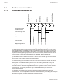 22
22
-
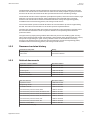 23
23
-
 24
24
-
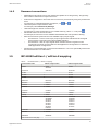 25
25
-
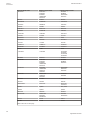 26
26
-
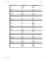 27
27
-
 28
28
-
 29
29
-
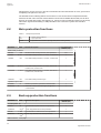 30
30
-
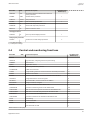 31
31
-
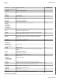 32
32
-
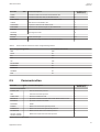 33
33
-
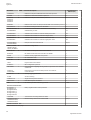 34
34
-
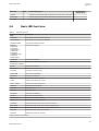 35
35
-
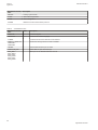 36
36
-
 37
37
-
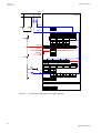 38
38
-
 39
39
-
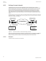 40
40
-
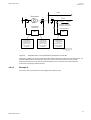 41
41
-
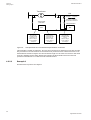 42
42
-
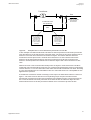 43
43
-
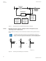 44
44
-
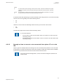 45
45
-
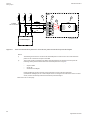 46
46
-
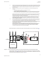 47
47
-
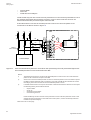 48
48
-
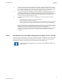 49
49
-
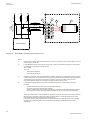 50
50
-
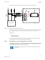 51
51
-
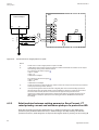 52
52
-
 53
53
-
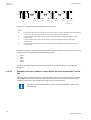 54
54
-
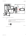 55
55
-
 56
56
-
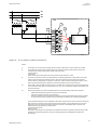 57
57
-
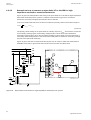 58
58
-
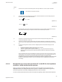 59
59
-
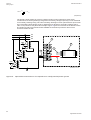 60
60
-
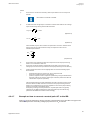 61
61
-
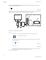 62
62
-
 63
63
-
 64
64
-
 65
65
-
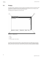 66
66
-
 67
67
-
 68
68
-
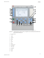 69
69
-
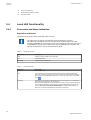 70
70
-
 71
71
-
 72
72
-
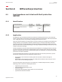 73
73
-
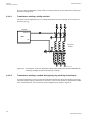 74
74
-
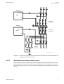 75
75
-
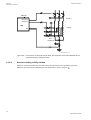 76
76
-
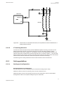 77
77
-
 78
78
-
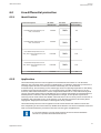 79
79
-
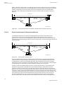 80
80
-
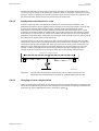 81
81
-
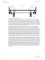 82
82
-
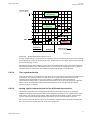 83
83
-
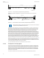 84
84
-
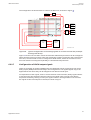 85
85
-
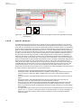 86
86
-
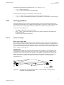 87
87
-
 88
88
-
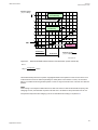 89
89
-
 90
90
-
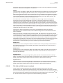 91
91
-
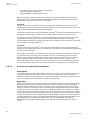 92
92
-
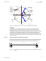 93
93
-
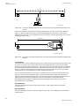 94
94
-
 95
95
-
 96
96
-
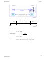 97
97
-
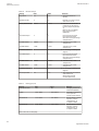 98
98
-
 99
99
-
 100
100
-
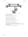 101
101
-
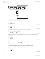 102
102
-
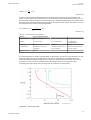 103
103
-
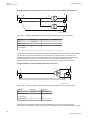 104
104
-
 105
105
-
 106
106
-
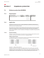 107
107
-
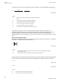 108
108
-
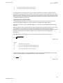 109
109
-
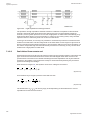 110
110
-
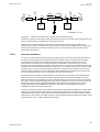 111
111
-
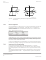 112
112
-
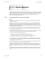 113
113
-
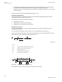 114
114
-
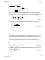 115
115
-
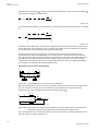 116
116
-
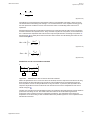 117
117
-
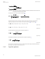 118
118
-
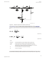 119
119
-
 120
120
-
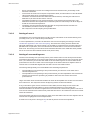 121
121
-
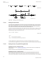 122
122
-
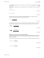 123
123
-
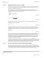 124
124
-
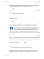 125
125
-
 126
126
-
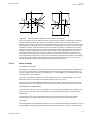 127
127
-
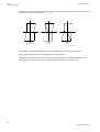 128
128
-
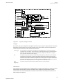 129
129
-
 130
130
-
 131
131
-
 132
132
-
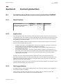 133
133
-
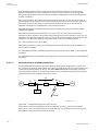 134
134
-
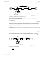 135
135
-
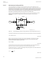 136
136
-
 137
137
-
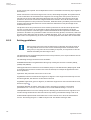 138
138
-
 139
139
-
 140
140
-
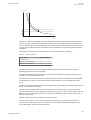 141
141
-
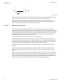 142
142
-
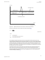 143
143
-
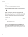 144
144
-
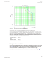 145
145
-
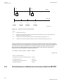 146
146
-
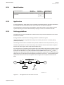 147
147
-
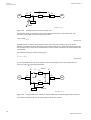 148
148
-
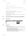 149
149
-
 150
150
-
 151
151
-
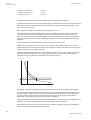 152
152
-
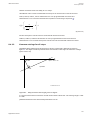 153
153
-
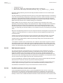 154
154
-
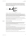 155
155
-
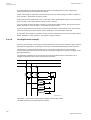 156
156
-
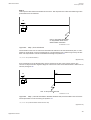 157
157
-
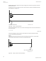 158
158
-
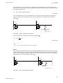 159
159
-
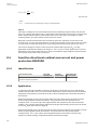 160
160
-
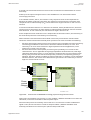 161
161
-
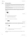 162
162
-
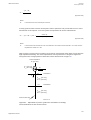 163
163
-
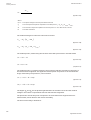 164
164
-
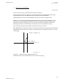 165
165
-
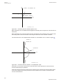 166
166
-
 167
167
-
 168
168
-
 169
169
-
 170
170
-
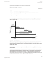 171
171
-
 172
172
-
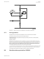 173
173
-
 174
174
-
 175
175
-
 176
176
-
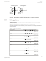 177
177
-
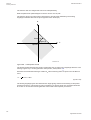 178
178
-
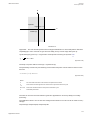 179
179
-
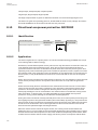 180
180
-
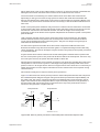 181
181
-
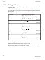 182
182
-
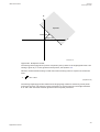 183
183
-
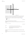 184
184
-
 185
185
-
 186
186
-
 187
187
-
 188
188
-
 189
189
-
 190
190
-
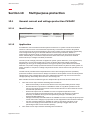 191
191
-
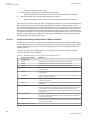 192
192
-
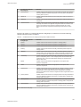 193
193
-
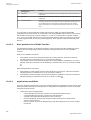 194
194
-
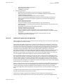 195
195
-
 196
196
-
 197
197
-
 198
198
-
 199
199
-
 200
200
-
 201
201
-
 202
202
-
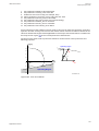 203
203
-
 204
204
-
 205
205
-
 206
206
-
 207
207
-
 208
208
-
 209
209
-
 210
210
-
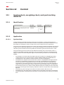 211
211
-
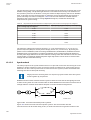 212
212
-
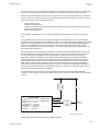 213
213
-
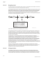 214
214
-
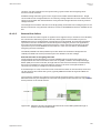 215
215
-
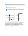 216
216
-
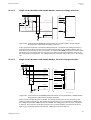 217
217
-
 218
218
-
 219
219
-
 220
220
-
 221
221
-
 222
222
-
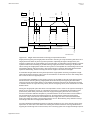 223
223
-
 224
224
-
 225
225
-
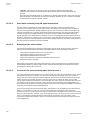 226
226
-
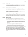 227
227
-
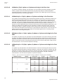 228
228
-
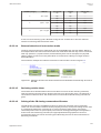 229
229
-
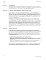 230
230
-
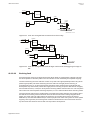 231
231
-
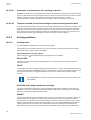 232
232
-
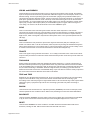 233
233
-
 234
234
-
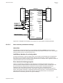 235
235
-
 236
236
-
 237
237
-
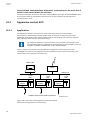 238
238
-
 239
239
-
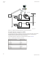 240
240
-
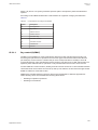 241
241
-
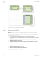 242
242
-
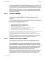 243
243
-
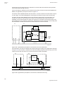 244
244
-
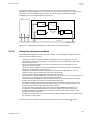 245
245
-
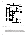 246
246
-
 247
247
-
 248
248
-
 249
249
-
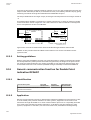 250
250
-
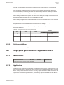 251
251
-
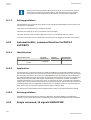 252
252
-
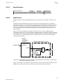 253
253
-
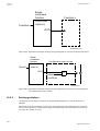 254
254
-
 255
255
-
 256
256
-
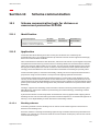 257
257
-
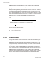 258
258
-
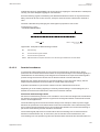 259
259
-
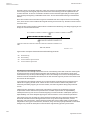 260
260
-
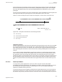 261
261
-
 262
262
-
 263
263
-
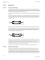 264
264
-
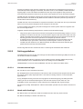 265
265
-
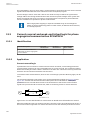 266
266
-
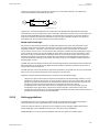 267
267
-
 268
268
-
 269
269
-
 270
270
-
 271
271
-
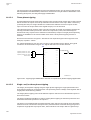 272
272
-
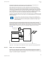 273
273
-
 274
274
-
 275
275
-
 276
276
-
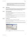 277
277
-
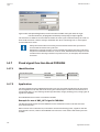 278
278
-
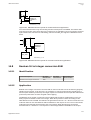 279
279
-
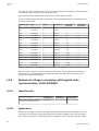 280
280
-
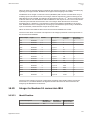 281
281
-
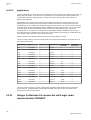 282
282
-
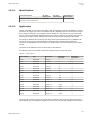 283
283
-
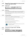 284
284
-
 285
285
-
 286
286
-
 287
287
-
 288
288
-
 289
289
-
 290
290
-
 291
291
-
 292
292
-
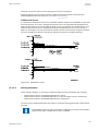 293
293
-
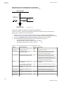 294
294
-
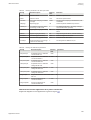 295
295
-
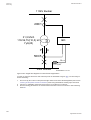 296
296
-
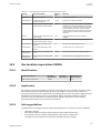 297
297
-
 298
298
-
 299
299
-
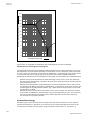 300
300
-
 301
301
-
 302
302
-
 303
303
-
 304
304
-
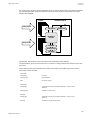 305
305
-
 306
306
-
 307
307
-
 308
308
-
 309
309
-
 310
310
-
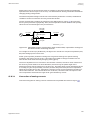 311
311
-
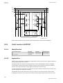 312
312
-
 313
313
-
 314
314
-
 315
315
-
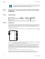 316
316
-
 317
317
-
 318
318
-
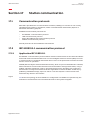 319
319
-
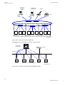 320
320
-
 321
321
-
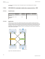 322
322
-
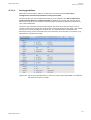 323
323
-
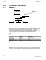 324
324
-
 325
325
-
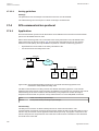 326
326
-
 327
327
-
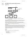 328
328
-
 329
329
-
 330
330
-
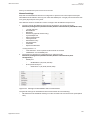 331
331
-
 332
332
-
 333
333
-
 334
334
-
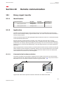 335
335
-
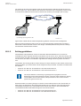 336
336
-
 337
337
-
 338
338
-
 339
339
-
 340
340
-
 341
341
-
 342
342
-
 343
343
-
 344
344
-
 345
345
-
 346
346
-
 347
347
-
 348
348
-
 349
349
-
 350
350
-
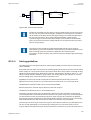 351
351
-
 352
352
-
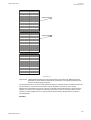 353
353
-
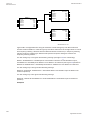 354
354
-
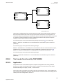 355
355
-
 356
356
-
 357
357
-
 358
358
-
 359
359
-
 360
360
-
 361
361
-
 362
362
-
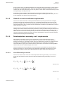 363
363
-
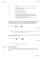 364
364
-
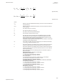 365
365
-
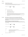 366
366
-
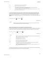 367
367
-
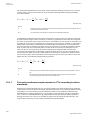 368
368
-
 369
369
-
 370
370
-
 371
371
-
 372
372
-
 373
373
-
 374
374
-
 375
375
-
 376
376
-
 377
377
-
 378
378
-
 379
379
-
 380
380
-
 381
381
-
 382
382


ABB RED650 Applications Manual
- Tipo
- Applications Manual
- Questo manuale è adatto anche per
in altre lingue
- English: ABB RED650
Documenti correlati
-
ABB RED650 Applications Manual
-
ABB REL650 series Applications Manual
-
-
ABB Relion 615 series Engineering Manual
-
ABB Relion REC615 Istruzioni per l'uso
-
-
-
ABB HD4-HPA Series Installation And Service Instructions Manual
Altri documenti
-
IFM DF2208 Istruzioni per l'uso
-
Omron VS MINI J7 Manuale del proprietario
-
General Monitors TA402A Single Channel Trip Amplifier Manuale del proprietario
-
WAGO ETHERNET Controller /XTR Manuale utente
-
 Allen-Bradley PowerFlex 70 Guida d'installazione
-
 Contrel ELR-4C Manuale utente
-
IK Multimedia irig mic cast Manuale utente
-
Eaton JDB Installation Instructions Manual
-
IK Multimedia iRig Keys Pro Manuale utente
-

