
Relion
®
650 series
Line distance protection REL650 ANSI
Application manual


Document ID: 1MRK 506 334-UUS
Issued: October 2016
Revision: A
Product version: 1.3
© Copyright 2013 ABB. All rights reserved

Copyright
This document and parts thereof must not be reproduced or copied without written
permission from ABB, and the contents thereof must not be imparted to a third party, nor
used for any unauthorized purpose.
The software and hardware described in this document is furnished under a license and
may be used or disclosed only in accordance with the terms of such license.
This product includes software developed by the OpenSSL Project for use in the OpenSSL
Toolkit. (http://www.openssl.org/)
This product includes cryptographic software written/developed by: Eric Young
([email protected]) and Tim Hudson ([email protected]).
Trademarks
ABB and Relion are registered trademarks of the ABB Group. All other brand or product
names mentioned in this document may be trademarks or registered trademarks of their
respective holders.
Warranty
Please inquire about the terms of warranty from your nearest ABB representative.
ABB AB
Grid Automation Products
SE-721 59 Västerås
Sweden
Telephone: +46 (0) 21 32 50 00
Facsimile: +46 (0) 21 14 69 18
http://www.abb.com/protection-control

Disclaimer
The data, examples and diagrams in this manual are included solely for the concept or
product description and are not to be deemed as a statement of guaranteed properties. All
persons responsible for applying the equipment addressed in this manual must satisfy
themselves that each intended application is suitable and acceptable, including that any
applicable safety or other operational requirements are complied with. In particular, any
risks in applications where a system failure and/or product failure would create a risk for
harm to property or persons (including but not limited to personal injuries or death) shall
be the sole responsibility of the person or entity applying the equipment, and those so
responsible are hereby requested to ensure that all measures are taken to exclude or
mitigate such risks.
This document has been carefully checked by ABB but deviations cannot be completely
ruled out. In case any errors are detected, the reader is kindly requested to notify the
manufacturer. Other than under explicit contractual commitments, in no event shall ABB
be responsible or liable for any loss or damage resulting from the use of this manual or the
application of the equipment.

Conformity
This
product complies with the directive of the Council of the European Communities on
the approximation of the laws of the Member States relating to electromagnetic
compatibility (EMC Directive 2004/108/EC) and concerning electrical equipment for use
within specified voltage limits (Low-voltage directive 2006/95/EC). This conformity is
the result of tests conducted by ABB in accordance with the product standard EN
60255-26 for the EMC directive, and with the product standards EN 60255-1 and EN
60255-27 for the low voltage directive. The product is designed in accordance with the
international standards of the IEC 60255 series and ANSI C37.90.

Table of contents
Section 1 Introduction..........................................................................19
This manual............................................................................................ 19
Intended audience.................................................................................. 19
Product documentation...........................................................................20
Product documentation set................................................................20
Document revision history................................................................. 21
Related documents............................................................................21
Symbols and conventions.......................................................................22
Symbols.............................................................................................22
Document conventions...................................................................... 23
Section 2 Application...........................................................................25
REL650 application.................................................................................25
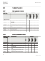
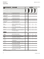
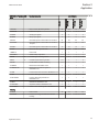
Available functions..................................................................................30
Main protection functions...................................................................30
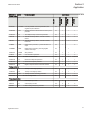
Back-up protection functions............................................................. 30
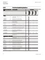
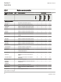
Control and monitoring functions.......................................................32
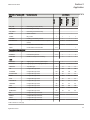
Station communication...................................................................... 36
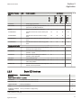
Basic IED functions........................................................................... 37
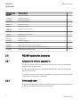
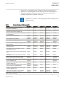
REL650 application examples................................................................ 38
Adaptation to different applications................................................... 38
Functionality table..............................................................................38
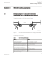
Section 3 REL650 setting examples................................................... 41
Setting example for a two-ended overhead transmission line in a
solidly grounded network........................................................................ 41
Calculating general settings for analogue TRM inputs 4I 1I 5U........ 42
Calculating settings for Global base values for setting function
GBASVAL..........................................................................................43
Calculating settings for five zone distance protection,
quadrilateral and mho characteristic ZQMPDIS (21).........................44
Calculating general settings......................................................... 46
Calculating settings for zone 1..................................................... 47
Calculating settings for zone 2..................................................... 51
Calculating settings for zone 3..................................................... 53
Calculating settings for zone 4..................................................... 54
Table of contents
1
Application manual

Calculating settings for phase selection with load encroachment
FDPSPDIS (21)................................................................................. 55
Faulty phase identification with load encroachment for mho
FMPSPDIS........................................................................................ 57
Calculating settings for scheme communication logic with delta
based blocking scheme signal transmit ZCPSCH (85)......................57
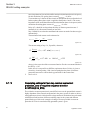
Principles for over-reach permissive communication logic...........58
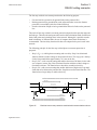
Principles for under-reach permissive communication logic.........59
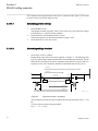
Principle for blocking scheme.......................................................60
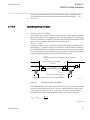
Principle for delta blocking scheme.............................................. 62
Calculating setting for current reversal and weak end infeed logic
for distance protection ZCRWPSCH (85).......................................... 64
Calculating setting for switch into fault logic voltage and current
based ZCVPSOF...............................................................................65
Calculating settings for four step phase overcurrent protection 3-
phase output OC4PTOC 51_67.........................................................66
Calculating general settings......................................................... 67
Calculating settings for step 1...................................................... 68
Calculating settings for step 2...................................................... 68
Calculating settings for step 3...................................................... 69
Calculating settings for four step residual overcurrent protection,
zero or negative sequence direction EF4PTOC(51N_67N)...............70
Calculating general settings......................................................... 72
Calculating settings for step 1...................................................... 72
Calculating settings for step 2...................................................... 73
Calculating settings for step 4...................................................... 74
Calculating settings for scheme communication for residual
overcurrent protection ECPSCH (85)................................................ 74
Over-reach permissive logic ........................................................ 75
Under-reach permissive logic ...................................................... 76
Blocking scheme.......................................................................... 78
Calculating settings for current reversal and weak-end infeed
logic for residual overcurrent protection ECRWPSCH (85)............... 79
Calculating settings for breaker failure protection 3-phase
activation and output CCRBRF (50BF)............................................. 81
Setting example for a two-ended over-head transmission line in a
high impedance network.........................................................................82
Calculating settings for phase preference logic PPLPHIZ.................83
Calculating settings for sensitive directional residual overcurrent
protection SDEPSDE 67N................................................................. 85
Section 4 Analog inputs.......................................................................89
Table of contents
2
Application manual

Introduction............................................................................................. 89
Setting guidelines................................................................................... 89
Setting of the phase reference channel.............................................89
Relationships between setting parameter Base Current, CT rated
primary current and minimum pickup of a protection IED..................90
Setting of current channels................................................................90
Example 1.....................................................................................91
Example 2.....................................................................................92
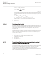
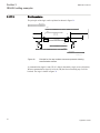
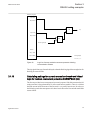
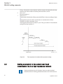
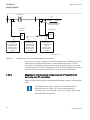
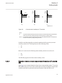
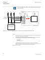
Examples on how to connect, configure and set CT inputs for
most commonly used CT connections..........................................94
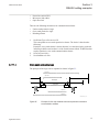
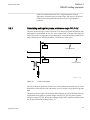
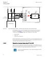
Example on how to connect a wye connected three-phase CT
set to the IED................................................................................95
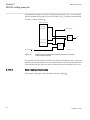
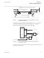
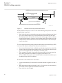
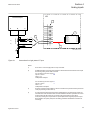
Example how to connect single-phase CT to the IED.................. 98
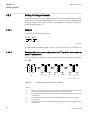
Setting of voltage channels............................................................. 100
Example......................................................................................100
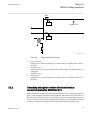
Examples how to connect, configure and set VT inputs for
most commonly used VT connections........................................100
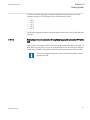
Examples on how to connect a three phase-to-ground
connected VT to the IED............................................................ 101
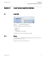
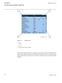
Section 5 Local human-machine interface........................................ 105
Local HMI..............................................................................................105
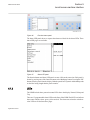
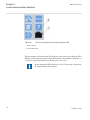
Display.............................................................................................105
LEDs................................................................................................107
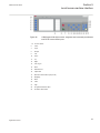
Keypad............................................................................................ 108
Local HMI functionality.................................................................... 110
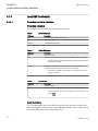
Protection and alarm indication.................................................. 110
Parameter management ............................................................111
Front communication.................................................................. 111
Section 6 Impedance protection........................................................113
Five zone distance protection, quadrilateral and mho characteristic
ZQMPDIS (21)...................................................................................... 113
Identification.................................................................................... 113
Application....................................................................................... 113
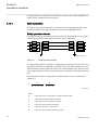
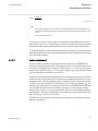
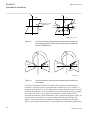
System grounding.......................................................................114
Fault infeed from remote end..................................................... 117
Short line application.................................................................. 118
Long transmission line application..............................................119
Parallel line application with mutual coupling............................. 120
Tapped line application...............................................................125
Table of contents
3
Application manual

Load encroachment....................................................................127
Setting guidelines............................................................................ 129
General.......................................................................................129
Setting of characteristic.............................................................. 130
Quadrilateral characteristics....................................................... 136
Mho characteristics.....................................................................138
Phase selection with load enchroachment, quadrilateral
characteristic FDPSPDIS (21).............................................................. 139
Identification.................................................................................... 139
Application....................................................................................... 139
Setting guidelines............................................................................ 139
Load encroachment characteristics............................................139
Resistive reach with load encroachment characteristic..............145
Minimum operate currents..........................................................146
Faulty phase identification with load enchroachment for mho
FMPSPDIS (21).................................................................................... 146
Identification.................................................................................... 146
Application....................................................................................... 146
Setting guidelines............................................................................ 147
Load encroachment....................................................................148
Additional distance protection directional function for ground faults
ZDARDIR (21D)....................................................................................149
Identification.................................................................................... 149
FunctionalityApplication...................................................................150
Setting guidelines............................................................................ 150
Phase preference logic PPLPHIZ......................................................... 152
Identification.................................................................................... 152
Application....................................................................................... 152
Setting guidelines............................................................................ 156
Power swing detection ZMRPSB (68).................................................. 157
Identification.................................................................................... 157
Application....................................................................................... 157
General.......................................................................................157
Basic characteristics...................................................................158
Setting guidelines............................................................................ 158
Automatic switch onto fault logic, voltage and current based
ZCVPSOF.............................................................................................166
Identification.................................................................................... 166
Application....................................................................................... 166
Setting guidelines............................................................................ 167
Table of contents
4
Application manual

Section 7 Current protection..............................................................169
Instantaneous phase overcurrent protection 3-phase output
PHPIOC (50).........................................................................................169
Identification.................................................................................... 169
Application....................................................................................... 169
Setting guidelines............................................................................ 170
Meshed network without parallel line..........................................170
Meshed network with parallel line...............................................172
Instantaneous phase overcurrent protection phase segregated
output SPTPIOC (50)............................................................................174
Identification.................................................................................... 174
Application....................................................................................... 174
Setting guidelines............................................................................ 174
Meshed network without parallel line..........................................175
Meshed network with parallel line...............................................177
Four step phase overcurrent protection 3-phase output OC4PTOC
(51/67).................................................................................................. 179
Identification.................................................................................... 179
Application....................................................................................... 179
Setting guidelines............................................................................ 180
Settings for steps 1 to 4 .............................................................181
2nd harmonic restrain.................................................................183
Four step phase overcurrent protection phase segregated output
OC4SPTOC 51_67............................................................................... 189
Identification.................................................................................... 189
Application....................................................................................... 189
Setting guidelines............................................................................ 190
Settings for steps 1 to 4..............................................................192
2nd harmonic restrain.................................................................194
Example......................................................................................197
Instantaneous residual overcurrent protection EFPIOC (50N)............. 199
Identification.................................................................................... 199
Application....................................................................................... 199
Setting guidelines............................................................................ 199
Four step residual overcurrent protection, zero, negative sequence
direction EF4PTOC (51N/67N)............................................................. 202
Identification.................................................................................... 202
Application....................................................................................... 202
Setting guidelines............................................................................ 204
Settings for steps 1 and 4 ..........................................................205
Table of contents
5
Application manual

Common settings for all steps.................................................... 206
2nd harmonic restrain.................................................................208
Line application example1.......................................................... 208
Sensitive directional residual overcurrent and power protection
SDEPSDE (67N)...................................................................................214
Identification.................................................................................... 214
Application....................................................................................... 214
Setting guidelines............................................................................ 216
Time delayed 2-step undercurrent protection UC2PTUC (37)..............224
Identification.................................................................................... 224
Application....................................................................................... 224
Setting guidelines............................................................................ 226
Thermal overload protection, one time constant Fahrenheit/Celsius
LFPTTR/LCPTTR (26)..........................................................................227
Identification.................................................................................... 227
Application....................................................................................... 227
Setting guidelines............................................................................ 228
Breaker failure protection 3-phase activation and output CCRBRF (
50BF).................................................................................................... 229
Identification.................................................................................... 229
Application....................................................................................... 229
Setting guidelines............................................................................ 230
Breaker failure protection phase segregated activation and output
CSPRBRF (50BF).................................................................................233
Identification.................................................................................... 233
Application....................................................................................... 233
Setting guidelines............................................................................ 234
Stub protection STBPTOC (50STB)..................................................... 237
Identification.................................................................................... 237
Application....................................................................................... 237
Setting guidelines............................................................................ 238
Pole discrepancy protection CCRPLD (52PD)..................................... 239
Identification.................................................................................... 239
Application....................................................................................... 239
Setting guidelines............................................................................ 240
Broken conductor check BRCPTOC (46)............................................. 240
Identification.................................................................................... 240
Application....................................................................................... 240
Setting guidelines............................................................................ 241
Directional over-/under-power protection GOPPDOP/GUPPDUP
(32/37).................................................................................................. 241
Table of contents
6
Application manual

Application....................................................................................... 241
Directional overpower protection GOPPDOP (32).......................... 243
Identification............................................................................... 244
Setting guidelines....................................................................... 244
Directional underpower protection GUPPDUP (37).........................248
Identification............................................................................... 248
Setting guidelines....................................................................... 248
Negative sequence based overcurrent function DNSPTOC (46)......... 252
Identification.................................................................................... 252
Application....................................................................................... 252
Setting guidelines............................................................................ 252
Section 8 Voltage protection............................................................. 255
Two step undervoltage protection UV2PTUV (27)................................255
Identification.................................................................................... 255
Application....................................................................................... 255
Setting guidelines............................................................................ 256
Equipment protection, such as for motors and generators.........256
Disconnected equipment detection............................................ 256
Power supply quality ..................................................................256
Voltage instability mitigation....................................................... 257
Backup protection for power system faults.................................257
Settings for Two step undervoltage protection........................... 257
Two step overvoltage protection OV2PTOV (59)................................. 258
Identification.................................................................................... 258
Application....................................................................................... 259
Setting guidelines............................................................................ 259
Two step residual overvoltage protection ROV2PTOV (59N)...............262
Identification.................................................................................... 262
Application....................................................................................... 262
Setting guidelines............................................................................ 262
Power supply quality...................................................................263
High impedance grounded systems........................................... 263
Direct grounded system..............................................................264
Settings for Two step residual overvoltage protection................265
Loss of voltage check LOVPTUV (27).................................................. 267
Identification.................................................................................... 267
Application....................................................................................... 267
Setting guidelines............................................................................ 267
Advanced users settings................................................................. 267
Table of contents
7
Application manual

Section 9 Frequency protection.........................................................269
Underfrequency protection SAPTUF (81).............................................269
Identification.................................................................................... 269
Application....................................................................................... 269
Setting guidelines............................................................................ 270
Overfrequency protection SAPTOF (81)...............................................270
Identification.................................................................................... 271
Application....................................................................................... 271
Setting guidelines............................................................................ 271
Rate-of-change frequency protection SAPFRC (81)............................ 272
Identification.................................................................................... 272
Application....................................................................................... 272
Setting guidelines............................................................................ 273
Section 10 Secondary system supervision..........................................275
Current circuit supervision CCSRDIF (87)............................................275
Identification.................................................................................... 275
Application....................................................................................... 275
Setting guidelines............................................................................ 276
Fuse failure supervision SDDRFUF......................................................276
Identification.................................................................................... 276
Application....................................................................................... 276
Setting guidelines............................................................................ 277
General.......................................................................................277
Setting of common parameters.................................................. 277
Negative sequence based.......................................................... 278
Zero sequence based.................................................................279
Delta V and delta I ..................................................................... 280
Dead line detection.....................................................................280
Breaker close/trip circuit monitoring TCSSCBR................................... 281
Identification.................................................................................... 281
Application....................................................................................... 281
Section 11 Control...............................................................................287
Synchronism check, energizing check, and synchronizing
SESRSYN (25)..................................................................................... 287
Identification.................................................................................... 287
Application....................................................................................... 287
Synchronizing............................................................................. 287
Synchronism check.................................................................... 288
Table of contents
8
Application manual

Energizing check........................................................................ 290
Voltage selection........................................................................ 291
External fuse failure....................................................................292
Application examples.......................................................................293
Single circuit breaker with single busbar.................................... 294
Single circuit breaker with double busbar, external voltage
selection..................................................................................... 295
Single circuit breaker with double busbar, internal voltage
selection..................................................................................... 296
Double circuit breaker.................................................................297
Setting guidelines............................................................................ 298
Autorecloser for 3-phase operation SMBRREC (79)............................ 303
Identification ................................................................................... 303
Application....................................................................................... 303
Auto-reclosing operation OFF and ON....................................... 306
Initiate auto-reclosing and conditions for initiation of a
reclosing cycle............................................................................ 306
Initiate auto-reclosing from CB open information....................... 307
Blocking of the autorecloser....................................................... 307
Control of the auto-reclosing open time .....................................307
Long trip signal........................................................................... 307
Maximum number of reclosing shots..........................................308
3-phase reclosing, one to five shots according to setting
NoOfShots.................................................................................. 308
Reclosing reset timer..................................................................308
Transient fault.............................................................................308
Permanent fault and reclosing unsuccessful signal....................308
Lock-out initiation........................................................................309
Automatic continuation of the reclosing sequence .................... 310
Thermal overload protection holding the auto-reclosing
function back ............................................................................. 311
Setting guidelines............................................................................ 311
Configuration.............................................................................. 311
Auto-recloser parameter settings............................................... 314
Autorecloser for 1/3-phase operation STBRREC (79)..........................317
Identification.................................................................................... 317
Application....................................................................................... 317
Auto-reclosing operation Disabled and Enabled........................ 321
Initiate auto-reclosing and conditions for initiation of a
reclosing cycle............................................................................ 321
Initiate auto-reclosing from CB open information....................... 322
Table of contents
9
Application manual

Blocking of the autorecloser....................................................... 322
Control of the auto-reclosing open time for shot 1......................323
Long trip signal........................................................................... 323
Reclosing programs....................................................................323
FirstShot=3ph (normal setting for a single 3 phase shot)...........323
3-phase reclosing, one to five shots according to setting
NoOfShots.................................................................................. 324
FirstShot=1ph 1-phase reclosing in the first shot....................... 324
FirstShot=1ph + 1*3ph 1-phase or 3-phase reclosing in the
first shot...................................................................................... 324
FirstShot=1ph + 1*2/3ph 1-phase, 2-phase or 3-phase
reclosing in the first shot.............................................................325
Evolving fault.............................................................................. 325
Reclosing reset timer..................................................................325
Transient fault.............................................................................326
Permanent fault and reclosing unsuccessful signal....................326
Lock-out initiation........................................................................326
Automatic continuation of the reclosing sequence..................... 327
Thermal overload protection holding the auto-reclosing
function back.............................................................................. 328
Setting guidelines............................................................................ 328
Configuration.............................................................................. 328
Recommendations for input signals........................................... 328
STBRREC- Auto-recloser parameter settings............................ 332
Apparatus control .................................................................................335
Identification.................................................................................... 335
Application....................................................................................... 335
Interaction between modules...........................................................342
Setting guidelines............................................................................ 345
Switch controller (SCSWI).......................................................... 345
Bay control (QCBAY)..................................................................345
Interlocking........................................................................................... 346
Identification.................................................................................... 346
Application....................................................................................... 346
Configuration guidelines.................................................................. 347
Interlocking for busbar grounding switch BB_ES (3)....................... 348
Application.................................................................................. 348
Signals in single breaker arrangement....................................... 348
Signals in double-breaker arrangement..................................... 354
Signals in breaker and a half arrangement.................................355
Table of contents
10
Application manual

Interlocking for bus-section breaker A1A2_BS (3)...........................355
Application.................................................................................. 355
Signals from all feeders.............................................................. 356
Configuration setting...................................................................359
Interlocking for bus-section disconnector A1A2_DC (3).................. 360
Application.................................................................................. 360
Signals in single breaker arrangement....................................... 360
Signals in double-breaker arrangement..................................... 364
Signals in breaker and a half arrangement.................................366
Interlocking for bus-coupler bay ABC_BC (3)..................................367
Application.................................................................................. 367
Configuration.............................................................................. 368
Signals from all feeders.............................................................. 368
Signals from bus-coupler............................................................371
Configuration setting...................................................................372
Interlocking for breaker-and-a-half diameter BH (3)........................ 373
Application.................................................................................. 373
Configuration setting...................................................................374
Interlocking for double CB bay DB (3)............................................. 375
Application.................................................................................. 375
Configuration setting...................................................................376
Interlocking for line bay ABC_LINE (3)............................................ 377
Application.................................................................................. 377
Signals from bypass busbar....................................................... 378
Signals from bus-coupler............................................................379
Configuration setting...................................................................382
Interlocking for transformer bay AB_TRAFO (3)..............................383
Application.................................................................................. 383
Signals from bus-coupler............................................................383
Configuration setting...................................................................384
Logic rotating switch for function selection and LHMI presentation
SLGGIO................................................................................................ 385
Identification.................................................................................... 385
Application....................................................................................... 385
Setting guidelines............................................................................ 386
Selector mini switch VSGGIO...............................................................386
Identification.................................................................................... 386
Application....................................................................................... 386
Setting guidelines............................................................................ 387
IEC61850 generic communication I/O functions DPGGIO................... 387
Table of contents
11
Application manual

Identification.................................................................................... 387
Application....................................................................................... 388
Setting guidelines............................................................................ 388
Single point generic control 8 signals SPC8GGIO............................... 388
Identification.................................................................................... 388
Application....................................................................................... 388
Setting guidelines............................................................................ 388
Automation bits AUTOBITS.................................................................. 389
Identification.................................................................................... 389
Application....................................................................................... 389
Setting guidelines............................................................................ 389
Section 12 Scheme communication.................................................... 391
Scheme communication logic with delta based blocking scheme
signal transmit ZCPSCH(85)................................................................ 391
Identification.................................................................................... 391
Application....................................................................................... 391
Blocking schemes.......................................................................392
Permissive schemes...................................................................394
Intertrip scheme..........................................................................397
Setting guidelines............................................................................ 397
Blocking scheme........................................................................ 397
Delta blocking scheme............................................................... 398
Permissive underreaching scheme............................................ 398
Permissive overreaching scheme...............................................398
Unblocking scheme.................................................................... 399
Intertrip scheme..........................................................................399
Current reversal and WEI logic for distance protection 3-phase
ZCRWPSCH (85)..................................................................................399
Identification.................................................................................... 399
Application....................................................................................... 399
Current reversal logic................................................................. 399
Weak-end infeed logic................................................................ 400
Setting guidelines............................................................................ 401
Current reversal logic................................................................. 401
Weak-end infeed logic................................................................ 402
Current reversal and WEI logic for distance protection, phase
segregated ZCWSPSCH (85)...............................................................402
Identification.................................................................................... 402
Application....................................................................................... 402
Current reversal logic................................................................. 402
Table of contents
12
Application manual

Weak-end infeed logic................................................................ 403
Setting guidelines............................................................................ 404
Current reverse logic.................................................................. 404
Weak-end infeed logic................................................................ 405
Local acceleration logic ZCLCPLAL..................................................... 405
Identification.................................................................................... 405
Application....................................................................................... 405
Setting guidelines............................................................................ 406
Scheme communication logic for residual overcurrent protection
ECPSCH (85)....................................................................................... 407
Identification.................................................................................... 407
Application....................................................................................... 407
Setting guidelines............................................................................ 408
Current reversal and weak-end infeed logic for residual overcurrent
protection ECRWPSCH (85).................................................................408
Identification.................................................................................... 408
Application....................................................................................... 409
Fault current reversal logic......................................................... 409
Weak-end infeed logic................................................................ 410
Setting guidelines............................................................................ 410
Current reversal..........................................................................410
Weak-end infeed........................................................................ 411
Section 13 Logic..................................................................................413
Tripping logic common 3-phase output SMPPTRC (94).......................413
Identification.................................................................................... 413
Application....................................................................................... 413
Three-pole tripping .................................................................... 413
Lock-out......................................................................................414
Blocking of the function block..................................................... 414
Setting guidelines............................................................................ 415
Tripping logic phase segregated output SPTPTRC 94.........................415
Identification.................................................................................... 415
Application....................................................................................... 415
Single- and/or three-pole tripping............................................... 416
Lock out...................................................................................... 417
Blocking of the function block..................................................... 417
Setting guidelines............................................................................ 417
Trip matrix logic TMAGGIO.................................................................. 418
Identification.................................................................................... 418
Table of contents
13
Application manual

Application....................................................................................... 418
Setting guidelines............................................................................ 419
Configurable logic blocks......................................................................419
Identification.................................................................................... 419
Application....................................................................................... 420
Configuration.............................................................................. 421
Fixed signals FXDSIGN........................................................................422
Identification.................................................................................... 422
Application....................................................................................... 422
Boolean 16 to integer conversion B16I.................................................423
Identification.................................................................................... 423
Application....................................................................................... 423
Setting guidelines............................................................................ 424
Boolean 16 to integer conversion with logic node representation
B16IFCVI.............................................................................................. 424
Identification.................................................................................... 424
Application....................................................................................... 424
Setting guidelines............................................................................ 424
Integer to boolean 16 conversion IB16A...............................................424
Identification.................................................................................... 424
Application....................................................................................... 425
Setting guidelines............................................................................ 425
Integer to boolean 16 conversion with logic node representation
IB16FCVB.............................................................................................425
Identification.................................................................................... 425
Application....................................................................................... 425
Settings............................................................................................425
Elapsed time integrator with limit transgression and overflow
supervision TEIGGIO............................................................................426
Identification.................................................................................... 426
Application....................................................................................... 426
Setting guidelines............................................................................ 426
Section 14 Monitoring..........................................................................427
IEC61850 generic communication I/O functions SPGGIO................... 427
Identification.................................................................................... 427
Application....................................................................................... 427
Setting guidelines............................................................................ 427
IEC61850 generic communication I/O functions 16 inputs SP16GGIO427
Identification.................................................................................... 427
Application....................................................................................... 428
Table of contents
14
Application manual
La pagina si sta caricando...
La pagina si sta caricando...
La pagina si sta caricando...
La pagina si sta caricando...
La pagina si sta caricando...
La pagina si sta caricando...
La pagina si sta caricando...
La pagina si sta caricando...
La pagina si sta caricando...
La pagina si sta caricando...
La pagina si sta caricando...
La pagina si sta caricando...
La pagina si sta caricando...
La pagina si sta caricando...
La pagina si sta caricando...
La pagina si sta caricando...
La pagina si sta caricando...
La pagina si sta caricando...
La pagina si sta caricando...
La pagina si sta caricando...
La pagina si sta caricando...
La pagina si sta caricando...
La pagina si sta caricando...
La pagina si sta caricando...
La pagina si sta caricando...
La pagina si sta caricando...
La pagina si sta caricando...
La pagina si sta caricando...
La pagina si sta caricando...
La pagina si sta caricando...
La pagina si sta caricando...
La pagina si sta caricando...
La pagina si sta caricando...
La pagina si sta caricando...
La pagina si sta caricando...
La pagina si sta caricando...
La pagina si sta caricando...
La pagina si sta caricando...
La pagina si sta caricando...
La pagina si sta caricando...
La pagina si sta caricando...
La pagina si sta caricando...
La pagina si sta caricando...
La pagina si sta caricando...
La pagina si sta caricando...
La pagina si sta caricando...
La pagina si sta caricando...
La pagina si sta caricando...
La pagina si sta caricando...
La pagina si sta caricando...
La pagina si sta caricando...
La pagina si sta caricando...
La pagina si sta caricando...
La pagina si sta caricando...
La pagina si sta caricando...
La pagina si sta caricando...
La pagina si sta caricando...
La pagina si sta caricando...
La pagina si sta caricando...
La pagina si sta caricando...
La pagina si sta caricando...
La pagina si sta caricando...
La pagina si sta caricando...
La pagina si sta caricando...
La pagina si sta caricando...
La pagina si sta caricando...
La pagina si sta caricando...
La pagina si sta caricando...
La pagina si sta caricando...
La pagina si sta caricando...
La pagina si sta caricando...
La pagina si sta caricando...
La pagina si sta caricando...
La pagina si sta caricando...
La pagina si sta caricando...
La pagina si sta caricando...
La pagina si sta caricando...
La pagina si sta caricando...
La pagina si sta caricando...
La pagina si sta caricando...
La pagina si sta caricando...
La pagina si sta caricando...
La pagina si sta caricando...
La pagina si sta caricando...
La pagina si sta caricando...
La pagina si sta caricando...
La pagina si sta caricando...
La pagina si sta caricando...
La pagina si sta caricando...
La pagina si sta caricando...
La pagina si sta caricando...
La pagina si sta caricando...
La pagina si sta caricando...
La pagina si sta caricando...
La pagina si sta caricando...
La pagina si sta caricando...
La pagina si sta caricando...
La pagina si sta caricando...
La pagina si sta caricando...
La pagina si sta caricando...
La pagina si sta caricando...
La pagina si sta caricando...
La pagina si sta caricando...
La pagina si sta caricando...
La pagina si sta caricando...
La pagina si sta caricando...
La pagina si sta caricando...
La pagina si sta caricando...
La pagina si sta caricando...
La pagina si sta caricando...
La pagina si sta caricando...
La pagina si sta caricando...
La pagina si sta caricando...
La pagina si sta caricando...
La pagina si sta caricando...
La pagina si sta caricando...
La pagina si sta caricando...
La pagina si sta caricando...
La pagina si sta caricando...
La pagina si sta caricando...
La pagina si sta caricando...
La pagina si sta caricando...
La pagina si sta caricando...
La pagina si sta caricando...
La pagina si sta caricando...
La pagina si sta caricando...
La pagina si sta caricando...
La pagina si sta caricando...
La pagina si sta caricando...
La pagina si sta caricando...
La pagina si sta caricando...
La pagina si sta caricando...
La pagina si sta caricando...
La pagina si sta caricando...
La pagina si sta caricando...
La pagina si sta caricando...
La pagina si sta caricando...
La pagina si sta caricando...
La pagina si sta caricando...
La pagina si sta caricando...
La pagina si sta caricando...
La pagina si sta caricando...
La pagina si sta caricando...
La pagina si sta caricando...
La pagina si sta caricando...
La pagina si sta caricando...
La pagina si sta caricando...
La pagina si sta caricando...
La pagina si sta caricando...
La pagina si sta caricando...
La pagina si sta caricando...
La pagina si sta caricando...
La pagina si sta caricando...
La pagina si sta caricando...
La pagina si sta caricando...
La pagina si sta caricando...
La pagina si sta caricando...
La pagina si sta caricando...
La pagina si sta caricando...
La pagina si sta caricando...
La pagina si sta caricando...
La pagina si sta caricando...
La pagina si sta caricando...
La pagina si sta caricando...
La pagina si sta caricando...
La pagina si sta caricando...
La pagina si sta caricando...
La pagina si sta caricando...
La pagina si sta caricando...
La pagina si sta caricando...
La pagina si sta caricando...
La pagina si sta caricando...
La pagina si sta caricando...
La pagina si sta caricando...
La pagina si sta caricando...
La pagina si sta caricando...
La pagina si sta caricando...
La pagina si sta caricando...
La pagina si sta caricando...
La pagina si sta caricando...
La pagina si sta caricando...
La pagina si sta caricando...
La pagina si sta caricando...
La pagina si sta caricando...
La pagina si sta caricando...
La pagina si sta caricando...
La pagina si sta caricando...
La pagina si sta caricando...
La pagina si sta caricando...
La pagina si sta caricando...
La pagina si sta caricando...
La pagina si sta caricando...
La pagina si sta caricando...
La pagina si sta caricando...
La pagina si sta caricando...
La pagina si sta caricando...
La pagina si sta caricando...
La pagina si sta caricando...
La pagina si sta caricando...
La pagina si sta caricando...
La pagina si sta caricando...
La pagina si sta caricando...
La pagina si sta caricando...
La pagina si sta caricando...
La pagina si sta caricando...
La pagina si sta caricando...
La pagina si sta caricando...
La pagina si sta caricando...
La pagina si sta caricando...
La pagina si sta caricando...
La pagina si sta caricando...
La pagina si sta caricando...
La pagina si sta caricando...
La pagina si sta caricando...
La pagina si sta caricando...
La pagina si sta caricando...
La pagina si sta caricando...
La pagina si sta caricando...
La pagina si sta caricando...
La pagina si sta caricando...
La pagina si sta caricando...
La pagina si sta caricando...
La pagina si sta caricando...
La pagina si sta caricando...
La pagina si sta caricando...
La pagina si sta caricando...
La pagina si sta caricando...
La pagina si sta caricando...
La pagina si sta caricando...
La pagina si sta caricando...
La pagina si sta caricando...
La pagina si sta caricando...
La pagina si sta caricando...
La pagina si sta caricando...
La pagina si sta caricando...
La pagina si sta caricando...
La pagina si sta caricando...
La pagina si sta caricando...
La pagina si sta caricando...
La pagina si sta caricando...
La pagina si sta caricando...
La pagina si sta caricando...
La pagina si sta caricando...
La pagina si sta caricando...
La pagina si sta caricando...
La pagina si sta caricando...
La pagina si sta caricando...
La pagina si sta caricando...
La pagina si sta caricando...
La pagina si sta caricando...
La pagina si sta caricando...
La pagina si sta caricando...
La pagina si sta caricando...
La pagina si sta caricando...
La pagina si sta caricando...
La pagina si sta caricando...
La pagina si sta caricando...
La pagina si sta caricando...
La pagina si sta caricando...
La pagina si sta caricando...
La pagina si sta caricando...
La pagina si sta caricando...
La pagina si sta caricando...
La pagina si sta caricando...
La pagina si sta caricando...
La pagina si sta caricando...
La pagina si sta caricando...
La pagina si sta caricando...
La pagina si sta caricando...
La pagina si sta caricando...
La pagina si sta caricando...
La pagina si sta caricando...
La pagina si sta caricando...
La pagina si sta caricando...
La pagina si sta caricando...
La pagina si sta caricando...
La pagina si sta caricando...
La pagina si sta caricando...
La pagina si sta caricando...
La pagina si sta caricando...
La pagina si sta caricando...
La pagina si sta caricando...
La pagina si sta caricando...
La pagina si sta caricando...
La pagina si sta caricando...
La pagina si sta caricando...
La pagina si sta caricando...
La pagina si sta caricando...
La pagina si sta caricando...
La pagina si sta caricando...
La pagina si sta caricando...
La pagina si sta caricando...
La pagina si sta caricando...
La pagina si sta caricando...
La pagina si sta caricando...
La pagina si sta caricando...
La pagina si sta caricando...
La pagina si sta caricando...
La pagina si sta caricando...
La pagina si sta caricando...
La pagina si sta caricando...
La pagina si sta caricando...
La pagina si sta caricando...
La pagina si sta caricando...
La pagina si sta caricando...
La pagina si sta caricando...
La pagina si sta caricando...
La pagina si sta caricando...
La pagina si sta caricando...
La pagina si sta caricando...
La pagina si sta caricando...
La pagina si sta caricando...
La pagina si sta caricando...
La pagina si sta caricando...
La pagina si sta caricando...
La pagina si sta caricando...
La pagina si sta caricando...
La pagina si sta caricando...
La pagina si sta caricando...
La pagina si sta caricando...
La pagina si sta caricando...
La pagina si sta caricando...
La pagina si sta caricando...
La pagina si sta caricando...
La pagina si sta caricando...
La pagina si sta caricando...
La pagina si sta caricando...
La pagina si sta caricando...
La pagina si sta caricando...
La pagina si sta caricando...
La pagina si sta caricando...
La pagina si sta caricando...
La pagina si sta caricando...
La pagina si sta caricando...
La pagina si sta caricando...
La pagina si sta caricando...
La pagina si sta caricando...
La pagina si sta caricando...
La pagina si sta caricando...
La pagina si sta caricando...
La pagina si sta caricando...
La pagina si sta caricando...
La pagina si sta caricando...
La pagina si sta caricando...
La pagina si sta caricando...
La pagina si sta caricando...
La pagina si sta caricando...
La pagina si sta caricando...
La pagina si sta caricando...
La pagina si sta caricando...
La pagina si sta caricando...
La pagina si sta caricando...
La pagina si sta caricando...
La pagina si sta caricando...
La pagina si sta caricando...
La pagina si sta caricando...
La pagina si sta caricando...
La pagina si sta caricando...
La pagina si sta caricando...
La pagina si sta caricando...
La pagina si sta caricando...
La pagina si sta caricando...
La pagina si sta caricando...
La pagina si sta caricando...
La pagina si sta caricando...
La pagina si sta caricando...
La pagina si sta caricando...
La pagina si sta caricando...
La pagina si sta caricando...
La pagina si sta caricando...
La pagina si sta caricando...
La pagina si sta caricando...
La pagina si sta caricando...
La pagina si sta caricando...
La pagina si sta caricando...
La pagina si sta caricando...
La pagina si sta caricando...
La pagina si sta caricando...
La pagina si sta caricando...
La pagina si sta caricando...
La pagina si sta caricando...
La pagina si sta caricando...
La pagina si sta caricando...
La pagina si sta caricando...
La pagina si sta caricando...
La pagina si sta caricando...
La pagina si sta caricando...
La pagina si sta caricando...
La pagina si sta caricando...
La pagina si sta caricando...
La pagina si sta caricando...
La pagina si sta caricando...
La pagina si sta caricando...
La pagina si sta caricando...
La pagina si sta caricando...
La pagina si sta caricando...
La pagina si sta caricando...
La pagina si sta caricando...
La pagina si sta caricando...
La pagina si sta caricando...
La pagina si sta caricando...
La pagina si sta caricando...
La pagina si sta caricando...
La pagina si sta caricando...
La pagina si sta caricando...
La pagina si sta caricando...
La pagina si sta caricando...
La pagina si sta caricando...
La pagina si sta caricando...
La pagina si sta caricando...
La pagina si sta caricando...
La pagina si sta caricando...
La pagina si sta caricando...
La pagina si sta caricando...
La pagina si sta caricando...
La pagina si sta caricando...
La pagina si sta caricando...
La pagina si sta caricando...
La pagina si sta caricando...
La pagina si sta caricando...
La pagina si sta caricando...
La pagina si sta caricando...
La pagina si sta caricando...
La pagina si sta caricando...
La pagina si sta caricando...
La pagina si sta caricando...
La pagina si sta caricando...
La pagina si sta caricando...
La pagina si sta caricando...
La pagina si sta caricando...
La pagina si sta caricando...
La pagina si sta caricando...
La pagina si sta caricando...
La pagina si sta caricando...
La pagina si sta caricando...
La pagina si sta caricando...
La pagina si sta caricando...
La pagina si sta caricando...
La pagina si sta caricando...
La pagina si sta caricando...
La pagina si sta caricando...
La pagina si sta caricando...
La pagina si sta caricando...
La pagina si sta caricando...
La pagina si sta caricando...
La pagina si sta caricando...
La pagina si sta caricando...
La pagina si sta caricando...
La pagina si sta caricando...
La pagina si sta caricando...
La pagina si sta caricando...
La pagina si sta caricando...
La pagina si sta caricando...
La pagina si sta caricando...
La pagina si sta caricando...
La pagina si sta caricando...
La pagina si sta caricando...
La pagina si sta caricando...
La pagina si sta caricando...
La pagina si sta caricando...
La pagina si sta caricando...
La pagina si sta caricando...
La pagina si sta caricando...
La pagina si sta caricando...
La pagina si sta caricando...
La pagina si sta caricando...
La pagina si sta caricando...
La pagina si sta caricando...
La pagina si sta caricando...
La pagina si sta caricando...
La pagina si sta caricando...
La pagina si sta caricando...
La pagina si sta caricando...
La pagina si sta caricando...
La pagina si sta caricando...
La pagina si sta caricando...
La pagina si sta caricando...
La pagina si sta caricando...
La pagina si sta caricando...
La pagina si sta caricando...
La pagina si sta caricando...
La pagina si sta caricando...
La pagina si sta caricando...
La pagina si sta caricando...
La pagina si sta caricando...
La pagina si sta caricando...
La pagina si sta caricando...
La pagina si sta caricando...
La pagina si sta caricando...
La pagina si sta caricando...
La pagina si sta caricando...
La pagina si sta caricando...
La pagina si sta caricando...
La pagina si sta caricando...
La pagina si sta caricando...
La pagina si sta caricando...
-
 1
1
-
 2
2
-
 3
3
-
 4
4
-
 5
5
-
 6
6
-
 7
7
-
 8
8
-
 9
9
-
 10
10
-
 11
11
-
 12
12
-
 13
13
-
 14
14
-
 15
15
-
 16
16
-
 17
17
-
 18
18
-
 19
19
-
 20
20
-
 21
21
-
 22
22
-
 23
23
-
 24
24
-
 25
25
-
 26
26
-
 27
27
-
 28
28
-
 29
29
-
 30
30
-
 31
31
-
 32
32
-
 33
33
-
 34
34
-
 35
35
-
 36
36
-
 37
37
-
 38
38
-
 39
39
-
 40
40
-
 41
41
-
 42
42
-
 43
43
-
 44
44
-
 45
45
-
 46
46
-
 47
47
-
 48
48
-
 49
49
-
 50
50
-
 51
51
-
 52
52
-
 53
53
-
 54
54
-
 55
55
-
 56
56
-
 57
57
-
 58
58
-
 59
59
-
 60
60
-
 61
61
-
 62
62
-
 63
63
-
 64
64
-
 65
65
-
 66
66
-
 67
67
-
 68
68
-
 69
69
-
 70
70
-
 71
71
-
 72
72
-
 73
73
-
 74
74
-
 75
75
-
 76
76
-
 77
77
-
 78
78
-
 79
79
-
 80
80
-
 81
81
-
 82
82
-
 83
83
-
 84
84
-
 85
85
-
 86
86
-
 87
87
-
 88
88
-
 89
89
-
 90
90
-
 91
91
-
 92
92
-
 93
93
-
 94
94
-
 95
95
-
 96
96
-
 97
97
-
 98
98
-
 99
99
-
 100
100
-
 101
101
-
 102
102
-
 103
103
-
 104
104
-
 105
105
-
 106
106
-
 107
107
-
 108
108
-
 109
109
-
 110
110
-
 111
111
-
 112
112
-
 113
113
-
 114
114
-
 115
115
-
 116
116
-
 117
117
-
 118
118
-
 119
119
-
 120
120
-
 121
121
-
 122
122
-
 123
123
-
 124
124
-
 125
125
-
 126
126
-
 127
127
-
 128
128
-
 129
129
-
 130
130
-
 131
131
-
 132
132
-
 133
133
-
 134
134
-
 135
135
-
 136
136
-
 137
137
-
 138
138
-
 139
139
-
 140
140
-
 141
141
-
 142
142
-
 143
143
-
 144
144
-
 145
145
-
 146
146
-
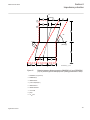 147
147
-
 148
148
-
 149
149
-
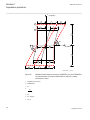 150
150
-
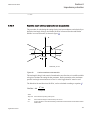 151
151
-
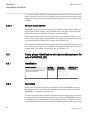 152
152
-
 153
153
-
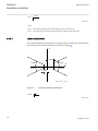 154
154
-
 155
155
-
 156
156
-
 157
157
-
 158
158
-
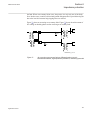 159
159
-
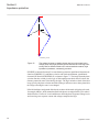 160
160
-
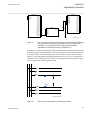 161
161
-
 162
162
-
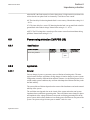 163
163
-
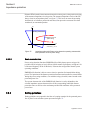 164
164
-
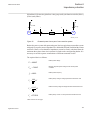 165
165
-
 166
166
-
 167
167
-
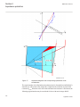 168
168
-
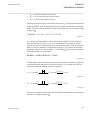 169
169
-
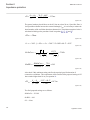 170
170
-
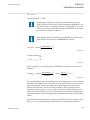 171
171
-
 172
172
-
 173
173
-
 174
174
-
 175
175
-
 176
176
-
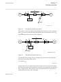 177
177
-
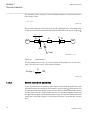 178
178
-
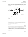 179
179
-
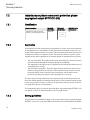 180
180
-
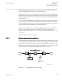 181
181
-
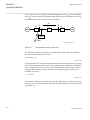 182
182
-
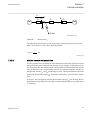 183
183
-
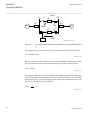 184
184
-
 185
185
-
 186
186
-
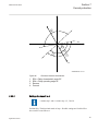 187
187
-
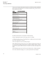 188
188
-
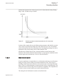 189
189
-
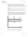 190
190
-
 191
191
-
 192
192
-
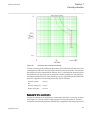 193
193
-
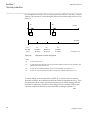 194
194
-
 195
195
-
 196
196
-
 197
197
-
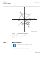 198
198
-
 199
199
-
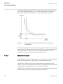 200
200
-
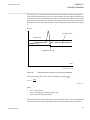 201
201
-
 202
202
-
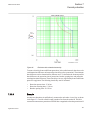 203
203
-
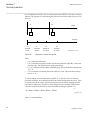 204
204
-
 205
205
-
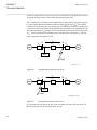 206
206
-
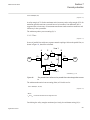 207
207
-
 208
208
-
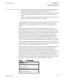 209
209
-
 210
210
-
 211
211
-
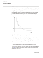 212
212
-
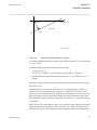 213
213
-
 214
214
-
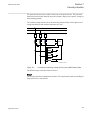 215
215
-
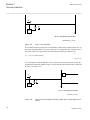 216
216
-
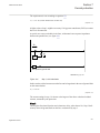 217
217
-
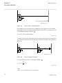 218
218
-
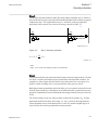 219
219
-
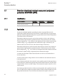 220
220
-
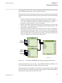 221
221
-
 222
222
-
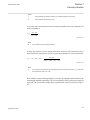 223
223
-
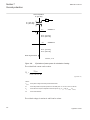 224
224
-
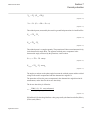 225
225
-
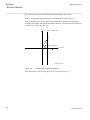 226
226
-
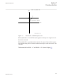 227
227
-
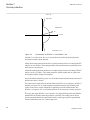 228
228
-
 229
229
-
 230
230
-
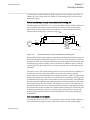 231
231
-
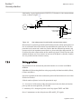 232
232
-
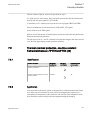 233
233
-
 234
234
-
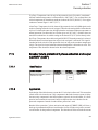 235
235
-
 236
236
-
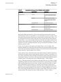 237
237
-
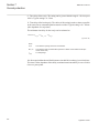 238
238
-
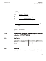 239
239
-
 240
240
-
 241
241
-
 242
242
-
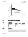 243
243
-
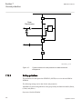 244
244
-
 245
245
-
 246
246
-
 247
247
-
 248
248
-
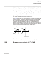 249
249
-
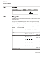 250
250
-
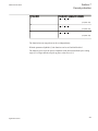 251
251
-
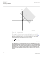 252
252
-
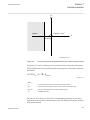 253
253
-
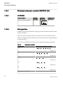 254
254
-
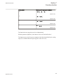 255
255
-
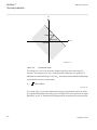 256
256
-
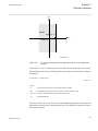 257
257
-
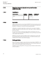 258
258
-
 259
259
-
 260
260
-
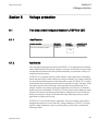 261
261
-
 262
262
-
 263
263
-
 264
264
-
 265
265
-
 266
266
-
 267
267
-
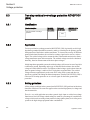 268
268
-
 269
269
-
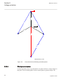 270
270
-
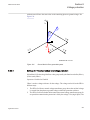 271
271
-
 272
272
-
 273
273
-
 274
274
-
 275
275
-
 276
276
-
 277
277
-
 278
278
-
 279
279
-
 280
280
-
 281
281
-
 282
282
-
 283
283
-
 284
284
-
 285
285
-
 286
286
-
 287
287
-
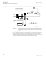 288
288
-
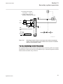 289
289
-
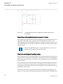 290
290
-
 291
291
-
 292
292
-
 293
293
-
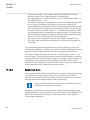 294
294
-
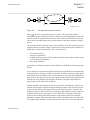 295
295
-
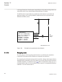 296
296
-
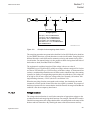 297
297
-
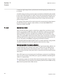 298
298
-
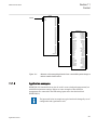 299
299
-
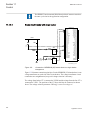 300
300
-
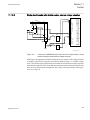 301
301
-
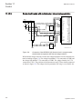 302
302
-
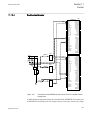 303
303
-
 304
304
-
 305
305
-
 306
306
-
 307
307
-
 308
308
-
 309
309
-
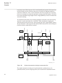 310
310
-
 311
311
-
 312
312
-
 313
313
-
 314
314
-
 315
315
-
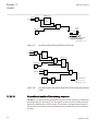 316
316
-
 317
317
-
 318
318
-
 319
319
-
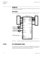 320
320
-
 321
321
-
 322
322
-
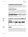 323
323
-
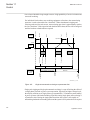 324
324
-
 325
325
-
 326
326
-
 327
327
-
 328
328
-
 329
329
-
 330
330
-
 331
331
-
 332
332
-
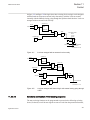 333
333
-
 334
334
-
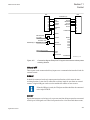 335
335
-
 336
336
-
 337
337
-
 338
338
-
 339
339
-
 340
340
-
 341
341
-
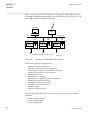 342
342
-
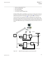 343
343
-
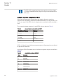 344
344
-
 345
345
-
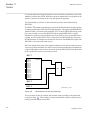 346
346
-
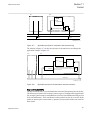 347
347
-
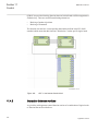 348
348
-
 349
349
-
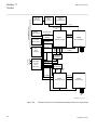 350
350
-
 351
351
-
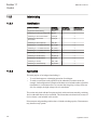 352
352
-
 353
353
-
 354
354
-
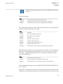 355
355
-
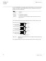 356
356
-
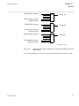 357
357
-
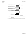 358
358
-
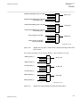 359
359
-
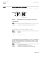 360
360
-
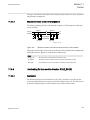 361
361
-
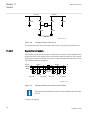 362
362
-
 363
363
-
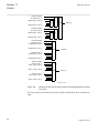 364
364
-
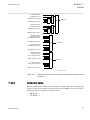 365
365
-
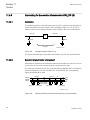 366
366
-
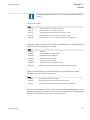 367
367
-
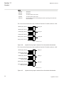 368
368
-
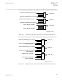 369
369
-
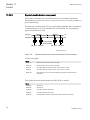 370
370
-
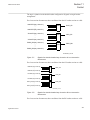 371
371
-
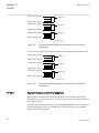 372
372
-
 373
373
-
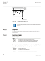 374
374
-
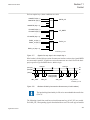 375
375
-
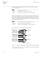 376
376
-
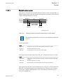 377
377
-
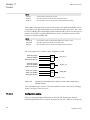 378
378
-
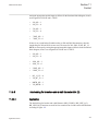 379
379
-
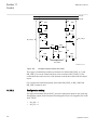 380
380
-
 381
381
-
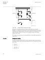 382
382
-
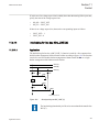 383
383
-
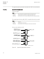 384
384
-
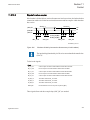 385
385
-
 386
386
-
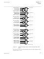 387
387
-
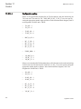 388
388
-
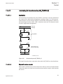 389
389
-
 390
390
-
 391
391
-
 392
392
-
 393
393
-
 394
394
-
 395
395
-
 396
396
-
 397
397
-
 398
398
-
 399
399
-
 400
400
-
 401
401
-
 402
402
-
 403
403
-
 404
404
-
 405
405
-
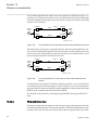 406
406
-
 407
407
-
 408
408
-
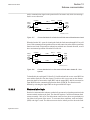 409
409
-
 410
410
-
 411
411
-
 412
412
-
 413
413
-
 414
414
-
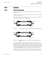 415
415
-
 416
416
-
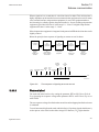 417
417
-
 418
418
-
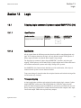 419
419
-
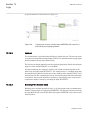 420
420
-
 421
421
-
 422
422
-
 423
423
-
 424
424
-
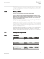 425
425
-
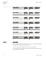 426
426
-
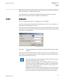 427
427
-
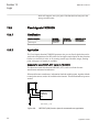 428
428
-
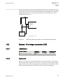 429
429
-
 430
430
-
 431
431
-
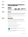 432
432
-
 433
433
-
 434
434
-
 435
435
-
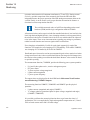 436
436
-
 437
437
-
 438
438
-
 439
439
-
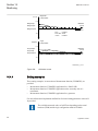 440
440
-
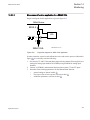 441
441
-
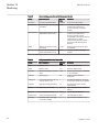 442
442
-
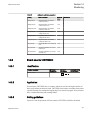 443
443
-
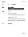 444
444
-
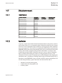 445
445
-
 446
446
-
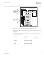 447
447
-
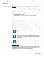 448
448
-
 449
449
-
 450
450
-
 451
451
-
 452
452
-
 453
453
-
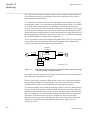 454
454
-
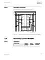 455
455
-
 456
456
-
 457
457
-
 458
458
-
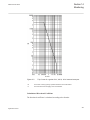 459
459
-
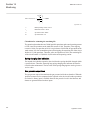 460
460
-
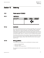 461
461
-
 462
462
-
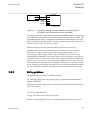 463
463
-
 464
464
-
 465
465
-
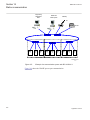 466
466
-
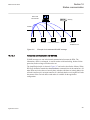 467
467
-
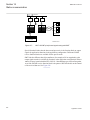 468
468
-
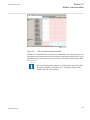 469
469
-
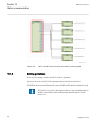 470
470
-
 471
471
-
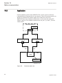 472
472
-
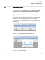 473
473
-
 474
474
-
 475
475
-
 476
476
-
 477
477
-
 478
478
-
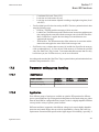 479
479
-
 480
480
-
 481
481
-
 482
482
-
 483
483
-
 484
484
-
 485
485
-
 486
486
-
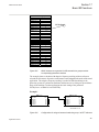 487
487
-
 488
488
-
 489
489
-
 490
490
-
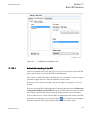 491
491
-
 492
492
-
 493
493
-
 494
494
-
 495
495
-
 496
496
-
 497
497
-
 498
498
-
 499
499
-
 500
500
-
 501
501
-
 502
502
-
 503
503
-
 504
504
-
 505
505
-
 506
506
-
 507
507
-
 508
508
-
 509
509
-
 510
510
-
 511
511
-
 512
512
-
 513
513
-
 514
514
-
 515
515
-
 516
516


in altre lingue
- English: ABB REL650 series
Documenti correlati
-
ABB RED650 Applications Manual
-
-
-
ABB 615 Series ANSI 5.0 FP1, Protection Relay Istruzioni per l'uso
-
ABB Relion REC615 Istruzioni per l'uso
-
-
-
Altri documenti
-
IFM DF2208 Istruzioni per l'uso
-
General Monitors TA402A Single Channel Trip Amplifier Manuale del proprietario
-
Eaton JDB Installation Instructions Manual
-
 Contrel ELR-4C Manuale utente
-
Eurotherm 414/415 Guida utente
-
IK Multimedia irig mic cast Manuale utente
-
WAGO Fieldbus Coupler Modbus TCP M12 Manuale utente
-
EcoFlow Smart Home Panel Combo(13 relay modules) Manuale utente
-
SEA SWING 2 MG Manuale del proprietario
-
Festo 8061196 Operating Instructions Manual
