
Integrated Control Solutions & Energy Savings
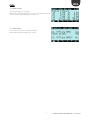
Technical lea et
Foglio istruzioni
supernode
controllo elettronico per umidi cazione
electronic controller for humidi cation

Simboli:
Attenzione: il simbolo nel coperchio plastico del controllo indica di riferirsi al presente foglio
istruzione durante l’installazione elettrica.
Symbol:
Warning: the symbol in the plastic cover of the control, means to refertto this techinical lea et,
during the electrical installation.

3
ENG
+050003325 Supernode for humidifi cation - 1.0 - 20.06.2014
1. INTRODUCTION
The gateway can connect up to a maximum of 20 devices (humiSteam Y-X-W, heaterSteam, gaSteam), allowing up to 150
variables (50 analogue, 50 integer, 50 digital) for each connected device to be managed by the external supervisor.
Seven pre-set templates allow the variables exchanged between the humidi er and the gateway to be addressed
automatically, depending on the device selected during programming: simply specify the type of device and the number
of devices connected. The built-in pGD on the Supernode or an external pGD1 terminal can be used for programming.
Supernode part number:
Description Carel P/N
Supernode for humidi cation + FLSTDmUGWS SNU0000EM0
On the external supervisor side, the protocol can be selected by choosing the corresponding optional serial card. The
possible options are:
item P/N description
1 Modbus®/CAREL RS485 PCOS0004850 Opto-isolated RS485 serial
2 LON PCO10000F0 LON FTT10 serial
3 BACnet™ Ethernet™ PCO1000WB0 Ethernet™ 8 MB serial
4 BACnet™ RS485 PCO1000BA0 BACnet™ MS/TP 485 serial
5 KONNEX PCOS00KXB0 KONNEX BMS port serial
tab. 1a
The module is DIN rail mounted, with 24 Vac power supply (+10%, -15%).
Supernode for humidi cation allows the possibility to select UR, UEX, UEW, UEY and UG humidi ers, including a combination
of di erent models.
For the address settings of the variables on the supervisor side, refer to the dynamic table, requesting from Carel the
“FLSTDmUGWS_Supervisory_List_dinamic_table_supernode_for_humidi cation” Excel le.
The application on Supernode also features the following options:
• Edit the humidi er model, if necessary add/re-address the pre-set variables
• Manage a generic device using the “Universal” model, which can be freely edited according to customer requirements

4
ENG
+050003325 Supernode for humidifi cation - 1.0 - 20.06.2014
2. INSTALLATION
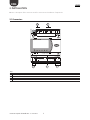
Below is a description of the connectors used for connection and installation of Supernode:
2.1 Connectors
1 5 2
3 4
J7
J10J9J8J5
J1
G
G0
+5Vref
+VDC
ID1
GND
J3
C1
NC1
NO1
J2
SYNC
B1
B2
B3
B4
B5
B6
GND
serial card 2
serial card 1
J4
J6
TLAN
GND
C2
NO2
GND
Y2
Y1
C622P028/R2
GNX
ISOLATED
Tx/Rx
PWM 0/10V
GNDTx/Rx
24 V (+10/-15%); 50/60 Hz
48 V (36Vmin…72 Vmax)
input voltage: max. power:
8 VA / 6 W
Key
1 power connector (G+,G0) 24 Vac or 36 V min...72 V max
2 SPDT relay digital output
3 pLAN network connector
4 optically-isolated “Field-Bus” serial connector
5 connector for BMS serial cards

5
ENG
+050003325 Supernode for humidifi cation - 1.0 - 20.06.2014
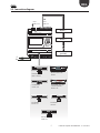
2.2 Connection diagram
serial card 1
serial card 2
status RS485
GNX RS485+ –
P1 P2 P3
BACnet
™
MS/TP
G0
G
RS485
CAREL master
GND
RS485
CAREL slave
PCOS004850:
RS485 serial card
PCO100MDM0:
modem card
PCO1000BA0:
BACnet™ MSTP RS485
interface
PCO1000WB0: pCO Web
- Ethernet™/BACnet™
interface card
PCO10000F0:
LON cards
PCO100CLP0:
TREND card
PCOS00KXB0:
Konnex card
device 1
device 2
device n
(n<=20)

6
ENG
+050003325 Supernode for humidifi cation - 1.0 - 20.06.2014
3. PROGRAMMING THE DEVICE
1. Set the number of devices connected to the gateway:
values available: from 1 to 20 devices.
Menu path: Service Service Settings Device settings
2. Set the address and type of device :
Models available: heaterSteam, humiSteam X-plus, humiSteam basic,
gaSteam, generic device
Menu path: Service Service Settings Device settings
The address setting and type of model must be selected for each
device connected to the gateway
3. Set the BMS1 and BMS2 serial port for reading by external
supervisor:
Address, protocol and baud rate setting.
Menu path: Service BMS Settings
4. Set the Carel master protocol for communication between
Supernode and devices:
Supernode communication protocol setting with devices: baud rate
(Retry n. and ORT can be left as default)
Note: the baud rate to be set always corresponds to the slowest
device connected (for heaterSteam the baud rate is 9600).
Menu path: Manufacturer Factory Settings

7
ENG
+050003325 Supernode for humidifi cation - 1.0 - 20.06.2014
5. Edit the model:
The selected model can be edited
Menu path: Manufacturer Devices con g 1-10 or Manufacturer
Devices con g 11-20 (depending on the device)
6. Alarm settings:
Enable alarms in the event of supervisor o ine
Menu path: Manufacturer Factory Settings

8
ENG
+050003325 Supernode for humidifi cation - 1.0 - 20.06.2014
Note:

CAREL INDUSTRIES HQs
Via dell’Industria, 11 - 35020 Brugine - Padova (Italy)
Tel. (+39) 049.9716611 - Fax (+39) 049.9716600
e-mail: [email protected] - www.carel.com
Agenzia / Agency:
+050003325 Supernode for humidifi cation - 1.0 - 20.06.2014
-
 1
1
-
 2
2
-
 3
3
-
 4
4
-
 5
5
-
 6
6
-
 7
7
-
 8
8
-
 9
9


in altre lingue
- English: Carel supernode
Documenti correlati
-
Carel UE008 Manuale utente
-
-
Carel humiSteam Basic UE018 Manuale utente
-
-
-
-
Carel heaterSteam Manuale utente
-
-
-