
MI950
LGA775 Core 2 Duo
Intel
®
Q45 Chipset
Mini-ITX Motherboard
USER’S MANUAL
Version 1.0

Acknowledgments
Award is a registered trademark of Award Software International,
Inc.
PS/2 is a trademark of International Business Machines
Corporation.
Intel is a trademark or registered trademark of Intel Corporation.
Microsoft Windows is a registered trademark of Microsoft
Corporation.
Winbond is a registered trademark of Winbond Electronics
Corporation.
All other product names or trademarks are properties of their
respective owners.

MI950 User’s Manual iii
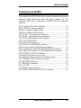
Table of Contents
Introduction ....................................................... 1
Checklist .............................................................................. 1
Product Description ............................................................. 2
Specifications ...................................................................... 3
Board Dimensions ............................................................... 4
Installations ....................................................... 5
Installing the CPU ............................................................... 6
ATX Power Installation ...................................................... 6
Installing the Memory ......................................................... 7
Setting the Jumpers ............................................................. 8
Connectors on MI950 ........................................................ 11
BIOS Setup ....................................................... 19
Drivers Installation ...................................... 41
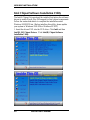
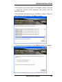
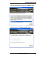
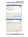
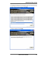
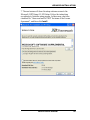
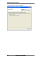
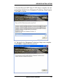
Intel Chipset Software Installation Utility......................... 42
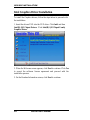
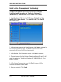
Intel Graphics Driver Installation ...................................... 44
Realtek HD Codec Audio Driver Installation ................... 46
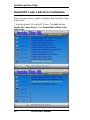
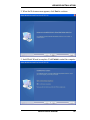
LAN Drivers Installation ................................................... 48
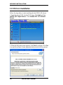
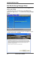
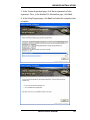
Intel Matrix Storage Manager Driver ................................ 50
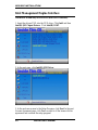
Intel Management Engine Interface .................................. 52
Intel Active Management Technology .............................. 54
Appendix ........................................................... 58
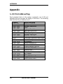
A. I/O Port Address Map ................................................... 58
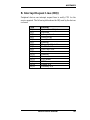
B. Interrupt Request Lines (IRQ) ...................................... 59
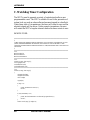
C. Watchdog Timer Configuration .................................... 60

iv
MI950 User’s Manual
This page is intentionally left blank.

INTRODUCTION
MI950 User’s Manual 1
Introduction
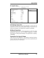
Checklist
Your MI950 Core 2 Duo motherboard package should include the items
listed below:
The MI950 motherboard
This User’s manual
1 x I/O shield
1 x serial port cable
2 x SATA cable
1 CD containing the following:
Chipset Drivers
Flash Memory Utility

INSTALLATIONS
2
MI950 User’s Manual
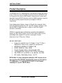
Product Description
The MI950 Mini-ITX motherboard is designed for either the Intel
Core2 Duo or Core2 Quad processors of up to 1333MHz FSB.
It is based on the Intel’s Q45 Express chipset and it comes with
two dual-channel DDR3 memory slots and 8GB memory capacity
for faster system responsiveness and support of 64-bit
computing.
Dual independent display comes to life with the onboard Intel
Q45 integrated graphics for CRT and DVI display interface. LAN
functionality is supported with a single or dual two Gigabit
Ethernet controllers.
MI950 is supports high-end features including high definition
audio, ten fast USB 2.0 ports, four SATAII and an eSATA port,
watchdog timer, digital I/O and four serial ports. Board
dimensions are 170mm by 170mm.
MI950 FEATURES
Supports Intel® Core™2 Quad / Core™2 Duo /
Pentium® Dual Core/ Celeron® processors
800MHz/1066MHz/1333MHz FSB
DDR3 DIMM x2, Max. 8GB
Single Gigabit LAN or dual Gigabit LAN
Integrated Q45 VGA for CRT & DVI interface
10x USB 2.0, 4x SATA II, 1x eSATA, 4x COM
HD audio, Watchdog timer, 1x PCI
REMARKS: For more information about the iAMT function (if you
have purchased the MI950AF board model), please go to the drivers
CD subdirectory - D:\ Intel\Q45\iAMT\iAMT5.0 User Manual\
(assuming D:\ is your CDROM drive).

INTRODUCTION
MI950 User’s Manual 3
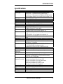
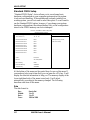
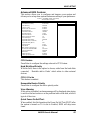
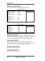
Specifications
Form Factor Mini-ITX
CPU Type Intel® Core™2 Extreme processor QX9000 series
Intel® Core™2 Quad processor Q9000 series,
Intel® Core™2 Duo processor E8000 and E7000 series
Intel® Pentium® Dual Core, Intel® Celeron® Dual Core
CPU Speed Up to 3.0 GHz
CPU FSB 800/1066/1333MHz FSB
L2 Cache Up to 6MB
Green /APM APM1.2
CPU Socket LGA775
Chipset Intel Eaglelake:Q45 + ICH10DO Chipset
BIOS Award BIOS, support ACPI Function
Memory DDRIII 800/1066MHz
- DIMM x 2 (w/o ECC), Max. 8GB
VGA - Intel Q45 GMCH integrated graphics device (GMA4500)
- Supports Direct X10 (Vista) & OpenGL 2.1
LAN 1. ICH10DO Gigabit MAC + Intel Gigabit PHY: Intel 82567
x1
2. Intel 82574L PCI-e Gigabit LAN controller x1
USB ICH10DO built-in USB 2.0 host controller, supports 10
ports
Serial ATA ICH10DO built-in SATA controller, 4x ports + 1x eSATA
Parallel IDE N/A
Audio ICH10DO built-in High Definition Audio controller:
ALC888 w/ 7.1 channels
LPC I/O Winbond W83627DHG: COM1 (RS232), COM2
(RS232/422/485), Hardware monitor
Fintek 81216 :COM3 (RS232)+ COM 4 (RS232)
Digital IO 4 in & 4 out
TPM1.2 N/A
Keyboard/Mouse
Connector
Via pin-header (For testing purpose only)
Expansion Slots PCI x1
Edge Connector:
COM1, DVI+VGA, GbE RJ-45 + dual USB stack
connector x2, Dual USB + e SATA stack connector,
RCA Jack 3x1 for HD Audio
On Board
Header/Connector
SATA x4 for 4 ports SATAI/SATAII,
2x4 pins pin-header x2 for 4 ports USB
2x5 pins pin-header x1 for front panel audio
2x5 pins pin-header x1 for COM2
2x10 pins pin-header for COM3, COM4
2x5 pins pin-header x1 for Digital IO
Watchdog Timer Yes (256 segments, 0, 1, 2…255 sec/min)
System Voltage +5V, +3.3V, +12V, -12V, 5VSB (2A)
Other LAN Wakeup, RAID
RoHS Yes
Board Size 170mm x 170mm

INSTALLATIONS
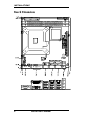
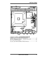
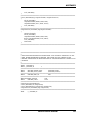
Board Dimensions
4
MI950 User’s Manual

INSTALLATIONS
MI950 User’s Manual 5
Installations
This section provides information on how to use the jumpers and
connectors on the MI950 in order to set up a workable system. The
topics covered are:
Installing the CPU ................................................................................. 6
ATX Power Installation ......................................................................... 6
Installing the Memory ........................................................................... 7
Setting the Jumpers ................................................................................ 8
Connectors on MI950 .......................................................................... 11

INSTALLATIONS
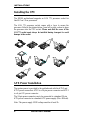
Installing the CPU
The MI950 motherboard supports an LGA 775 processor socket for
Intel® Core 2 Duo processors.
The LGA 775 processor socket comes with a lever to secure the
processor. Refer to the pictures below, from left to right, on how to place
the processor into the CPU socket. Please note that the cover of the
LGA775 socket must always be installed during transport to avoid
damage to the socket.
ATX Power Installation
The system power is provided to the motherboard with the ATX2 and
ATX1 power connectors. ATX2 is a 24-pin power connector and ATX1
is a 4-pin 12V power connector.
The 24-pin power connector can to be connected to a standard 20-pin
ATX power connector in a standard ATX power supply (Min. 400watt).
Note: The power supply 5VSB voltage must be at least 2A.
6
MI950 User’s Manual

INSTALLATIONS
MI950 User’s Manual 7
Installing the Memory
The MI950 motherboard supports two DDR3 memory sockets for a
maximum total memory of 8GB. It supports DDR3 800/1066MHz.
Basically, the system memory interface has the following features:
Supports two 64-bit wide DDR data channels
Available bandwidth up to 6.4GB/s (DDR3 1066) for two-channel
mode.
Supports 512Mb, 1Gb, 2Gb DDR3 technologies.
Supports only x8, x16, DDR3 devices with four banks
Supports only unbuffered DIMMs
Supports opportunistic refresh
Up to 32 simultaneously open pages (four per row, four rows
maximum)

INSTALLATIONS
8
MI950 User’s Manual
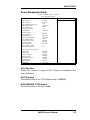
Setting the Jumpers
Jumpers are used on the motherboard are used to select various settings
and features according to your needs and applications. Contact your
supplier if you have doubts about the best configuration for your needs.
The following lists the connectors and their respective functions.
Jumper Locations on MI950/MI950F/MI950AF ................................... 9
JP4: ME (Management Engine) – Disabled / pin closed ..................... 10
JP5: Clear CMOS Contents ................................................................. 10
JP1, JP2, JP3: RS232/422/485 (COM2) Selection .............................. 10

INSTALLATIONS
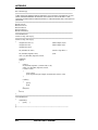
Jumper Locations on MI950/MI950F/MI950AF
Jumper Locations on MI950/MI950F/MI950AF .................................. 9
JP4: ME (Management Engine) – Disabled / pin closed ..................... 10
JP5: Clear CMOS Contents ................................................................. 10
JP1, JP2, JP3: RS232/422/485 (COM2) Selection .............................. 10
MI950 User’s Manual 9

INSTALLATIONS
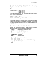
JP4: ME (Management Engine) – Disabled / pin closed
The factory default setting of the 2-pin JP4 jumper is closed. This means
the management engine function is disabled.
JP5: Clear CMOS Contents
Use JP8, a 3-pin header, to clear the CMOS contents.
Note that the ATX-power connector should be disconnected from the
motherboard before clearing CMOS.
JP5 Setting Function
Pin 1-2
Short/Closed
Normal
Pin 2-3
Short/Closed
Clear CMOS
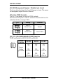
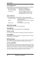
JP1, JP2, JP3: RS232/422/485 (COM2) Selection
COM2 is selectable for RS232, RS-422 and RS-485.
COM2
Function
RS-232 RS-422 RS-485
Jumper
Setting
(pin closed)
JP1:
1-2
JP2:
3-5 & 4-6
JP3:
3-5 & 4-6
JP1:
3-4
JP2:
1-3 & 2-4
JP3:
1-3 & 2-4
JP1:
5-6
JP2:
1-3 & 2-4
JP3:
1-3 & 2-4
10
MI950 User’s Manual

INSTALLATIONS
MI950 User’s Manual 11
Connectors on MI950
The connectors on MI950 allows you to connect external devices such as
keyboard, floppy disk drives, hard disk drives, printers, etc. The
following table lists the connectors on MI950 and their respective
functions.
ATX2: 24-pin ATX Power Connector ................................................ 13
ATX1: ATX 12V Power Connector .................................................... 13
DDRIII1: Channel A DDR3 Socket .................................................... 13
DDRIII2: Channel B DDR3 Socket .................................................... 13
CPU_FAN1: CPU Fan Power Connector ........................................... 13
SYS_FAN1: system Fan1 Power Connector ...................................... 13
SYS_FAN2: System Fan2 Power Connector ...................................... 14
CN1: Serial Ports(COM1) ................................................................... 14
CN2: DVI+CRT Connector ................................................................. 15
CN3: ESATA & USB8/USB9 Connector ........................................... 15
CN4: Line-in, Line-out & Microphone Connector .............................. 15
CN5: Gigabit LAN (Intel 574L) RJ-45 &USB 6/7 Connector ........... 15
CN6: Gigabit LAN (Intel 567LM) RJ-45&USB 4/5 Connector ......... 15
SATA1~SATA4: SATAII Connectors ................................................ 15
J1: Digital I/O Connector (4 in, 4 out)................................................. 15
J3: Keyboard & Mouse Connector (Testing use only) ........................ 16
J5: SPI Debug Tools Port (Factory use only) ...................................... 16
J6: USB2/USB3 Connector ................................................................. 16
J7: USB0/USB1 Connector ................................................................. 16
J8: Power LED .................................................................................... 16
J9: System Function Connector ........................................................... 16
J10: COM3, COM4 Serial Port (DF11 Connector) ............................. 17

INSTALLATIONS
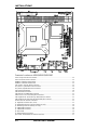
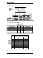
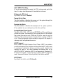
Connector Locations on MI950/MI950F/MI950RF
ATX2: 24-pin ATX Power Connector ................................................................................................... 13
ATX1: ATX 12V Power Connector ....................................................................................................... 13
DDRIII1: Channel A DDR3 Socket ....................................................................................................... 13
DDRIII2: Channel B DDR3 Socket ....................................................................................................... 13
CPU_FAN1: CPU Fan Power Connector .............................................................................................. 13
SYS_FAN1: system Fan1 Power Connector ......................................................................................... 13
SYS_FAN2: System Fan2 Power Connector ......................................................................................... 14
CN1: Serial Ports(COM1) ...................................................................................................................... 14
CN2: DVI+CRT Connector .................................................................................................................... 15
CN3: ESATA & USB8/USB9 Connector .............................................................................................. 15
CN4: Line-in, Line-out & Microphone Connector ................................................................................ 15
CN5: Gigabit LAN (Intel 574L) RJ-45 &USB 6/7 Connector ............................................................. 15
CN6: Gigabit LAN (Intel 567LM) RJ-45&USB 4/5 Connector ............................................................ 15
SATA1~SATA4: SATAII Connectors ................................................................................................... 15
J1: Digital I/O Connector (4 in, 4 out) ................................................................................................... 15
J3: Keyboard & Mouse Connector (Testing use only) ........................................................................... 16
J5: SPI Debug Tools Port (Factory use only) ......................................................................................... 16
J6: USB2/USB3 Connector .................................................................................................................... 16
J7: USB0/USB1 Connector .................................................................................................................... 16
J8: Power LED ........................................................................................................................................ 16
J9: System Function Connector .............................................................................................................. 16
J10: COM3, COM4 Serial Port (DF11 Connecto r) ................................................................................ 17
12
MI950 User’s Manual

INSTALLATIONS
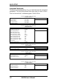
ATX2: 24-pin ATX Power Connector
Signal Name Pin # Pin # Signal Name
3.3V 13 1 3.3V
-12V 14 2 3.3V
Ground 15 3 Ground
PS-ON 16 4 +5V
Ground 17 5 Ground
Ground 18 6 +5V
Ground 19 7 Ground
-5V 20 8 Power good
+5V 21 9 5VSB
+5V 22 10 +12V
+5V 23 11 +12V
Ground 24 12 +3.3V
ATX1: ATX 12V Power Connector
This connector supplies the CPU operating voltage.
Pin # Signal Name
1 Ground
2 Ground
3 +12V
4 +12V
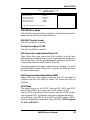
DDRIII1: Channel A DDR3 Socket
DDRIII2: Channel B DDR3 Socket
CPU_FAN1: CPU Fan Power Connector
Pin # Signal Name
1 Ground
2 +12V
3 Rotation detection
4 Control
SYS_FAN1: system Fan1 Power Connector
Pin # Signal Name
1 Ground
2 +12V
3 Rotation detection
MI950 User’s Manual 13

INSTALLATIONS
SYS_FAN2: System Fan2 Power Connector
14
MI950 User’s Manual
Pin # Signal Name
1 Ground
2 +12V
3 Rotation detection
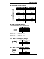
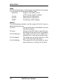
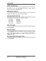
CN1: Serial Ports(COM1)
CN1 (COM1) is a DB-9 connector,
Signal Name Pin # Pin # Signal Name
DCD, Data carrier detect 1 6 DSR, Data set ready
RXD, Receive data 2 7 RTS, Request to send
TXD, Transmit data 3 8 CTS, Clear to send
DTR, Data terminal ready 4 9 RI, Ring indicator
GND, ground 5 10 Not Used
J2: COM2 is jumper selectable for RS-232, RS-422 and RS-485.
Pin # Signal Name
RS-232 R2-422 RS-485
1 DCD TX- DATA-
2 RX TX+ DATA+
3 TX RX+ NC
4 DTR RX- NC
5 Ground Ground Ground
6 DSR NC NC
7 RTS NC NC
8 CTS NC NC
9 RI NC NC
10 NC NC NC

INSTALLATIONS
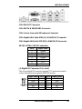
CN2: DVI+CRT Connector
CN3: ESATA & USB8/USB9 Connector
CN4: Line-in, Line-out & Microphone Connector
CN5: Gigabit LAN (Intel 574L) RJ-45 &USB 6/7 Connector
CN6: Gigabit LAN (Intel 567LM) RJ-45&USB 4/5 Connector
SATA1~SATA4: SATAII Connectors
Pin # Signal Name
1 Ground
2 TX+
3 TX-
4 Ground
5 RX-
6 RX+
7 Ground
J1: Digital I/O Connector (4 in, 4 out)
This 10-pin digital I/O connector supports TTL levels and is used to
control external devices requiring ON/OFF circuitry.
Signal Name Pin # Pin # Signal Name
Ground 1 2 +5V
Out3 3 4 Out1
Out2 5 6 Out0
IN3 7 8 IN1
IN2 9 10 IN0
MI950 User’s Manual 15

INSTALLATIONS
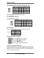
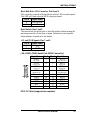
J3: Keyboard & Mouse Connector (Testing use only)
Signal Name Pin Pin Signal Name
Vcc 1 2 VCC
MDA 3 4 KBDA
MCL 5 6 KBCL
Ground 7 8 Ground
J5: SPI Debug Tools Port (Factory use only)
J6: USB2/USB3 Connector
J7: USB0/USB1 Connector
Signal Name Pin Pin Signal Name
Vcc 1 2 Ground
D0- 3 4 D1+
D0+ 5 6 D1-
Ground 7 8 Vcc
J8: Power LED
The power LED indicates the status of the main power switch.
Pin # Signal Name
1 Power LED
2 No connect
3 Ground
J9: System Function Connector
ATX Power ON Switch: Pins 1 and 2
This 2-pin connector is an “ATX Power Supply On/Off Switch” on the
system that connects to the power switch on the case. When pressed, the
power switch will force the system to power on. When pressed again, it
will force the system to power off.
16
MI950 User’s Manual
La pagina si sta caricando...
La pagina si sta caricando...
La pagina si sta caricando...
La pagina si sta caricando...
La pagina si sta caricando...
La pagina si sta caricando...
La pagina si sta caricando...
La pagina si sta caricando...
La pagina si sta caricando...
La pagina si sta caricando...
La pagina si sta caricando...
La pagina si sta caricando...
La pagina si sta caricando...
La pagina si sta caricando...
La pagina si sta caricando...
La pagina si sta caricando...
La pagina si sta caricando...
La pagina si sta caricando...
La pagina si sta caricando...
La pagina si sta caricando...
La pagina si sta caricando...
La pagina si sta caricando...
La pagina si sta caricando...
La pagina si sta caricando...
La pagina si sta caricando...
La pagina si sta caricando...
La pagina si sta caricando...
La pagina si sta caricando...
La pagina si sta caricando...
La pagina si sta caricando...
La pagina si sta caricando...
La pagina si sta caricando...
La pagina si sta caricando...
La pagina si sta caricando...
La pagina si sta caricando...
La pagina si sta caricando...
La pagina si sta caricando...
La pagina si sta caricando...
La pagina si sta caricando...
La pagina si sta caricando...
La pagina si sta caricando...
La pagina si sta caricando...
La pagina si sta caricando...
La pagina si sta caricando...
La pagina si sta caricando...
La pagina si sta caricando...
La pagina si sta caricando...
La pagina si sta caricando...
-
 1
1
-
 2
2
-
 3
3
-
 4
4
-
 5
5
-
 6
6
-
 7
7
-
 8
8
-
 9
9
-
 10
10
-
 11
11
-
 12
12
-
 13
13
-
 14
14
-
 15
15
-
 16
16
-
 17
17
-
 18
18
-
 19
19
-
 20
20
-
 21
21
-
 22
22
-
 23
23
-
 24
24
-
 25
25
-
 26
26
-
 27
27
-
 28
28
-
 29
29
-
 30
30
-
 31
31
-
 32
32
-
 33
33
-
 34
34
-
 35
35
-
 36
36
-
 37
37
-
 38
38
-
 39
39
-
 40
40
-
 41
41
-
 42
42
-
 43
43
-
 44
44
-
 45
45
-
 46
46
-
 47
47
-
 48
48
-
 49
49
-
 50
50
-
 51
51
-
 52
52
-
 53
53
-
 54
54
-
 55
55
-
 56
56
-
 57
57
-
 58
58
-
 59
59
-
 60
60
-
 61
61
-
 62
62
-
 63
63
-
 64
64
-
 65
65
-
 66
66
-
 67
67
-
 68
68


in altre lingue
- English: Award MI950 User manual
Altri documenti
-
DeLOCK 61386 Scheda dati
-
CyberResearch MXIH P4-34-X Manuale utente
-
MSI MS-S0571 Manuale utente
-
Tyan S5501 Informazioni importanti
-
-
-
-
Nvidia nForce 680I LT SLI Manuale utente
-
BCM MX67QM Manuale utente
-
ECS N2U400-A Manuale del proprietario