
This Installation Guide is comprised of pages [1/2] and [2/2]. This “Installation Guide”
explains the installation method of the camera using the ceiling mount cover (sold
separately). Please be sure to read the “Safety Precautions” section for correct use.
After reading this Installation Guide, keep it in a readily accessible location for future
reference. This camera is for indoor use only.
* Some cameras are not available in certain countries or regions.
WARNING
To reduce a risk of fire or electric shock, do not expose this product to rain
or moisture.
Caution
Request a professional installer for all installation work. Never try to install
the camera yourself. Doing so may result in unforeseen accidents such as
dropping the camera or electric shock.
Check Included Items
Camera Installation Guide (This document)
Power connector Warranty card
Symbols used in this Installation Guide
Parts indicated in the Installation Guide [2/2] with this icon are not included with the
camera, and should be provided by the user.
Accessories
The following accessories can be purchased separately as necessary. Some accessories are
not available in certain countries or regions. A ceiling mount cover or indoor dome housing is
necessary to install the camera on a ceiling.
Ceiling Mount Cover SS40-S-VB/SS40-B-VB
Dedicated accessory used to install the camera on a ceiling. The ceiling mount cover is
available in two colors: silver (SS40-S-VB) and black (SS40-B-VB).
Indoor Dome Housing DR41-C-VB/DR41-S-VB
Dedicated accessory used to embed the camera into the ceiling. The dome is available in
two colors: clear (DR41-C-VB) and smoked (DR41-S-VB).
Pendant Mounting Kit PC600-VB
Dedicated accessory used to install the camera to the end of pipe that extends from high
ceilings, such as in big-box stores.
Important
When this accessory is used, the camera may shake more than the vibrations in the ceiling depending
on how the pipe is mounted to the ceiling. If the camera angle is off, use pan and tilt to re-adjust the
angle.
AC Adapter PA-V18
Dedicated AC adapter for this camera.
Safety Precautions
Installation Precautions
Warning
Failure to follow the instructions may result in death or serious injury.
Do not install in the following places:
•
Places in direct sunlight, near heat-generating objects, or locations subject to high temperatures
• Places near fire sources or flammable solvents (alcohol, thinner, fuel, etc.)
• Humid or dusty places
• Places subject to oily smoke or steam
• Places subject to sea air
• Confined or enclosed places
Failure to do so may result in fire or electric shock.
Notes on Power Supply
• Only use the dedicated AC adapter (sold separately) ,when using AC adapter.
• Do not set any heavy objects on the power cable (or the LAN cable for a PoE power supply).
•
Do not pull, forcibly bend, scratch, or modify the power cable (or the LAN cable for a PoE power supply).
• Do not cover or wrap the AC adapter (sold separately) with cloth or blankets.
Failure to do so may result in fire or electric shock.
Caution
Failure to follow the instructions may result in injury.
For installation or inspection of this camera, consult the dealer where you purchased the product.
• This installation should be made by a qualified service person and should conform to all local codes.
• When installing, make sure the surface is capable of withstanding the total weight of the camera and
accessories, and sufficiently reinforce if necessary.
• Be sure to use installation screws designed for the type of surface the camera is to be installed.
• Periodically check the parts and screws for rust and loosening, in order to prevent injuries and
equipment damage due to falling items.
• Do not install in unstable places, places subject to significant vibration or impact, or places subject to
salt damage or corrosive gas.
• The camera cannot be installed on vertical surfaces such as walls.
• Be sure to attach the safety wire when installing the camera.
Failure to do so may result in the camera falling or other accidents.
• Do not touch the edges of metal parts with bare hands.
• Be careful not to get your fingers caught when installing.
Failure to do so may result in injuries.
Caution
Failure to follow the instructions may result in property damage.
• Do not hold the device by the camera head.
• Do not turn the camera rotator by hand.
• Never touch the camera head during initialization.
• Do not install on an unstable surface. Also, make sure the camera is installed ±5° or less horizontal.
• After turning off the power, do not turn the power on again for at least five seconds.
• Take measures to remove static electricity before performing any procedures.
• If there is condensation, please wait to power on, until the condensation dissipates.
• The network camera is only intended for a connection to an Ethernet or PoE network without routing to
the outside plant.
Failure to do so may result in malfunctions.
• Take care not to damage wiring or piping.
Failure to do so may result in damage to peripheral items.
Important
• We recommend the installation of a lightning arrester (a surge protection device) as a measure
against failures caused by lightning strikes. Please refer to our website for details.
• The camera can be installed in the upright position. Attach commercial anti-slip guards to the base
of the camera and set on a flat, stable surface without inclination, or fix the camera to a tripod, etc.
Be sure to use a tripod with mounting screws shorter than 5.5 mm (0.22 in.). Using a tripod with
mounting screws 5.5 mm (0.22 in.) or longer may damage the camera. Also, use a tripod with a base
diameter of 30 mm (1.18 in.) or more.
Precautions for Use
Warning
Failure to follow the instructions may result in death or serious injury.
• If you discover defective conditions such as smoke, strange sounds, heat or strange odors,
immediately stop using the camera and contact your nearest dealer.
Fire or electric shock may result from continued use of the product.
•
If thunder starts, stop installation or inspection etc. and do not touch the camera or continue connecting the cable.
• Do not disassemble or modify the camera.
• Do not damage the connecting cable.
• Do not spray the camera with water, or otherwise make it wet.
• Do not insert foreign objects such as water or metal into the camera.
• Do not use flammable sprays near the camera.
• Do not leave LAN cables, external power supply, or the power connector for the AC adapter (sold
separately) connected when the camera is not in use for long periods.
• Do not use flammable solvents such as alcohol, paint thinner or benzine when cleaning the camera.
Failure to do so may result in fire or electric shock.
• This camera should not be used with medical devices or other life-support systems.
• Depending on the computer and network environment, high-precision video transmission cannot be
guaranteed due to video lag or loss.
Canon will assume no liability for any accident or damage resulting from use of the camera
under the conditions above.
Only for European Union and EEA (Norway, Iceland and Liechtenstein)
These symbols indicate that this product is not to be disposed of with your household waste,
according to the WEEE Directive (2012/19/EU), the Battery Directive
(2006/66/EC) and/or national legislation implementing those Directives.
If a chemical symbol is printed beneath the symbol shown above, in
accordance with the Battery Directive, this indicates that a heavy metal
(Hg = Mercury, Cd = Cadmium, Pb = Lead) is present in this battery
or accumulator at a concentration above an applicable threshold
specified in the Battery Directive.
This product should be handed over to a designated collection point, e.g., on an authorized
one-for-one basis when you buy a new similar product or to an authorized collection site for
recycling waste electrical and electronic equipment (EEE) and batteries and accumulators.
Improper handling of this type of waste could have a possible impact on the environment
and human health due to potentially hazardous substances that are generally associated
with EEE. Your cooperation in the correct disposal of this product will contribute to the
effective usage of natural resources.
For more information about the recycling of this product, please contact your local city
office, waste authority, approved scheme or your household waste disposal service or visit
www.canon-europe.com/weee, or www.canon-europe.com/battery.
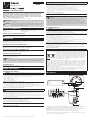
Part Names
7
9
10
1 2
3 4 5 6
11
8
12
Serial_ _ _ _ _ _ _ _ _ _ _ _ _ _ _ _ _
MAC_ _ _ _ _ _ _ _ _ _ _ _ _ _ _ _ _ _
1. Audio input terminal (common LINE IN and MIC IN) / 2. Audio output terminal (LINE OUT) /
3. 100Base-TX LAN connector / 4. Power connection terminal / 5. Reset Switch*
1
/
6. External Device I/O Terminals / 7. Fixing screw hole for tripod / 8. Safety wire attachment /
9. LED (Blue)*
2
/ 10. Memory card cover / 11. Lens / 12. Camera head
*
1
Please refer to the “Operation Guide” for the method to reset the camera.
*
2
On: when powered on, during reboot, during normal use / Off: when [Turn Off] is selected
(please refer to the “Operation Guide”)
The contents of this guide are subject to change without any prior notice.
Network Camera
/
ENGLISH
BIE-7200-000
Installation Guide
1
2

External Device Output Terminals (OUT1, OUT2)
External device output terminals consist of two sets (OUT1, OUT2) of two terminals. The sets
have no polarity. Controls from the viewer can be used to open and close the circuit between
the terminals. Using optical couplers, the output terminals are isolated from the camera’s
internal circuit.
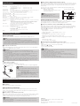
Internal Connection Diagram
Internal controller
External device
Input terminal
IN1, IN2
Output terminal
OUT1, OUT2
+3.3 V
0.1 µF
10 kΩ 10 kΩ
1 kΩ
External device
The load connected to the output terminals should be within the following rating range.
Rating between output terminals:
Maximum voltage 50 V DC
Continuous load current at or below 100 mA
On resistance: Max. 30 Ω
Note
Adaptive wiring for external device cables
Solid conductor AWG: No. 28 – 22
Cable strip should be approx. 8 – 9 mm (0.31 – 0.35
in.)
Audio Input/Output Terminals
Each audio input/output terminal has one input system and one output system.
Connecting the camera to an audio input/output device such as a microphone or a speaker
with an amplifier allows you to send/receive audio through the viewer.
Audio Input Terminal Common LINE IN/MIC IN (monaural input)
Although the camera has a single audio input system, it supports two types of microphone
input: LINE IN and MIC IN. Before using the audio input, change [Audio Input Mode] on the
Setting Page (please refer to the “Operation Guide”). LINE IN is selected by default.
Input terminal:
3.5 mm ( 0.14 in.) mini jack (monaural)
• Dynamic MIC IN
Input impedence: 1.5 kΩ ±5%
* Supported microphones: Output impedence: 400 Ω – 600 Ω
• Condenser MIC IN
Input impedence (microphone bias resistance): 2.2 kΩ ±5%
Microphone power supply: plug-in power (voltage: 1.8 V)
* Supported microphones: Condenser microphones with plug-in power support
• LINE IN
Input level: up to 1 Vp-p
* Use a microphone with an amplifier.
Audio Output Terminal LINE OUT (monaural output)
Connect the camera to a speaker with an amplifier. Audio can be sent to the speaker from
Viewer.
Output terminal:
3.5 mm ( 0.14 in.) mini jack (monaural)
Output level: up to 1 Vp-p
* Use a speaker with an amplifier.
Important
• Using incorrect settings for [Audio Input Mode] may damage the camera and/or microphone. Be sure
to configure the settings correctly.
• Microphone characteristics may affect volume and sound quality.
• Images and audio do not always synchronize properly.
• Audio may be interrupted depending on PC characteristics and network environment.
• Video and audio can be streamed to up to 30 clients. However, audio may be interrupted when
streaming to many clients or using SSL.
• Audio may be interrupted when using antivirus software.
• Connecting and disconnecting the LAN cable interrupts the audio. Use the viewer to reconnect.
© CANON INC. 2017 Printed in Taiwan
Specifications
Please refer to the “Specifications” for specifications not listed below.
Lens 20x optical zoom (20x digital zoom) lens with auto focus
Viewing Angle For 16:9 aspect ratios
Horizontal: 60.4° (W) – 3.2° (T) Vertical: 35.1° (W) – 1.8° (T)
For 4:3 aspect ratios
Horizontal: 46.3° (W) – 2.4° (T) Vertical: 35.1° (W) – 1.8° (T)
Pan Angle Range 340° (±170°)
Tilt Angle Range 100° (ceiling-mounted position: -90° – +10°) When the horizontal direction of the camera is 0°
Network Terminal*
LAN x 1 (RJ45, 100Base-TX (auto/full-duplex/half-duplex))
* Use a category 5 or better LAN cable, 100 m (328 ft.) or less in length.
Audio Input Terminal 3.5 mm ( 0.14 in.) mini-jack connector (monaural)
(common for LINE IN & MIC IN)
Audio Output Terminal
3.5 mm ( 0.14 in.) mini-jack connector (monaural)
(LINE OUT)
External Device I/O Terminal
Input x 2, Output x 2
Memory Card SD Memory Card, SDHC Memory Card, SDXC Memory Card Compatible.
Operating Environment Temperature: AC, DC, PoE: -10°C – +50°C (+14°F – +122°F)
Humidity: 5% – 85% (without condensation)
Storage Environment
Temperature: -30°C – +60°C (-22°F – +140°F)
Humidity: 5% – 90% (without condensation)
Installation Ceiling mount
– Canon will not guarantee proper operation if the cameras are installed on surfaces
where the angle is more than ±5° from horizontal or on walls, because this will put a
heavy load onto sliding mechanical parts and may affect durability.
Power Supply
PoE: PoE power supply via LAN connector (IEEE802.3at Type1 compliant)
AC Adapter: PA-V18 (100 – 240 V AC) (sold separately)
External power source: 24 V AC/12 V DC
Power Consumption PoE: Max. approx. 9.2 W*
AC Adapter PA-V18: Max. approx. 9.9 W (100 V AC)
Max. approx. 9.4 W (240 V AC)
DC: Max. approx. 8.6 W
AC: Max. approx. 8.8 W
* Class 0 power sourcing equipment (requests 15.4 W)
Weight Approx. 1140 g (2.52 lb.)
Connecting the Camera
Power Connection
Please be sure to read the user manual for the dedicated power supply before use.
Note
• Power supply should conform to all local codes.
• The power supply should also comply with IEC/UL60950-1 (SELV/LPS) standards.
• The camera does not have a power switch. Connecting and disconnecting the LAN cable (PoE power
supply), AC adapter, or external power supply plug turns the power ON and OFF, respectively.
• When the camera needs to be rebooted, perform the reboot operation from the camera setting page
(please refer to the “Operation Guide”).
PoE (Power over Ethernet)
Power can be supplied to the camera by using a LAN cable to connect it to a PoE HUB that
conforms to the IEEE802.3at Type1 standard.
Important
• Check with your dealer for more information about PoE HUB and Midspan technology.
Midspan (a LAN cable power supply device) is a device that, like a PoE HUB, supplies power to the
camera via a LAN cable.
• Some PoE HUBs allow the limitation of power for each port, but applying limits may interfere with
performance. If using this type of PoE HUB, do not limit the operating power.
• Some PoE HUBs have limits for the total power consumption for the ports, which can interfere with
performance when multiple ports are in use. For more information, check the instruction guide for
your PoE HUB.
• The camera can also be connected to an AC adapter (sold separately) while receiving power from
a PoE HUB. In such cases, the PoE power supply is given priority, and the camera does not use the
power supply from the AC adapter (sold separately). When the PoE power supply is disconnected,
power is supplied automatically from the AC adapter (sold separately).
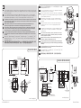
External Power Supply
12 V DC or 24 V AC input can be used.
Connect the included power connector as shown below.
Screwdriver
Tightening torque: 0.25 N·m
(max.)
Strip
Approx. 5 – 7 mm
(0.20 – 0.28 in.)
Power connector
(included)
12 V DC can be connected in a non-polar configuration.
Important
• The power supply should be within the following voltage
range.
• 24 V AC: Voltage fluctuation within ±10% of 24 V AC (50 Hz
or 60 Hz ±0.5 Hz or less)
Current supply capacity of at least 1.0 A per camera
• 12 V DC: Voltage fluctuation within ±10% of 12 V DC
Current supply capacity of at least 1.5 A per camera
• When using a 12 V DC battery power supply, be sure to
connect resistors of at least 0.5 – 1.0
Ω/20 W in series to the
power line.
• For an external power supply, use a double-insulated device.
Recommended Power Cables [Reference]
Cable (AWG)
24 22 20 18 16
12 V DC maximum cable length m (
ft.
)
5 (16.4) 9 (29.5) 14 (45.9) 23 (75.5) 32 (105.0)
24 V AC maximum cable length m (
ft.
)
11 (36.1) 18 (59.1) 29 ( 95.1) 46 (150.9) 64 (210.0)
Use UL cable (UL-1015 or equivalent) for 12 V DC or 24 V AC wiring.
AC Adapter
Use the dedicated AC adapter (sold separately).
External Device I/O Terminals
External device I/O terminals consist of two input and output systems each. Viewer can be
used to check external device input status and control ouput to an external device (please
refer to the “Operation Guide”).
External Device Input Terminals (IN1, IN2)
External device input terminals consist of two sets (IN1, IN2) of two terminals, with the negative
terminals connected to the camera interior GND. Connecting cables to the positive and
negative terminals and opening or closing the circuit notifies the Viewer.
Important
• When connecting sensors and switches, connect terminals that are electrically isolated from the
respective power and GND.
• Do not push the external device I/O terminal button with too much force. Doing so may cause the
button to remain pushed-in.
CANON INC.
30-2, Shimomaruko 3-chome, Ohta-ku, Tokyo 146-8501, Japan
CANON EUROPA N.V.
Bovenkerkerweg 59, 1185 XB Amstelveen, The Netherlands


2
FR
S’il est impossible de placer les câbles au-dessus d’un plafond en béton, par exemple, coupez la section
de découpe du boîtier de dôme à l’aide de pinces diagonales afin de créer une découpe qui permettra de
faire passer les câbles.
IT
Se non è possibile ammassare i cavi sopra un soffitto fatto di cemento e così via, o se i cavi non entrano
dentro il coperchio per installazione a soffitto, piegare la sezione ritagliata del coperchio per installazione a
soffitto utilizzando pinze diagonali e così via, per creare un ritaglio attraverso cui far passare i cavi
RU
Есликабелинельзяпроложитьнадбетоннымпотолкомилиесликабелинеумещаютсявнутрикрышкидля
потолочногомонтажа,кусачкамиотогнитеотрезнуючастькрышкидляпотолочногомонтажа,чтобысоздать
прорезьдляпрокладкикабелей.
TR
Kablolarbetondanyapılmışbirtavanınüzerindesaklanamıyorsa,kablolarıyönlendirebileceğinizbiroyuk
oluşturmakiçindiyagonalpensevb.kullanaraktavanamontekapağınkesmebölümünübükün.
PL
Jeśliniemożnaumieścićkablipowyżejsutuwykonanegozbetonuitp.lubjeślikableniemieszcząsię
wpokrywiemocowaniasutowego,należywygiąćwyciętączęśćwpokrywiemocowaniasutowegoza
pomocąszczypiecitp.,abyutworzyćotwór,przezktóryzostanąprzeprowadzonekable.
TH
KO
콘트리트 천장 등에서 케이블이 천장과 지붕 사이의 공간에 들어가지 않는 경우나, 케이블이 천장 장착용
커버에 들어가지 못하는 경우는 천장 장착용 커버의 노치 부분을 니퍼 등으로 접어서 케이블이 통하는
노치를 만들어 주십시오.
ZH
如果无法将连接线放入混凝土等材料的天花板上方,或者连接线不适合放入吊顶外罩内,请用
斜嘴钳或其他工具弯折吊顶外罩的挖除部分,创建一个可引导连接线通过的挖除口。
161 (6.34)
10°
90°
R55 (R2.17)
132 ( 5.20)
18
(0.71)
155 (6.10)
112.5 (4.43)
48
(1.89)
4-M3
47
(1.85)
47
(1.85)
15 (0.59)15 (0.59)
VB-H45/VB-M44
mm in pulg po
© CANON INC
2017
Printed in Taiwan
JA
EN
To use the Junction Box, be sure to use the ceiling plate included with
the Ceiling Mount Cover (sold separately).
DE
Wenn Sie die Anschlussdose verwenden, verwenden Sie unbedingt die
Deckenplatte, die im Lieferumfang der Abdeckung für Deckenhalterung
(separat erhältlich) enthalten ist.
ES
Para utilizar la caja de empalmes, asegúrese de utilizar la plancha
de techo incluida con la cubierta de montaje en techo (se vende por
separado).
FR
Pour utiliser le boîtier de jonction, assurez-vous d’utiliser la plaque
de fixation incluse avec le couvercle de support plafond (vendu
séparément).
IT
Per utilizzare la scatola di giunzione, assicurarsi di utilizzare la piastra
a soffitto inclusa con il coperchio per installazione a soffitto (venduto
separatamente).
RU
Чтобыиспользоватьклеммнуюкоробку,обязательноиспользуйте
потолочнуюпланку,входящуювкомплекткрышкидляпотолочного
монтажа(продаетсяотдельно).
TR
BağlantıKutusunukullanmakiçinTavanaMonteKapakla(ayrısatılır)
birliktetavanplakasınıkullandığınızdaneminolun.
PL
Wprzypadkuużywaniaskrzynkiprzyłączowejnależyzastosowaćpłytę
sutowądołączonądopokrywymocowaniasutowego(sprzedawanego
oddzielnie).
TH
KO
전공 박스를 이용할 경우는 옵션품인 천장 장착용 커버에 동곤된 장착용
플레이트를 사용해 주십시오 .
ZH
要使用接线盒,请确保使用吊顶外罩 ( 另购 ) 随附的吊顶板。
M
3
x
4
M
3
x
4
180 (7.09)
66
(2.60)
45
(1.77)
22 (0.87)
160 (6.30)
140 (5.51)
116 (4.57)
20
(0.79)
20
(0.79)
144 (5.67)
65
(2.56)
4- 3.4 ( 0.13)
4- 3.4 ( 0.13)
4- 4.5 ( 0.18)
83.5 (3-9/32)
85.7 (3-3/8)
85.7 (3-3/8)
83.5 (3-9/32)
46 (1-13/16)
46 (1-13/16)
14- 4.5 ( 0.18)
mm in pulg po
SS40-S-VB/SS40-B-VB
-
 1
1
-
 2
2
-
 3
3
-
 4
4


Canon VB-M44 Manuale utente
- Tipo
- Manuale utente
- Questo manuale è adatto anche per
in altre lingue
- English: Canon VB-M44 User manual
Documenti correlati
Altri documenti
-
Panasonic WZ-CW380 Istruzioni per l'uso
-
JVC VN-T216VPRU Manuale utente
-
Axis Q6034-E Guida d'installazione
-
Axis AXIS 215 PTZ Guida d'installazione
-
Axis P5532 Manuale utente
-
-
Axis Q6035 Guida d'installazione
-
NEC NP01SW1 Manuale del proprietario
-
Axis P5544 Manuale utente
-
Avigilon 8.0MP-HD-DOME-360 Guida d'installazione