ProLights DIGIDRIVERIP Manuale utente
- Categoria
- Proiettori
- Tipo
- Manuale utente
Questo manuale è adatto anche per

USER MANUAL
MANUALE UTENTE
EN - IT
DIGIDRIVERIP
DIGISTRIPIP50
DIGISTRIPIP100
MASTER DRIVER
PIXEL-MAP LED BAR

All rights reserved by Music & Lights S.r.l. No part of this instruction manual may be
reproduced in any form or by any means for any commercial use.
In order to improve the quality of products, Music&Lights S.r.l. reserves the right to modify the
characteristics stated in this instruction manual at any time and without prior notice.
All revisions and updates are available in the ‘manuals’ section on site www.musiclights.it
REV.02-12/19

1
DIGIDRIVERIP - DIGISTRIPIP50 - DIGISTRIPIP100
Packing content
• DIGIDRIVERIP / DIGISTRIPIP100
/ DIGISTRIPIP50
• User manual
TABLE OF CONTENTS
Safety
General instructions
Warnings and installation precautions
1 Description and Technical specifications
1. 1 DIGIDRIVERIP
1. 2 DIGISTRIPIP50
1. 3 DIGISTRIPIP100
1. 4 Operating elements and connections
2 Installation
2. 1 Mounting
2. 2 Maximum cable distance
3 Functions and settings
3. 1 Operation
3. 2 Basic setup
3. 3 Menu structure
3. 4 DMX control
4 Connection diagram
5 Maintenance
5. 1 Maintenance and cleaning the unit
5. 2 Fuse replacement
2
2
3
4
5
6
7
7
8
8
9
11
17
18
18

DIGIDRIVERIP - DIGISTRIPIP50 - DIGISTRIPIP100
2
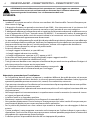
SAFETY
General instruction
• The products referred to in this manual conform to the European Community Directives and are
therefore marked with.
• The unit is supplied with hazardous network voltage (230V~). Leave servicing to skilled personnel only.
Never make any modifications on the unit not described in this instruction manual, otherwise you will
risk an electric shock.
• Connection of the power adapter must be made to a power supply system fitted with efficient earthing
(Class I appliance according to standard EN 60598-1). It is, moreover, recommended to protect the
supply lines of the units from indirect contact and/or shorting to earth by using appropriately sized
residual current devices.
• The connection to the main network of electric distribution must be carried out by a qualified electrical
installer. Check that the voltage correspond to those for which the unit is designed as given on the
electrical data label.
• This unit is not for home use, only professional applications.
• Never use the fixture under the following conditions:
- in places subject to vibrations or bumps;
- in places subject to excessive humidity;
- in places with a temperature of over 45 °C or -40°C.
• Make certain that no inflammable liquids, water or metal objects enter the fixture.
• Do not dismantle or modify the fixture.
• All work must always be carried out by qualified technical personnel. Contact the nearest sales point
for an inspection or contact the manufacturer directly.
• If the unit is to be put out of operation definitively, take it to a local recyclingplant for a disposal which
is not harmful to the environment.
Warnings and installation precautions
• If this device will be operated in any way different to the one described in this manual, it may suffer
damage and the guarantee becomes void. Furthermore, any other operation may lead to dangers like
short circuit, burns, electric shock, etc.
• Every person involved with installation and maintenance of this device have to be qualified and follow
the instructions of this manual.
• Before starting any maintenance work or cleaning the projector, cut off power from the main supply.
• Always additionally secure the projector with the safety rope. When carrying out any work, always
comply scrupulously with all the regulations (particularly regarding safety) currently in force in the
country in which the fixture’s being used.
• Install the fixture in a well ventilated place.
• Keep any inflammable material at a safe distance from the fixture.
• Never look directly at the light beam. Please note that fast changes in lighting, e. g. flashing light, may
trigger epileptic seizures in photosensitive persons or persons with epilepsy.
• When cleaning product, please do not use solvents such as acetone or alcohol, since they may damage
the of the unit outer finish and the printings on the panels.
• This product was designed and built strictly for the use indicated in this documentation. Any other use,
not expressly indicated here, could compromise the good condition/operation of the product and/or
be a source of danger.
• We decline any liability deriving from improper use of the product.
WARNING! Before carrying out any operations with the unit, carefully read this instruction
manual and keep it with cure for future reference. It contains important information about
the installation, usage and maintenance of the unit.

3
DIGIDRIVERIP - DIGISTRIPIP50 - DIGISTRIPIP100
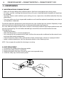
- 1 - INTRODUCTION
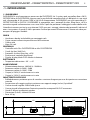
1.1 DIGIDRIVERIP
DIGIDRIVERIP is a driver which provides power and processing to the DIGISTRIPIP. It has 2 outputs and can
control up to 20 DIGISTRIPIP100s and 40 DIGISTRIPIP50s - each offering the control of up to 3.600 pixels in
a one rack unit, offering 20 DMX universes and 546 W of power in and out. DIGIDRIVERIP cannot control
DIGISTRIP, DIGITUBE and DIGITILE. DIGIDRIVERIP is compatible with Art-Net, Kling-Net and sACN protocols
and runs signal and power over a 4 pole XLR cable that allow wiring of units in a chain. The user interface
consists of a black OLED display for settings, protocol selection, network address and test patterns. IP 65
rating allows for the usage at outdoor events so humidity and rain are no longer a worry
BODY
• Hardware on-board: Included rack-mount hardware
• Body: sturdy die-cast aluminium body conceived for long-time durability
• Body colour: black
• Other: 2U rack
CONTROL
• Control units: 20 x DIGISTRIPIP100 or 40 x DIGISTRIPIP50
• Art-Net channels: 20x512ch
• Protocols: Art-Net, Kling-Net, sACN
• Pixel control: pixel2pixel control
• Display: black OLED high resolution display
ELECTRONICS
• Operating temperature: -20° ~ +45°
ELECTRICAL
• Power supply: 100-240 V – 50/60 Hz
• Power consumption (at 230 V): 546W
• Power consumption (at 120 V): 570W
• Output (at 230 V): 5 units on a single power line
• Output (at 120 V): 2 units on a single power line
PHYSICAL
• Cooling: natural cooling of the peculiar chassis and to absence of fans
• Sospension and fixing: any position with quick-lock omega brackets
• Signal connection: 2xRJ45 and 4p out
• Power connection: Seetronic powerCON waterproof IN/OUT connectors
• IP rating: 65 for outdoor installations
• Dimensions (WxHxD): 483x84x250 mm
• Weight: 4.5 kg
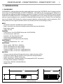
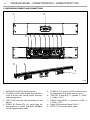
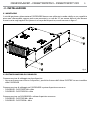
Fig.1Technical drawing
84
483 263

DIGIDRIVERIP - DIGISTRIPIP50 - DIGISTRIPIP100
4
500
33
114
100
121
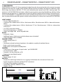
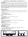
Fig.2Disegno tecnico
1.2 DIGISTRIPIP50
DIGISTRIPIP50 is a linear LED 10 mm pixel pitch video fixture for the rental market with an extensive range
of optical accessories for a wide variety of looks (black and white included, transparent on demand). Each
50 cm long strip features 50 RGB / FC LEDs with individual pixel control and a 100° viewing angle. The
mechanics of DIGISTRIPIP50 have been studied to grant greater mounting flexibility by adding sliding
hardware on the back for truss application and on the side for multiple vertical linking. The external con-
trol unit DIGIDRIVERIP is compatible with Art-Net and Kling-Net protocol and runs both signal and power
over a 4 pole cable that provides greater stability and connection in a daisy chain (up to 40 DIGISTRIPIP50).
LIGHT SOURCE
• Source: 50x0,25W RGB LEDs
• Luminous flux: without cover: 263 lm - black cover: 60 lm - flat white cover: 202 lm - dome white cover:
202lm
• Luminous flux: without cover: 4.320 nit - black cover: 727 nit - flat white cover: 1.233,6 nit - dome white
cover: 681,3
• Lux: 587 lx with clear coverlx
• Source life expectancy: > 50.000 h
• Other: view angle 100° - driver chip MBI 5043
OPTICS
• Pixel pitch: 10mm
• Additional optics: black cover and white dome cover (included)
• Other: flat white cover (included)
COLOUR SYSTEM
• Colour mixing: RGB / FC
• BODY
• Hardware on-board: on board mechanics for modular assembly of multiple fixtures
• Body: sturdy aluminum profile
• Body colour: white optic and body black
CONTROL
• Control units: 40 pcs power & signal under 1 pc DIGIDRIVERIP
• Art-Net channels: 150ch
• Protocols: Art-Net, Kling-Net, sACN
• Pixel control: pixel2pixel control
ELECTRICAL
• Power supply: DC 48 V
PHYSICAL
• Sospension and fixing: bracket for truss rigging and hardware for connection of more units
• Signal connection: Seetronic XLR 4p IN/OUT connectors
• IP rating: 65 for outdoor installations
• Dimensions (WxHxD): 500x33x114 mm
• Weight: 1,35 kg

5
DIGIDRIVERIP - DIGISTRIPIP50 - DIGISTRIPIP100
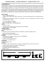
1000
88
100
128
34
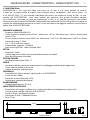
Fig.3Disegno tecnico
1.3 DIGISTRIPIP100
DIGISTRIPIP100 is a linear LED 10 mm pixel pitch video fixture for the rental market with an extensive
range of optical accessories for a wide variety of looks (black and white and transparent). Each 1 meter
long strip features 100 RGB / FC LEDs with individual pixel control and a 100° viewing angle. The mechan-
ics of DIGISTRIPIP100 have been studied to grant greater mounting flexibility by adding sliding hardware
on the back for truss application and on the side for multiple vertical linking. The external control unit
DIGIDRIVERIP is compatible with Art-Net and Kling-Net protocol and runs both signal and power over a 4
pole cable that provides greater stability and connection in a daisy chain (up to 20 DIGISTRIPIP100)
LIGHT SOURCE
• Source: 100x0,25W RGB LEDs
• Luminous flux: without cover: 620 lm - black cover: 101 lm - flat white cover: 382 lm - dome white cover:
411lm
• Luminous flux: without cover: 8’639,7 nit - black cover: 1’454,7 nit - flat white cover: 2’467,3 nit - dome
white milky cover: 1’362,6
• Lux: 1’174 lx with clear coverlx
• Source life expectancy: > 50.000 h
• Other: view angle 100° - driver chip MBI 5043
OPTICS
• Pixel pitch: 10mm
• Additional optics: black cover and white dome cover (included)
• Other: flat white cover (included)
COLOUR SYSTEM
• Colour mixing: RGB / FC
BODY
• Hardware on-board: on board mechanics for modular assembly of multiple fixtures
• Body: sturdy aluminum profile
• Body colour: white optic and body black
CONTROL
• Control units: 20 pcs power & signal under 1 pc DIGIDRIVERIP
• Art-Net channels: 300ch
• Protocols: Art-Net, Kling-Net, sACN
• Pixel control: pixel2pixel control
ELECTRICAL
• Power supply: DC 48 V
PHYSICAL
• Sospension and fixing: bracket for truss rigging and hardware for connection of more units
• Signal connection: Seetronic XLR 4p IN/OUT connectors
• IP rating: 65 for outdoor installations
• Dimensions (WxHxD): 1.000x36x128 mm
• Weight: 2,7 kg

DIGIDRIVERIP - DIGISTRIPIP50 - DIGISTRIPIP100
6
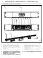
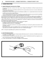
1.4 OPERATING ELEMENTS AND CONNECTIONS
1
2
3
4
5
6
6
8
6
7
8
9
9
9
1. MOUNTING HOLES for fixing the rack.
2. CONTROL PANEL with display and 4 buttons
used to access the control panel functions
and manage them.
3. GND POINT used for the grounding of the
device.
4. POWER IN (PowerCON IN) mains plug for
connection to a socket (100-240V~/50/60Hz)
via the supplied mains cable.
5. POWER OUT (PowerCON OUT): power output
for connection of multiple units in series.
6. DMX OUT (4-pole XLR): 1 = ground, 2 = DMX-,
3 = DMX+, 4 N/C.
7. DMX IN (4-pole XLR): 1 = ground, 2 = DMX-, 3
= DMX+, 4 N/C.
8. EtherCON connector Signal IN/OUT .
9. SAFETY EYE to attach safety cable.
Fig.4

7
DIGIDRIVERIP - DIGISTRIPIP50 - DIGISTRIPIP100
Fig.5
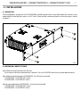
- 2 - INSTALLATION
2.1 MOUNTING
The management and power unit DIGIDRIVERIP should be placed on a non-flammable flat surface in any
orientation or fixed by four screws in a 19” rack. There are four mounting holes on the housing as shown
in figure 7.
2.2 MAXIMUM CABLE DISTANCE
Max cable distance between two fixtures:
• No maximum distance between the 2 devices. The last DIGISTRIP need to stay under 60m distance
Max cable distance between DIGIDRIVERIP - first fixture connected:
• DIGIDRIVERIP - DIGISTRIP100 = 60 m
• DIGIDRIVERIP - DIGISTRIP50 = 60 m
Max distance between DIGIDRIVERIP - last fixture connected:
• DIGIDRIVERIP - DIGISTRIP100 = 60 m
• DIGIDRIVERIP - DIGISTRIP50 = 60 m

DIGIDRIVERIP - DIGISTRIPIP50 - DIGISTRIPIP100
8
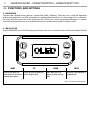
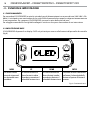
MENU
UP DOWN ENTER
Used to scroll down the
menu options or to return a
previous menu option
Scrolls up the list of options or
selects a higher value
Scrolls down the list of
options or selects a lower
value
Activates a menu option or a
selected value
- 3 - FUNCTIONS AND SETTINGS
3.1 OPERATION
Connect the supplied main cable to a socket (100-240V~/50-60Hz). Then the unit is ready for operation
and can be operated via a DMX controller or it independently performs its show program in succession.
To switch off, disconnect the mains plug from the socket. For a more convenient operation it is recom-
mended to connect the unit to a socket which can be switched on and off via a light switch.
3.1 BASIC SETUP
The DIGIDRIVERIP has an OLED display and 4 buttons for access to the functions of the control panel (fig.6).
Fig.6 - Functions of the buttons

9
DIGIDRIVERIP - DIGISTRIPIP50 - DIGISTRIPIP100
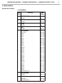
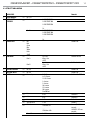
3.3 MENU STRUCTURE
MAIN LEVEL Remark
1 AUTO ADDRESS
ð
No - Yes
2 VIEM LINKED
FIXTURES
ð
Port A 1.DIGISTRIPIP100
2.DIGISTRIPIP100
3.DIGISTRIPIP050
…
18.
Port B 1.DIGISTRIPIP100
2.DIGISTRIPIP100
3.DIGISTRIPIP050
…
18.
3 LED OUTPUT
ð
Off
Red
Green
Blue
White
Fade
Scroll
Default: Off
4 PROTOCOL
ð
Port A
Art - Net
Kling - Net
sACN
Default: Art-Net
Port B
Art - Net
Kling - Net
sACN
Default: Art-Net
5 DISPLAY INVERSE
ð
No -Yes Default: No
6 FACTORY RESET
ð
No -Yes Default: Off
7 PORT A
ð
Personality 7-CH-Drive
8-CH-Fixture
13-CH-Fixture
2-Section
5-Section
10-Section
25-Section
50-Section
PixelTOPixel
Default : PixelTOPixel
ð
Net
0-127 Default: 0
ð
Subnet
0-15 Default: 0
ð
Universe
0-15 Default: 0
ð
sACN Universe
1-247 Default: 1
ð
IP Address
IP Address #1
…
IP Address #10
Art-net(IP 1-126.xxx.
xxx.xxx)
SACN(IP:1-255.xxx.
xxx.xxx)
Dmx Address 1 - 512 Default: 1

DIGIDRIVERIP - DIGISTRIPIP50 - DIGISTRIPIP100
10
7 PORT B
ð
Personality 7-CH-Drive
8-CH-Fixture
13-CH-Fixture
2-Section
5-Section
10-Section
25-Section
50-Section
PixelTOPixel
Default : PixelTOPixel
ð
Net 0-127 Default: 0
ð
Subnet 0-15 Default: 0
ð
Universe 0-15 Default: 0
ð
sACN Universe 1-247 Default: 1
ð
IP Address
IP Address #1
…
IP Address #10
Art-net(IP 1-126.xxx.
xxx.xxx)
SACN(IP:1-255.xxx.
xxx.xxx)
Dmx Address 1 - 512 Default: 1
8 SCREEN LOCK
ð
Yes-No
9 SOFTWARE VERSION
ð
Port A-V1.0
Port B-V1.0

11
DIGIDRIVERIP - DIGISTRIPIP50 - DIGISTRIPIP100
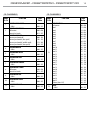
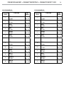
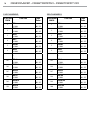
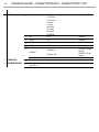
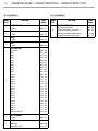
3.4 DMX CONTROL
Control Personalities
7 CHANNELS
MODE
FUNCTION DMX
Value
7 Ch
1
MASTER DIMMER
0~100% 000 - 255
2
RED
0~100% 000 - 255
3
GREEN
0~100% 000 - 255
4
BLUE
0~100% 000 - 255
5
AUTO PROGRAM
No Function
Auto 1
Auto 2
Auto 3
Auto 4
Auto 5
Auto 6
Auto 7
Auto 8
Auto 9
Auto 10
Auto 11
Auto 12
Auto 13
Auto 14
Auto 15
Auto 16
Auto 17
Auto 18
Auto 19
Auto 20
Auto 21
Auto 22
Auto 23
Auto 24
Auto 25
All Auto (Auto 1-25)
000 - 010
011 - 020
021 - 029
030 - 039
040 - 048
049 - 057
058 - 067
068 - 076
077 - 086
087 - 095
096 - 104
105 - 114
115 - 123
124 - 133
134 - 142
143 - 151
152 - 161
162 - 170
171 - 179
180 - 189
190 - 198
199 - 208
209 - 217
218 - 226
227 - 236
237 - 245
246 - 255
6
MASTER DIMMER
0~100% 000 - 255
7
STROBE
No function
Strobe Slow to Fast
000 - 010
011 - 255

DIGIDRIVERIP - DIGISTRIPIP50 - DIGISTRIPIP100
12
8 CHANNELS
MODE
FUNCTION DMX
Value
8 Ch
1
MASTER DIMMER
0~100% 000 - 255
2
RED
0~100% 000 - 255
3
GREEN
0~100% 000 - 255
4
BLUE
0~100% 000 - 255
5
AUTO PROGRAM
No Function
Auto 1
Auto 2
Auto 3
Auto 4
Auto 5
Auto 6
Auto 7
Auto 8
Auto 9
Auto 10
Auto 11
Auto 12
Auto 13
Auto 14
Auto 15
Auto 16
Auto 17
Auto 18
Auto 19
Auto 20
Auto 21
Auto 22
Auto 23
Auto 24
Auto 25
All Auto (Auto 1-25)
000 - 010
011 - 020
021 - 029
030 - 039
040 - 048
049 - 057
058 - 067
068 - 076
077 - 086
087 - 095
096 - 104
105 - 114
115 - 123
124 - 133
134 - 142
143 - 151
152 - 161
162 - 170
171 - 179
180 - 189
190 - 198
199 - 208
209 - 217
218 - 226
227 - 236
237 - 245
246 - 255
6
MASTER DIMMER
0~100% 000 - 255
7
STROBE
No function
Strobe Slow to Fast
000 - 010
011 - 255
8 CHANNELS
MODE
FUNCTION DMX
Value
8 Ch
8
DIMMER SPEED MODE
Dimmer speed mode off
Dimmer speed mode1 (fast speed)
Dimmer speed mode2 (middle speed)
Dimmer speed mode3 (slow speed)
000 - 101
102 - 152
153 - 203
204 - 255

13
DIGIDRIVERIP - DIGISTRIPIP50 - DIGISTRIPIP100
13 CHANNELS
MODE
FUNCTION DMX
Value
13 Ch
1
FOREGROUND DIMMER
0~100% 000 - 255
2
FOREGROUND STROBE
NO Function
Slow to Fast Strobe
000 - 010
011 - 255
3
FOREGROUND FADE
Dimmer speed mode off
Dimmer speed mode1 (fast speed)
Dimmer speed mode2 (middle speed)
Dimmer speed mode3 (slow speed)
000 - 101
102 - 152
153 - 203
204 - 255
4
FOREGROUND RED
0~100% 000 - 255
5
FOREGROUND GREEN
0~100% 000 - 255
6
FOREGROUND BLUE
0~100% 000 - 255
7
BACKGROUND DIMMER
0~100% 000 - 255
8
BACKGROUND STROBE
NO Function
Slow to Fast Strobe
000 - 010
011 - 255
9
BACKGROUND RED
0~100% 000 - 255
10
BACKGROUND GREEN
0~100% 000 - 255
11
BACKGROUND BLUE
0~100% 000 - 255
13 CHANNELS
MODE
FUNCTION DMX
Value
13 Ch
12
AUTO PROGRAM
No Function
Auto 1
Auto 2
Auto 3
Auto 4
Auto 5
Auto 6
Auto 7
Auto 8
Auto 9
Auto 10
Auto 11
Auto 12
Auto 13
Auto 14
Auto 15
Auto 16
Auto 17
Auto 18
Auto 19
Auto 20
Auto 21
Auto 22
Auto 23
Auto 24
Auto 25
All Auto (Auto 1-25)
000 - 010
011 - 020
021 - 029
030 - 039
040 - 048
049 - 057
058 - 067
068 - 076
077 - 086
087 - 095
096 - 104
105 - 114
115 - 123
124 - 133
134 - 142
143 - 151
152 - 161
162 - 170
171 - 179
180 - 189
190 - 198
199 - 208
209 - 217
218 - 226
227 - 236
237 - 245
246 - 255
13
SPEED
0~100% 000 - 255

DIGIDRIVERIP - DIGISTRIPIP50 - DIGISTRIPIP100
14
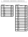
6 CHANNELS
2-SECTION
FUNCTION DMX
Value
6 Ch
1
RED 1
0~100% 000 - 255
2
GREEN 1
0~100% 000 - 255
3
BLUE 1
0~100% 000 - 255
4
RED 2
0~100% 000 - 255
5
GREEN 2
0~100% 000 - 255
6
BLUE 2
0~100% 000 - 255
15 CHANNELS
5-SECTION
FUNCTION DMX
Value
15 Ch
1
RED 1
0~100% 000 - 255
2
GREEN 1
0~100% 000 - 255
3
BLUE 1
0~100% 000 - 255
4
RED 2
0~100% 000 - 255
5
GREEN 2
0~100% 000 - 255
6
BLUE 2
0~100% 000 - 255
7
RED 3
0~100% 000 - 255
8
GREEN 3
0~100% 000 - 255
9
BLUE 3
0~100% 000 - 255
10
RED 4
0~100% 000 - 255
11
GREEN 4
0~100% 000 - 255
12
BLUE 4
0~100% 000 - 255
13
RED 5
0~100% 000 - 255
14
GREEN 5
0~100% 000 - 255
15
BLUE 5
0~100% 000 - 255

15
DIGIDRIVERIP - DIGISTRIPIP50 - DIGISTRIPIP100
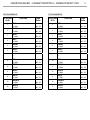
30 CHANNELS
10-SECTION
FUNCTION DMX
Value
30 Ch
1
RED 1
0~100% 000 - 255
2
GREEN 1
0~100% 000 - 255
3
BLUE 1
0~100% 000 - 255
4
RED 2
0~100% 000 - 255
5
GREEN 2
0~100% 000 - 255
6
BLUE 2
0~100% 000 - 255
...
25
RED 9
0~100% 000 - 255
26
GREEN 9
0~100% 000 - 255
27
BLUE 9
0~100% 000 - 255
28
RED 10
0~100% 000 - 255
29
GREEN 10
0~100% 000 - 255
30
BLUE 10
0~100% 000 - 255
75 CHANNELS
25-SECTION
FUNCTION DMX
Value
75 Ch
1
RED 1
0~100% 000 - 255
2
GREEN 1
0~100% 000 - 255
3
BLUE 1
0~100% 000 - 255
4
RED 2
0~100% 000 - 255
5
GREEN 2
0~100% 000 - 255
6
BLUE 2
0~100% 000 - 255
...
70
RED 24
0~100% 000 - 255
71
GREEN 24
0~100% 000 - 255
72
BLUE 24
0~100% 000 - 255
73
RED 25
0~100% 000 - 255
74
GREEN 25
0~100% 000 - 255
75
BLUE 25
0~100% 000 - 255

DIGIDRIVERIP - DIGISTRIPIP50 - DIGISTRIPIP100
16
150 CHANNELS
50-SECTION
FUNCTION DMX
Value
150 Ch
1
RED 1
0~100% 000 - 255
2
GREEN 1
0~100% 000 - 255
3
BLUE 1
0~100% 000 - 255
4
RED 2
0~100% 000 - 255
5
GREEN 2
0~100% 000 - 255
6
BLUE 2
0~100% 000 - 255
...
145
RED 49
0~100% 000 - 255
146
GREEN 49
0~100% 000 - 255
147
BLUE 49
0~100% 000 - 255
148
RED 50
0~100% 000 - 255
149
GREEN 50
0~100% 000 - 255
150
BLUE 50
0~100% 000 - 255
300 CHANNELS
PixelTOPixel
FUNCTION DMX
Value
300 Ch
1
RED 1
0~100% 000 - 255
2
GREEN 1
0~100% 000 - 255
3
BLUE 1
0~100% 000 - 255
4
RED 2
0~100% 000 - 255
5
GREEN 2
0~100% 000 - 255
6
BLUE 2
0~100% 000 - 255
...
295
RED 99
0~100% 000 - 255
296
GREEN 99
0~100% 000 - 255
297
BLUE 99
0~100% 000 - 255
298
RED 100
0~100% 000 - 255
299
GREEN 100
0~100% 000 - 255
300
BLUE 100
0~100% 000 - 255

17
DIGIDRIVERIP - DIGISTRIPIP50 - DIGISTRIPIP100
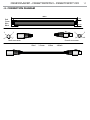
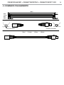
- 4 - CONNECTION DIAGRAM
Red
3
4
1
2
Green
Blue
Black
1-Red 2-Green
3-Blue
4-Black
Male connector Female connector
2cm2cm
3mm
3mm
100cm
3
4
1
2

DIGIDRIVERIP - DIGISTRIPIP50 - DIGISTRIPIP100
18
- 5 - MAINTENANCE
5.1 MAINTENANCE AND CLEANING THE UNIT
• Make sure the area below the installation place is free from unwanted persons during setup.
• All screws used for installing the device and any of its parts should be tightly fastened and should not
be corroded.
• Housings, fixations and installation spots (ceiling, trusses, suspensions) should be totally free from any
deformation.
• The main cables must be in impeccable condition and should be replaced immediately even when a
small problem is detected.
To maintain optimum performance and minimize wear, you should clean this product frequently. Usage
and environment are contributing factors in determining the cleaning frequency.
As a rule, clean this product at least twice a month. Dust build-up reduces light output performance and
can cause overheating. This can lead to reduced light source life and increased mechanical wear.
Cleaning the unit:
• Unplug the product.
• Wait until the product is at room temperature.
• Use a vacuum (or dry compressed air) and a soft brush to remove dust collected on the external vents
and accessible internal components.
• Clean all external surfaces with a mild solution of non-ammonia glass cleaner or isopropyl alcohol.
• Apply a solution directly to a soft, lint-free cotton cloth or a lens cleaning tissue.
NOTE - Do not open this product for cleaning or servicing.
5.2 FUSE REPLACEMENT
1. Disconnect this product from the power outlet.
2. Remove the safety cap by a screwdriver.
3. Replace the blown fuse with a fuse of the exact same type and rating.
4. Install the safety cap, and reconnect power.
Fig.7
La pagina si sta caricando...
La pagina si sta caricando...
La pagina si sta caricando...
La pagina si sta caricando...
La pagina si sta caricando...
La pagina si sta caricando...
La pagina si sta caricando...
La pagina si sta caricando...
La pagina si sta caricando...
La pagina si sta caricando...
La pagina si sta caricando...
La pagina si sta caricando...
La pagina si sta caricando...
La pagina si sta caricando...
La pagina si sta caricando...
La pagina si sta caricando...
La pagina si sta caricando...
La pagina si sta caricando...
La pagina si sta caricando...
La pagina si sta caricando...
La pagina si sta caricando...
La pagina si sta caricando...
La pagina si sta caricando...
La pagina si sta caricando...
-
 1
1
-
 2
2
-
 3
3
-
 4
4
-
 5
5
-
 6
6
-
 7
7
-
 8
8
-
 9
9
-
 10
10
-
 11
11
-
 12
12
-
 13
13
-
 14
14
-
 15
15
-
 16
16
-
 17
17
-
 18
18
-
 19
19
-
 20
20
-
 21
21
-
 22
22
-
 23
23
-
 24
24
-
 25
25
-
 26
26
-
 27
27
-
 28
28
-
 29
29
-
 30
30
-
 31
31
-
 32
32
-
 33
33
-
 34
34
-
 35
35
-
 36
36
-
 37
37
-
 38
38
-
 39
39
-
 40
40
-
 41
41
-
 42
42
-
 43
43
-
 44
44


ProLights DIGIDRIVERIP Manuale utente
- Categoria
- Proiettori
- Tipo
- Manuale utente
- Questo manuale è adatto anche per
in altre lingue
- English: ProLights DIGIDRIVERIP User manual
Documenti correlati
-
ProLights DIGIDRIVERIP Manuale utente
-
-
-
-
-
-
-