
Betriebsanleitung / Operating Instructions /
Instructions de Service / Manual de instrucciones /
Manuale d’uso e manutenzione
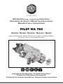
PILOT WA 705
Automatische Spritzpistolen / Automatic Spray Guns /
Pistolets de Pulvérisation Automatiques /
Pistolas de Pulverización Automáticas / Pistole a spruzzo automatiche
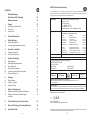
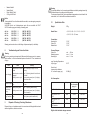
Modelle / Models / Modèles / Modelos / Modelli
ohne Innensteuerung / without internal control / sans commande intérieure
sin control interno / senza comando interno

32
PILOT WA 705
Stand: Januar 2010
27
26
25
24
23
22
21
20
19
5
6
7
8
10
9
11
12
13
14
15
17
16
18
28
30
29
ohne Innensteuerung
without internal control
sans commande intérieure
sin control interno
senza comando interno

Seite 6 - 23
Page 24 - 41
Page 42 - 59
Página 60 - 77
Pagina 78 - 95

76
EG/EU-Konformitätserklärung
Wir, der Gerätehersteller, erklären in alleiniger Verantwortung, dass das Produkt in der untenstehenden
Beschreibung den einschlägigen grundlegenden Sicherheits- und Gesundheitsanforderungen entspricht. Bei
einer nicht mit uns abgestimmten Änderung an dem Gerät oder bei einer unsachgemäßen Verwendung verliert
diese Erklärung ihre Gültigkeit.
Hersteller WALTHER Spritz- und Lackiersysteme GmbH
Kärntner Str. 18 - 30
D - 42327 Wuppertal
Tel.: +49(0)202 / 787 - 0
Fax: +49(0)202 / 787 - 2217
www.walther-pilot.de • e-mail: [email protected]
Typenbezeichnung
Automatische Spritzpistolen
PILOT WA 705-Serie ohne Innensteuerung
WA 705 (Standard-Ausführung) V 20 705
WA 715-U (Standard-Umlauf-Ausführung) V 20 715
WA 725-HVLP (Niederdruck-Ausführung) V 20 725
WA 735-HVLP-U (Niederdruck-Umlauf-Ausführung) V 20 735
WA 745-HVLP
PLUS
(Mitteldruck-Ausführung) V 20 745
WA 755-HVLP
PLUS
-U (Mitteldruck-Umlauf-Ausführung) V 20 755
WA 708-K (Standard-Kleber-Ausführung) V 20 708
WA 718-U-K (Standard-Umlauf-Kleber-Ausf.) V 20 718
WA 728-HVLP-K (Niederdruck-Kleber-Ausführung) V 20 728
WA 738-HVLP-U-K (Niederdruck-Umlauf-Kleber-Ausf.) V 20 738
Verwendungszweck Verarbeitung spritzbarer Materialien
Angewandte Normen und Richtlinien
EG-Maschinenrichtlinien 2006/42/EG
2014/34/EU (ATEX Richtlinien)
DIN EN ISO 12100
DIN EN 1953 DIN EN 13463-1
DIN EN 1127-1 DIN EN 13463-5
Spezifikation im Sinne der Richtlinie 2014/34/EU
Kategorie 2 Gerätebezeichnung
II 2 G c T 5
Tech.File,Ref.:
2414
Bevollmächtigt mit der Zusammenstellung der technischen Unterlagen:
Nico Kowalski, WALTHER Spritz- und Lackiersysteme GmbH, Kärntner Str. 18 - 30
D- 42327 Wuppertal
Besondere Hinweise :
Das Produkt ist zum Einbau in ein anderes Gerät bestimmt. Die Inbetriebnahme ist so lange untersagt, bis
die Konformität des Endproduktes mit der Richtlinie 2006/42/EG festgestellt ist.
Wuppertal, den 02. November 2016
Name: Torsten Bröker
Stellung im Betrieb: Leiter der Konstruktion und Entwicklung
Diese Erklärung ist keine Zusicherung von Eigenschaften im Sinne der Produkthaftung. Die Sicherheitshinweise
der Produktdokumentation sind zu beachten.
ppa.
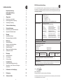
Inhaltsverzeichnis
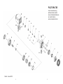
Explosionszeichnung 2
Konformitätserklärung 7
Ersatzteilliste 8
1 Allgemeines 12
1.1 Kennzeichnung der Modelle 12
1.2 Bestimmungsgemäße Verwendung 12
1.3 Sachwidrige Verwendung 13
2 Technische Beschreibung 13
3 Sicherheitshinweise 14
3.1 Kennzeichnung der Sicherheitshinweise 14
3.2 Allgemeine Sicherheitshinweise 14
4 Montage 15
4.1 Spritzpistole befestigen 15
4.2 Versorgungsleitungen anschließen 15
5 Bedienung 16
5.1 Sicherheitshinweise 16
5.2 Inbetrieb- und Außerbetriebsetzen 16
5.3 Spritzbildprobe erzeugen 16
5.4 Spritzbild verändern 17
5.5 Mängel eines Spritzbildes beheben 18
5.6 Spritzpistole umrüsten 18
6 Reinigung 19
6.1 Sicherheitshinweise 19
6.2 Grundreinigung 19
6.3 Routinereinigung 20
7 Instandsetzung 21
7.1 Undichte Nadelpackung austauschen 21
7.2 Materialdüse, -nadel, Federn und Dichtungen 21
austauschen
8 Fehlersuche und -beseitigung 22
9 Entsorgung 22
10 Technische Daten 23

98
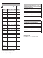
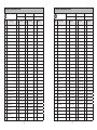
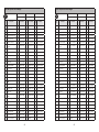
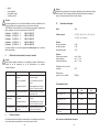
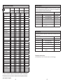
Ersatzteilliste:
WA 705 WA 715-U WA 725-HVLP
V 20 705 V 20 715 V 20 725
Pos.
Bezeichnung
Stck.
Artikelnummer
Stck.
Artikelnummer
Stck.
Artikelnummer
1 Luftkopfmutter kompl. 1 V 20 700 05 000 1 V 20 700 05 000 1 V 20 700 05 000
2 Luftkopf* 1 V 10 700 35 XX8* 1 V 10 700 35 XX8* 1 V 10 700 37 XXX*
3 Materialdüse* 1 V 10 700 40 XX3* 1 V 10 700 40 XX3* 1 V 10 700 40 XX3*
5 Luftverteilerring 1 V 20 700 04 000 1 V 20 700 04 000 1 V 20 700 04 100
6 Innensechskantschraube 4 V 20 700 13 003 4 V 20 700 13 003 4 V 20 700 13 003
7 Pistolenvorderkörper komp. 1 V 20 700 03 000 1 V 20 710 03 000 1 V 20 700 03 000
8 Stift für Luftkappenfixierung 1 V 20 700 02 303 1 V 20 700 02 303 1 V 20 700 02 303
9 Arretierfeder 1 V 20 700 02 403 1 V 20 700 02 403 1 V 20 700 02 403
10 Gewindestift 1 V 20 310 01 503 1 V 20 310 01 503 1 V 20 310 01 503
11 O-Ring 2 V 09 103 64 009 2 V 09 103 64 009 2 V 09 103 64 009
12 Nadelpackung kompl. 1 V 09 001 72 000 1 V 09 001 72 000 1 V 09 001 72 000
13 Druckstück 1 V 10 361 07 000 1 V 10 361 07 000 1 V 10 361 07 000
14 Packungsfeder 1 V 20 510 12 003 1 V 20 510 12 003 1 V 20 510 12 003
15 Packungsschraube 1 V 20 510 11 003 1 V 20 510 11 003 1 V 20 510 11 003
16 Dichtschraube 1 V 22 650 43 100 1 V 22 650 43 100 1 V 22 650 43 100
17 Nutring 1 V 09 220 30 000 1 V 09 220 30 000 1 V 09 220 30 000
18 Kolbengehäuse kompl. 1 V 20 705 01 000 1 V 20 705 01 000 1 V 20 705 01 000
19 Dichtsatz 1 V 20 700 07 000 1 V 20 700 07 000 1 V 20 700 07 000
20 Kolben 1 V 20 705 08 000 1 V 20 705 08 000 1 V 20 705 08 000
21 Kolbenfeder 1 V 20 606 11 000 1 V 20 606 11 000 1 V 20 606 11 000
22 Gewindebuchse kompl. 1 V 20 700 09 000 1 V 20 700 09 000 1 V 20 700 09 000
23 Materialnadel kompl.* 1 V 20 705 30 XX3* 1 V 20 705 30 XX3* 1 V 20 705 30 XX3*
24 Nadelfeder 1 V 20 510 29 003 1 V 20 510 29 003 1 V 20 510 29 003
25 Kappe kompl. 1 V 20 700 10 000 1 V 20 700 10 000 1 V 20 700 10 000
26 Zugstange kompl. 1 V 20 510 34 000 1 V 20 510 34 000 1 V 20 510 34 000
27 Steckverschraubung 2 V 66 101 53 015 2 V 66 101 53 015 2 V 66 101 53 015
28 Steckverschraubung 1 V 66 101 53 013 1 V 66 101 53 013 1 V 66 101 53 013
29 Doppelnippel G1/4 1 V 00 101 01 003 2 V 00 101 01 003 1 V 00 101 01 003
30 Verschlussstopfen 1 V 20 540 40 003 entfällt 1 V 20 540 40 003
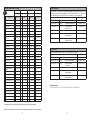
Ersatzteilliste:
WA 735-HVLP-U WA 745-HVLP
PLUS
WA 755-HVLP
PLUS
-U
V 20 735 V 20 745 V 20 755
Pos.
Bezeichnung
Stck.
Artikelnummer
Stck.
Artikelnummer
Stck.
Artikelnummer
1 Luftkopfmutter kompl. 1 V 20 700 05 000 1 V 20 700 05 000 1 V 20 700 05 000
2 Luftkopf* 1 V 10 700 37 XXX* 1 V 10 700 36 XXX* 1 V 10 700 36 XXX*
3 Materialdüse* 1 V 10 700 40 XX3* 1 V 10 700 40 XX3* 1 V 10 700 40 XX3*
5 Luftverteilerring 1 V 20 700 04 100 1 V 20 700 04 100 1 V 20 700 04 100
6 Innensechskantschraube 4 V 20 700 13 003 4 V 20 700 13 003 4 V 20 700 13 003
7 Pistolenvorderkörper komp. 1 V 20 710 03 000 1 V 20 700 03 000 1 V 20 710 03 000
8 Stift für Luftkappenfixierung 1 V 20 700 02 303 1 V 20 700 02 303 1 V 20 700 02 303
9 Arretierfeder 1 V 20 700 02 403 1 V 20 700 02 403 1 V 20 700 02 403
10 Gewindestift 1 V 20 310 01 503 1 V 20 310 01 503 1 V 20 310 01 503
11 O-Ring 2 V 09 103 64 009 2 V 09 103 64 009 2 V 09 103 64 009
12 Nadelpackung kompl. 1 V 09 001 72 000 1 V 09 001 72 000 1 V 09 001 72 000
13 Druckstück 1 V 10 361 07 000 1 V 10 361 07 000 1 V 10 361 07 000
14 Packungsfeder 1 V 20 510 12 003 1 V 20 510 12 003 1 V 20 510 12 003
15 Packungsschraube 1 V 20 510 11 003 1 V 20 510 11 003 1 V 20 510 11 003
16 Dichtschraube 1 V 22 650 43 100 1 V 22 650 43 100 1 V 22 650 43 100
17 Nutring 1 V 09 220 30 000 1 V 09 220 30 000 1 V 09 220 30 000
18 Kolbengehäuse kompl. 1 V 20 705 01 000 1 V 20 705 01 000 1 V 20 705 01 000
19 Dichtsatz 1 V 20 700 07 000 1 V 20 700 07 000 1 V 20 700 07 000
20 Kolben 1 V 20 705 08 000 1 V 20 705 08 000 1 V 20 705 08 000
21 Kolbenfeder 1 V 20 606 11 000 1 V 20 606 11 000 1 V 20 606 11 000
22 Gewindebuchse kompl. 1 V 20 700 09 000 1 V 20 700 09 000 1 V 20 700 09 000
23 Materialnadel kompl.* 1 V 20 705 30 XX3* 1 V 20 705 30 XX3* 1 V 20 705 30 XX3*
24 Nadelfeder 1 V 20 510 29 003 1 V 20 510 29 003 1 V 20 510 29 003
25 Kappe kompl. 1 V 20 700 10 000 1 V 20 700 10 000 1 V 20 700 10 000
26 Zugstange kompl. 1 V 20 510 34 000 1 V 20 510 34 000 1 V 20 510 34 000
27 Steckverschraubung 2 V 66 101 53 015 2 V 66 101 53 015 2 V 66 101 53 015
28 Steckverschraubung 1 V 66 101 53 013 1 V 66 101 53 013 1 V 66 101 53 013
29 Doppelnippel G1/4 2 V 00 101 01 003 1 V 00 101 01 003 2 V 00 101 01 003
30 Verschlussstopfen entfällt 1 V 20 540 40 003 entfällt

1110
Reparatursets
WALTHER PILOT hält für die Automatik-Spritzpistolen PILOT WA 705 - WA 755 HVLP
PLUS
-U und
die Ausführung für die Kleberverarbeitung PILOT WA 708-K - WA 738 HVLP-U-K Reparatur-
sets bereit, die sämtliche Verschleißteile enthalten.
Artikelnummer
PILOT WA 705/ 715 Standard-Version V 16 207 05 XX3
PILOT WA 725 / 735 HVLP / Niederdruck-Version V 16 207 25 XX3
PILOT WA 745 / 755 HVLP
PLUS
/ Mitteldruck-Version V 16 207 45 XX3
PILOT WA 708 / 718 Standard-Kleber-Version V 16 207 08 XX3
PILOT WA 728 / 738 HVLP / Niederdruck-Kleber-Version V 16 207 28 XX3
Düseneinlage
Die Düseneinlagen bestehen aus Luftkopf, Materialdüse und Materialnadel
Artikelnummer
PILOT WA 705/ 715 Standard-Version V 15 207 05 XX3
PILOT WA 725 / 735 HVLP / Niederdruck-Version V 15 207 25 XX3
PILOT WA 745 / 755 HVLP
PLUS
/ Mitteldruck-Version V 15 207 45 XX3
PILOT WA 708 / 718 Standard-Kleber-Version V 15 207 08 XX3
PILOT WA 728 / 738 HVLP / Niederdruck-Kleber-Version V 15 207 28 XX3
Düsenausstattung nach Wahl:
▪ 0,3 ▪ 0,5 ▪ 0,8 ▪ 1,0 ▪ 1,2 ▪ 1,5 ▪ 1,8 ▪ 2,0 ▪ 2,2 ▪ 2,5 ▪ 3,0 ▪ 3,5 mm ø
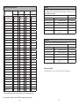
Ersatzteilliste:
WA 708-Kleber WA 718-U-Kleber WA 728-HVLP-
Kleber
WA 738-HVLP-U-
Kleber
V 20 708 V 20 718 V 20 728 V 20 738
Pos.
Bezeichnung
Stck.
Artikelnummer
Stck.
Artikelnummer
Stck.
Artikelnummer
Stck.
Artikelnummer
1 Luftkopfmutter kompl.
1 V 20 700 05 000 1 V 20 700 05 000 1 V 20 700 05 000 1 V 20 700 05 000
2 Luftkopf*
1 V 10 711 35 XX5* 1 V 10 711 35 XX5* 1 V 10 711 35 XX5* 1 V 10 711 35 XX5*
3 Materialdüse*
1 V 10 711 40 XX3* 1 V 10 711 40 XX3* 1 V 10 711 40 XX3* 1 V 10 711 40 XX3*
5 Luftverteilerring
1 V 20 700 04 000 1 V 20 700 04 000 1 V 20 700 04 100 1 V 20 700 04 100
6 Innensechskantschraube
4 V 20 700 13 003 4 V 20 700 13 003 4 V 20 700 13 003 4 V 20 700 13 003
7
Pistolenvorderkörper komp. 1 V 20 700 03 000 1 V 20 710 03 000 1 V 20 700 03 000 1 V 20 710 03 000
8
Stift für Luftkappenfixierung 1 V 20 700 02 303 1 V 20 700 02 303 1 V 20 700 02 303 1 V 20 700 02 303
9 Arretierfeder
1 V 20 700 02 403 1 V 20 700 02 403 1 V 20 700 02 403 1 V 20 700 02 403
10 Gewindestift
1 V 20 310 01 503 1 V 20 310 01 503 1 V 20 310 01 503 1 V 20 310 01 503
11 O-Ring
2 V 09 103 64 009 2 V 09 103 64 009 2 V 09 103 64 009 2 V 09 103 64 009
12 Nadelpackung kompl.
1 V 09 001 72 000 1 V 09 001 72 000 1 V 09 001 72 000 1 V 09 001 72 000
13 Druckstück
1 V 10 361 07 000 1 V 10 361 07 000 1 V 10 361 07 000 1 V 10 361 07 000
14 Packungsfeder
1 V 20 510 12 003 1 V 20 510 12 003 1 V 20 510 12 003 1 V 20 510 12 003
15 Packungsschraube
1 V 20 510 11 003 1 V 20 510 11 003 1 V 20 510 11 003 1 V 20 510 11 003
16 Dichtschraube
1 V 22 650 43 100 1 V 22 650 43 100 1 V 22 650 43 100 1 V 22 650 43 100
17 Nutring
1 V 09 220 30 000 1 V 09 220 30 000 1 V 09 220 30 000 1 V 09 220 30 000
18 Kolbengehäuse kompl.
1 V 20 705 01 000 1 V 20 705 01 000 1 V 20 705 01 000 1 V 20 705 01 000
19 Dichtsatz
1 V 20 700 07 000 1 V 20 700 07 000 1 V 20 700 07 000 1 V 20 700 07 000
20 Kolben
1 V 20 705 08 000 1 V 20 705 08 000 1 V 20 705 08 000 1 V 20 705 08 000
21 Kolbenfeder
1 V 20 606 11 000 1 V 20 606 11 000 1 V 20 606 11 000 1 V 20 606 11 000
22 Gewindebuchse kompl.
1 V 20 700 09 000 1 V 20 700 09 000 1 V 20 700 09 000 1 V 20 700 09 000
23 Materialnadel kompl.*
1 V 20 728 30 XX3* 1 V 20 728 30 XX3* 1 V 20 728 30 XX3* 1 V 20 728 30 XX3*
24 Nadelfeder
1 V 20 510 29 003 1 V 20 510 29 003 1 V 20 510 29 003 1 V 20 510 29 003
25 Kappe kompl.
1 V 20 700 10 000 1 V 20 700 10 000 1 V 20 700 10 000 1 V 20 700 10 000
26 Zugstange kompl.
1 V 20 510 34 000 1 V 20 510 34 000 1 V 20 510 34 000 1 V 20 510 34 000
27 Steckverschraubung
2 V 66 101 53 015 2 V 66 101 53 015 2 V 66 101 53 015 2 V 66 101 53 015
28 Steckverschraubung
1 V 66 101 53 013 1 V 66 101 53 013 1 V 66 101 53 013 1 V 66 101 53 013
29 Doppelnippel G1/4
1 V 00 101 01 003 2 V 00 101 01 003 1 V 00 101 01 003 2 V 00 101 01 003
30 Verschlussstopfen
1 V 20 540 40 003 entfällt 1 V 20 540 40 003 entfällt
* Bei Ersatzteillieferungen bitte entsprechende Größe angeben.
Wir empfehlen, alle fettgedruckten Teile (Verschleißteile) auf Lager zu halten.

1312
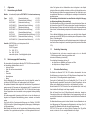
1 Allgemeines
1.1 Kennzeichnung der Modelle
Modelle: Automatische Spritzpistolen PILOT WA 705 - Serie ohne Innensteuerung
Typen: WA 705 (Standard-Ausführung) V 20 705
WA 715-U (Standard-Umlauf-Ausführung) V 20 715
WA 725-HVLP (Niederdruck-Ausführung) V 20 725
WA 735-HVLP-U (Niederdruck-Umlauf-Ausführung) V 20 735
WA 745-HVLP
PLUS
(Mitteldruck-Ausführung) V 20 745
WA 755-HVLP
PLUS
-U (Mitteldruck-Umlauf-Ausführung) V 20 755
WA 708-K (Standard-Kleber-Ausführung) V 20 708
WA 718-U-K (Standard-Umlauf-Kleber-Ausführung) V 20 718
WA 728-HVLP-K (Niederdruck-Kleber-Ausführung) V 20 728
WA 738-HVLP-U-K (Niederdruck-Umlauf-Kleber-Ausf.) V 20 738
Hersteller: WALTHER Spritz- und Lackiersysteme GmbH
Kärntner Str. 18-30
D-42327 Wuppertal
Tel.: 0202 / 787-0
Fax: 0202 / 787-2217
www.walther-pilot.de • Email:[email protected]
1.2 Bestimmungsgemäße Verwendung
Die automatischen Spritzpistolen der Baureihe PILOT WA 705 dienen ausschließlich
der Verarbeitung spritzbarer Medien, wie z. B.:
• Lacke und Farben
• Fette, Öle und Korrosionsschutzmittel
• Kleber
• Trennmittel
• Keramikglasuren
• Beizen
Sind die Materialien, die Sie verspritzen wollen, hier nicht aufgeführt, wenden Sie
sich bitte an WALTHER Spritz- und Lackiersysteme GmbH, Wuppertal.
Die spritzbaren Materialien dürfen lediglich auf Werkstücke bzw. Gegenstände auf-
getragen werden. Die Temperatur des Spritzmaterials darf 80°C grundsätzlich nicht
überschreiten. Die Modelle der Baureihe PILOT WA 7XX Serie sind keine handge-
führten Spritzpistolen und müssen deshalb an einer geeigneten Halterung befestigt
werden.
Die bestimmungsgemäße Verwendung schließt auch ein, dass alle Hinweise und
Angaben der vorliegenden Betriebsanleitung gelesen, verstanden und beachtet
werden.
Das Gerät erfüllt die Explosionsschutz-Forderungen der Richtlinie 2014/34/EU
(ATEX) für die auf dem Typenschild angegebene Explosionsgruppe, Gerätekategorie,
und Temperaturklasse.
Beim Betreiben des Gerätes sind die Vorgaben dieser Betriebsanleitung unbedingt
einzuhalten. Die vorgeschriebenen Inspektions- und Wartungsintervalle sind einzu-
halten. Die Angaben auf den Geräteschildern bzw. die Angaben in dem Kapitel
technische Daten sind unbedingt einzuhalten und dürfen nicht überschritten werden.
Eine Überlastung des Gerätes muss ausgeschlossen sein. Das Gerät darf in explo-
sionsgefährdeten Bereichen nur nach Maßgabe der zuständigen Aufsichtsbehörde
eingesetzt werden.
Der zuständigen Aufsichtsbehörde bzw. dem Betreiber obliegt die Festlegung
der Explosionsgefährdung (Zoneneinteilung).
Es ist betreiberseitig zu prüfen und sicherzustellen, dass alle technischen Daten und
die Kennzeichnung gemäß ATEX mit den notwendigen Vorgaben übereinstimmen.
Bei Anwendungen, bei denen der Ausfall des Gerätes zu einer Personengefährdung
führen könnte, sind betreiberseitig entsprechende Sicherheitsmaßnahmen vorzuse-
hen.
Falls im Betrieb Auffälligkeiten erkannt werden, muss das Gerät sofort stillgesetzt
werden und es ist mit WALTHER Spritz- und Lackiersysteme Rücksprache zu halten.
Erdung / Potentialausgleich
Es muss sichergestellt werden, dass die Spritzpistole separat oder in Verbindung mit
dem Gerät auf dem sie aufgebaut ist, ausreichend geerdet ist (maximaler Widerstand
10
6
Ω).
1.3 Sachwidrige Verwendung
Die Spritzpistole darf nicht anders verwendet werden, als es im Abschnitt
1.2 Bestimmungsgemäße Verwendung geschrieben steht.
Jede andere Verwendung ist sachwidrig.
Zur sachwidrigen Verwendung gehören z.B.:
• das Verspritzen von Materialien auf Personen und Tiere
• das Verspritzen von flüssigem Stickstoff.
2 Technische Beschreibung
Die Modelle der Baureihe PILOT WA 7XX arbeiten vollautomatisch über eine
Druckluftsteuerung und werden über ein 3/2-Wege-Steuerventil angesteuert. Dazu
können Hand-, Fuß-oder Magnetventile eingesetzt werden.
Zuerst wird die Zerstäuberluft (Rund- und Breitstrahlluft) (Pos. 27) über ein 3/2
Wege-Steuerventil zugeschaltet. Danach wird die Steuerluft angesteuert, die den
Kolben und die Materialnadel zurück drückt, um die Materialzufuhr zu öffnen.
Bei den Modellen PILOT WA 7XX wird die Form des Spritzstrahls (flach / breit / rund)
über die beiden Druckluftregler in der Anlage eingestellt.
Wird die Steuerluft durch das 3/2-Wege-Steuerventil unterbrochen, bewegt der
Federdruck den Kolben und die Materialnadel in ihrer Ausgangsstellung zurück und
verschließt die Materialzufuhr zur Materialdüse. Anschließend wird die Zerstäuberluft
abgeschaltet.
Die Materialdurchflussmenge wird bei allen Modellen über den Materialdruck und
durch Begrenzung des Öffnungsweges der Materialnadel an der Kappe (Pos. 25)
eingestellt. Der Materialdurchfluss der Automatik-Spritzpistolenserie
PILOT WA 7XX kann auch von Hand mit Hilfe der Zugstange (Pos. 26) geöffnet
werden, um dadurch z. B. eine verstopfte Materialdüse zu reinigen.

1514
Die Spritzpistolen der PILOT WA 7XX-Serie können an Materialdruckgefäßen und
Pumpensystemen angeschlossen werden.
Die Modelle PILOT WA 715-U / WA 735-HVLP-U / WA 755-HVLP
PLUS
-U /.WA 718-U-K
und WA 738-HVLP-U-K mit Anschluss für Farbumlauf können in eine Anlage mit
Zirkulation eingebunden werden.
Die Modelle PILOT WA 725-HVLP / WA 735 HVLP-U / WA 728 HVLP-K und
WA 738 HVLP-U-K sind reine Niederdruck-Spritzpistolen und arbeiten mit einem
Spritzluftdruck von 0,7 bar bei einem Eingangsluftdruck von 4,5 bar.
Bei den Modelle PILOT WA 745-HVLP
PLUS
und WA 755 HVLP
PLUS
-U beträgt der
Eingangsluftdruck von 3,0 bis 3,3 bar für einen Spritzluftdruck von 1,2 bis 1,4 bar.
3 Sicherheitshinweise
3.1 Kennzeichnung der Sicherheitshinweise
Warnung
Das Piktogramm und die Dringlichkeitsstufe „Warnung“ kennzeichnen eine mögliche
Gefahr für Personen. - Mögliche Folgen: schwere oder leichte Verletzungen.
Achtung
Das Piktogramm und die Dringlichkeitsstufe „Achtung“ kennzeichnen eine mögliche
Gefahr für Sachwerte. - Mögliche Folgen: Beschädigung von Sachen.
Hinweis
Das Piktogramm und die Dringlichkeitsstufe „Hinweis“ kennzeichnen zusätzliche
Informationen für das sichere und effiziente Arbeiten mit der Spritzpistole.
3.2 Allgemeine Sicherheitshinweise
► Die einschlägigen Unfallverhütungsvorschriften sowie die sonstigen anerkann-
ten sicherheitstechnischen und arbeitsmedizinischen Regeln sind einzuhalten.
► Benutzen Sie die Spritzpistole nur in gut belüfteten Räumen. Im Arbeitsbereich
ist Feuer, offenes Licht und Rauchen verboten. Beim Verspritzen leichtentzünd-
licher Materialien (z. B. Lacke, Kleber, Reinigungsmittel usw.) besteht erhöhte
Gesundheits-, Explosions- und Brandgefahr.
► Es muss sichergestellt werden, dass die Spritzpistole separat oder in Verbindung
mit dem Gerät auf dem sie aufgebaut ist, ausreichend geerdet ist (
max.
Widerstand
10
6
Ω).
► Schalten Sie vor jeder Wartung und Instandsetzung die Luft- und Materialzufuhr
zur Spritzpistole drucklos - Verletzungsgefahr.
► Halten Sie beim Verspritzen von Materialien keine Hände oder andere
Körperteile vor die unter Druck stehende Düse der Spritzpistole
- Verletzungsgefahr.
► Richten Sie die Spritzpistole nicht auf Personen und Tiere - Verletzungsgefahr.
► Beachten Sie die Verarbeitungs- und Sicherheitshinweise der Hersteller von
Spritzmaterial und Reinigungsmittel. Insbesondere aggressive und ätzende
Materialien können gesundheitliche Schäden verursachen.
► Tragen Sie im Arbeitsbereich der Spritzpistole einen Gehörschutz. Der erzeugte
Schallpegel der Spritzpistole von ca. 86 dB (A) kann einen Gehörschaden ver-
ursachen.
► Die partikelführende Abluft ist vom Arbeitsbereich und Betriebspersonal fernzu-
halten. Tragen Sie dennoch vorschriftsgemäßen Atemschutz und vorschriftsge-
mäße Arbeitskleidung, wenn Sie mit der Spritzpistole Materialien verarbeiten.
Umherschwebende Partikel gefährden Ihre Gesundheit.
► Achten Sie stets darauf, dass nach den Montage- und Wartungsarbeiten alle
Muttern und Schrauben fest angezogen sind.
► Verwenden Sie nur Original-Ersatzteile, da WALTHER nur für diese eine siche-
re und einwandfreie Funktion garantieren kann.
► Bei Nachfragen zur gefahrlosen Benutzung der Spritzpistole sowie der darin
verwendeten Materialien, wenden Sie sich bitte an WALTHER Spritz- und
Lackiersysteme GmbH, D-42327 Wuppertal.
4 Montage
Die Spritzpistole ist werkseitig komplett montiert. Bevor Sie die Spritzpistole in
Betrieb setzen können, sind die folgenden Tätigkeiten durchzuführen:
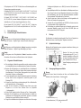
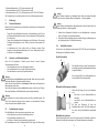
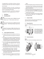
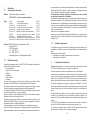
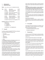
4.1 Spritzpistole befestigen
Befestigen Sie die Spritzpistole an einer geeigneten, standsicheren Halterung, wie
im folgenden Beispiel beschrieben:
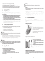
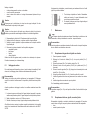
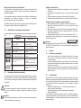
4.2 Versorgungsleitungen anschließen
Warnung
Achten Sie darauf, dass die Anschlüsse der Steuer- und Zerstäuberluft (Rund/
Breitstrahl) nicht vertauscht werden - Verletzungsgefahr.
1 = Materialanschluss (G 1/4“)
2 = Steuerluftanschluss (G 1/8“) gekennzeichnet mit ST
Benutzen Sie hierzu die beiden
Durchgangsbohrungen Ø 5,3 mm (1)
mit einem Lochabstand von 28 mm und
die beiden Gewindebohrungen M5 mit
einem Lochabstand von 28 mm (2)
Andere Befestigungsvorrichtungen auf
Anfrage.
5
5
3
2
1
4
(2) (1)

1716
3 = Breitstrahlluftanschluss (G 1/8") gekennzeichnet mit B
4 = Rundstrahlluftanschluss (G 1/8") gekennzeichnet mit R
5 = Materialanschlüsse (G 1/4“) für Umlaufversionen der PILOT WA 7XX Modelle
Die Spritzpistole ist nun vollständig montiert und kann in Betrieb gesetzt werden.
5 Bedienung
5.1 Sicherheitshinweise
Beachten Sie bei der Bedienung der Spritzpistole insbesondere die nachfolgenden
Sicherheitshinweise!
• Tragen Sie vorschriftsmäßigen Atemschutz und Arbeitskleidung, wenn Sie mit
der Spritzpistole Materialien verspritzen. Umherschwebende Partikel gefährden
Ihre Gesundheit.
• Tragen Sie im Arbeitsbereich der Spritzpistole einen Gehörschutz. Der erzeugte
Schallpegel der Spritzpistole von ca. 86 dB (A) kann einen Gehörschaden ver-
ursachen.
• Im Arbeitsbereich ist Feuer, offenes Licht und Rauchen verboten. Beim
Verspritzen leicht entzündbarer Materialien (z. B. Lacke, Kleber) besteht erhöh-
te Explosions- und Brandgefahr.
5.2 Inbetrieb- und Außerbetriebsetzen
Bevor Sie die Spritzpistole in Betrieb setzen können, müssen folgende
Voraussetzungen erfüllt sein:
• Der Steuerluftdruck muss an der Spritzpistole anstehen
• Der Zerstäuberluftdruck muss an der Spritzpistole anstehen
• Der Materialdruck muss an der Spritzpistole anstehen.
Achtung
Der Materialdruck darf nicht höher eingestellt sein als • 8 bar, da sonst kein funkti-
onssicherer Betrieb der Spritzpistole gewährleistet ist.
Stellen Sie den Steuerluftdruck auf • mindestens 4,5 bar, damit die Spritzpistole in
Betrieb gesetzt werden kann.
Sie können die Spritzpistole in und außer Betrieb setzen, indem Sie das 3/2-Wege-
Steuerventil betätigen (siehe Betriebsanleitung des Anlagenherstellers).
Warnung
Die Spritzpistole muss nach Arbeitsende immer drucklos geschaltet werden. Die
unter Druck stehenden Leitungen können platzen und nahestehende Personen
durch das ausströmende Material verletzen.
5.3 Spritzbildprobe erzeugen
Eine Spritzbildprobe sollte immer dann erzeugt werden, wenn
• die Spritzpistole zum ersten Mal in Betrieb gesetzt wird
• das Spritzmaterial ausgetauscht wird
• die Pistole zur Wartung oder Instandsetzung zerlegt wurde.
Die Spritzbildprobe kann auf ein Probewerkstück, Blech, Pappe oder Papier abge-
geben werden.
Warnung
Halten Sie beim Verspritzen von Materialien keine Hände oder andere Körperteile
vor die unter Druck stehende Düse der Spritzpistole - Verletzungsgefahr.
Warnung
Achten Sie beim Inbetriebsetzen der Spritzpistole darauf, dass sich keine Person im
Spritzbereich befindet - Verletzungsgefahr
1. Setzen Sie die Spritzpistole in Betrieb, um eine Spritzbildprobe zu erzeugen
(siehe 5.2 Inbetrieb- und Außerbetriebsetzen).
2. Kontrollieren Sie die Spritzbildprobe und verändern Sie ggf. die Einstellungen an
der Spritzpistole (siehe 5.4 Spritzbild verändern).
5.4 Spritzbild verändern
Sie können an den Spritzpistolen der Baureihe PILOT WA 705 durch die folgenden
Einstellungen das Spritzbild verändern:
Spritzluft einstellen
Materialdurchflussmenge einstellen
Materialdruck regulieren
Diese Einstellung können Sie nur an der Pumpe oder am Druckbehälter vornehmen.
Beachten Sie dabei die Anweisungen und Sicherheitshinweise des Herstellers.
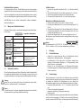
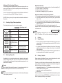
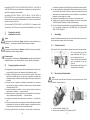
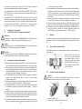
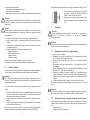
Das Spritzbild wird über einen Druckluftregler in
der Anlage eingestellt (siehe Betriebsanleitung des
Anlagen-Herstellers).
Der Anschluss (B) ist für die Breitstrahlluft, der
Anschluss (R) ist für die Rundstrahlluft.
B
R
Drehen Sie die Kappe (1) aus der Grundeinstel-
lung
• nach innen, um den Materialdurchfluss zu
verringern.
• nach außen, um den Materialdurchfluss zu
erhöhen.
Mit Hilfe der Zugstange (2) kann der
Materialdurchfluss durch die Düse betätigt wer-
den, ohne dass die Zerstäuberluft eingeschaltet
wird.
2
1

1918
Zerstäuberluftdruck regulieren
Der Zerstäuberluftdruck wird am Druckluft-Reduzierventil der Kompressoranlage
eingestellt. Beachten Sie die Anweisungen und Sicherheitshinweise des Herstellers.
Wenn Sie das Spritzbild über die bereits erwähnten Möglichkeiten hinaus verändern
wollen, muss die Spritzpistole umgerüstet werden (siehe 5.6 Spritzpistole umrüsten).
WALTHER bietet dazu eine Vielzahl unterschiedlicher Luftkopf-/ Materialdüse-/
Nadel-Kombinationen an.
5.5 Mängel eines Spritzbildes beheben
Die folgende Tabelle zeigt Ihnen, mit welchen Einstellungen Sie das Spritzbild beein-
flussen können.
Spritzbildprobe Abweichung erforderliche Einstellung
Spritzbild ist in der Mitte zu
dick
• breitere Spritzstrahlform einstellen
Spritzbild ist an den Enden
zu dick
• rundere Spritzstrahlform einstellen
Spritzbild ist ziemlich
grobtropfig
• Zerstäuberluftdruck erhöhen
Materialauftrag ist in der
Spritzbildmitte sehr dünn
• Zerstäuberluftdruck verringern
Spritzbild ist in der Mitte
gespalten
• Düsendurchmesser erhöhen
• Zerstäuberluftdruck verringern
• Materialdruck erhöhen
Spritzbild ist sehr ballig • Materialdruck verringern
• Zerstäuberluftdruck erhöhen
5.6 Spritzpistole umrüsten
Die zum Spritzmaterial passende Luftkopf-/ Materialdüse-/ Nadel-Kombination bildet
eine aufeinander abgestimmte Einheit - die Düseneinlage. Tauschen Sie immer die
komplette Düseneinlage aus, damit die gewünschte Spritzbildqualität erhalten bleibt.
Warnung
Schalten Sie vor jeder Umrüstung die Steuer- und Zerstäuberluft sowie die Mate-
rialzufuhr zur Spritzpistole drucklos - Verletzungsgefahr.
Hinweis
Zur Durchführung der im Folgenden aufgeführten Arbeitsschritte benutzen Sie bitte
die Explosionszeichnung am Anfang dieser Betriebsanleitung.
Luftkopf wechseln
1. Schrauben Sie die geriffelte Luftkopfmutter (Pos. 1) vom Pistolenvorderkörper
ab.
2. Ziehen Sie den Luftkopf (Pos. 2) vom Pistolenvorderkörper (Pos. 7) herunter.
3. Setzen Sie den gewünschten Luftkopf auf den Pistolenvorderkörper.
4. Schrauben Sie die Luftkopfmutter (Pos. 1) auf den Pistolenvorderkörper.
Materialdüse und Materialnadel wechseln
1. Entfernen Sie den Luftkopf (Pos. 2) (siehe 5.6 Luftkopf wechseln).
2. Schrauben Sie die Materialdüse (Pos. 3) aus dem Pistolenvorderkörper (Pos. 7)
(SW 13).
3. Schrauben Sie die Zugstange (Pos. 26) aus der Materialnadel (Pos. 23) heraus.
4. Schrauben Sie die Kappe (Pos. 25) von der Gewindebuchse (Pos. 22) ab und
entnehmen die Nadelfeder (Pos. 24).
5. Ziehen Sie die Materialnadel (Pos. 23) aus dem Kolbengehäuse (Pos. 18).
Die Montage der neuen Düseneinlage sowie der restlichen Bauteile erfolgt in umge-
kehrter Reihenfolge.
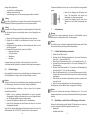
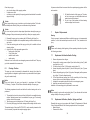
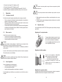
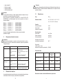
Hinweis
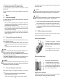
Das Nadeleinstellmaß bei PILOT WA 705 - 755 beträgt x = 91 mm und bei PILOT
WA 708 - 738 Kleber x = 98,5 mm von der Nadelspitze bis zum Mitnehmer.
6 Reinigung
6.1 Sicherheitshinweise
• Schalten Sie vor jeder Wartung die Steuer- und Zerstäuberluft sowie die
Materialzufuhr zur Spritzpistole drucklos - Verletzungsgefahr.
• Im Arbeitsbereich ist Feuer, offenes Licht und Rauchen verboten. Beim
Verspritzen leichtentzündlicher Materialien (z. B. Reinigungsmittel) besteht
erhöhte Explosions- und Brandgefahr.
• Beachten Sie die Sicherheitshinweise des Reinigungsmittel-Herstellers.
Insbesondere aggressive und ätzende Reinigungsmittel können gesundheitliche
Schäden verursachen.
6.2 Grundreinigung
Damit die Lebensdauer und die Funktion der Spritzpistole lange erhalten bleibt,
muss die Spritzpistole regelmäßig gereinigt und geschmiert werden. Verwenden Sie
zur Reinigung der Spritzpistole nur Reinigungsmittel, die vom Hersteller des
Spritzmaterials angegeben werden und die folgenden Bestandteile nicht enthalten:
• halogenierte Kohlenwasserstoffe (z. B. 1,1,1, Trichlorethan, Methylen-Chlorid
usw.)
• Säuren und säurehaltige Reinigungsmittel
• regenerierte Lösemittel (sog. Reinigungsverdünnungen)
• Entlackungsmittel.
Die o. g. Bestandteile verursachen an galvanisierten Bauteilen chemische Reaktionen
und führen zu Korrosionsschäden. Für Schäden, die aus einer derartigen Behandlung
herrühren, übernimmt WALTHER Spritz- und Lackiersysteme keine Gewährleistung.
angestrebtes Spritzergebnis
x

2120
Reinigen Sie die Spritzpistole
• vor jedem Farb- bzw. Materialwechsel
• mindestens einmal wöchentlich
• materialabhängig und je nach Verschmutzungsgrad mehrfach wöchentlich.
Achtung
Legen Sie die Spritzpistole nie in Lösemittel oder ein anderes Reinigungsmittel. Die
einwandfreie Funktion der Spritzpistole kann sonst nicht garantiert werden.
Achtung
Verwenden Sie zur Reinigung keine harten oder spitzen Gegenstände. Präzisionsteile
der Spritzpistole könnten sonst beschädigt werden und das Spritzergebnis ver-
schlechtern.
1. Zerlegen Sie die Pistole gemäß 5.6 Materialdüse und -nadel wechseln.
2. Reinigen Sie den Luftkopf und die Materialdüse mit einem Pinsel und dem
Reinigungsmittel.
3. Reinigen Sie alle übrigen Bauteile und den Pistolenkörper mit einem Tuch und
dem Reinigungsmittel.
4. Bestreichen Sie folgende Teile mit einem dünnen Fettfilm:
• Manschette des Kolbens
• O-Ring des Kolbens
• Materialnadel
• Nadelfeder
Verwenden Sie dazu ein säurefreies, nicht harzendes Fett und einen Pinsel.
Anschließend wird die Spritzpistole in umgekehrter Reihenfolge zusammengesetzt.
6.3 Routinereinigung
Bei regelmäßigen Farbwechseln oder (materialabhängig) nach Arbeitsende können
Sie die Spritzpistole auch reinigen, ohne diese dabei zerlegen zu müssen.
Hinweis
Reinigen und schmieren Sie die Spritzpistole dennoch regelmäßig gemäß Abschnitt
6.2 Grundreinigung. Sie erhalten so die sichere Funktion der Spritzpistole.
Um die Routinereinigung durchführen zu können, müssen Sie die folgenden
Arbeitsschritte durchführen:
1. Befüllen Sie den gesäuberten Materialbehälter mit einem geeigneten
Reinigungsmittel. Lediglich der Materialdruck muss an der Spritzpistole anste-
hen. Das Reinigungsmittel sollte nicht zerstäubt werden.
2. Setzen Sie die Spritzpistole in Betrieb, (siehe 5.2 Inbetriebsetzen).
3. Setzen Sie die Spritzpistole erst außer Betrieb, wenn diese nur noch klares
Reinigungsmittel verspritzt.
Damit nicht die gesamte Spritzanlage in Betrieb gesetzt werden muss, können Sie
die Materialzufuhr der PILOT WA 705 - Baureihe auch von Hand entsperren.
Die gesamte Spritzanlage sollte nun bis zum nächsten Einsatz drucklos geschaltet
werden.
7 Instandsetzung
Warnung
Schalten Sie vor jeder Instandsetzung die Steuer- und Zerstäuberluft sowie die
Materialzufuhr zur Spritzpistole drucklos - Verletzungsgefahr.
Hinweis
Zur Durchführung der im Folgenden aufgeführten Arbeitsschritte benutzen Sie bitte
die Explosionszeichnung am Anfang dieser Betriebsanleitung.
7.1 Undichte Nadelpackung austauschen
1. Schalten Sie die Pistole drucklos.
2. Schrauben Sie die 4 Befestigungsschrauben (Pos. 6) aus dem Pistolenvorder-
körper (Pos. 7) (Innensechskant SW 3).
3. Ziehen Sie den Pistolenvorderkörper (Pos. 7) vom Kolbengehäuse (Pos. 18).
4. Schrauben Sie die Packungsschraube (Pos. 15) aus dem Vorderkörper (Pos. 7)
(Schraubendreher).
5. Entfernen Sie die Packungsfeder (Pos. 14) (austauschen, falls beschädigt) und
das Druckstück (Pos. 13) aus der Einschrauböffnung.
6. Ziehen Sie die Nadelpackung (Pos. 12) mit einem Hilfswerkzeug aus ihrem Sitz.
Verwenden Sie hierzu einen festen Draht, dessen Ende zu einem kleinen Haken
umgebogen ist.
7. Fetten Sie die neu einzusetzende Nadelpackung mit einem säurefreien, nicht
harzenden Fett ein.
8. Setzen Sie die neue Nadelpackung in den Pistolenvorderkörper ein.
Die Montage der restlichen Bauteile erfolgt in umgekehrter Reihenfolge.
Hinweis
Die aus dem Pistolenvorsatz entnommene Nadelpackung (Pos. 12) darf nicht
wiederverwendet werden, da sonst eine funktionssichere Dichtwirkung nicht gewähr-
leistet ist.
7.2 Materialdüse, -nadel, Federn und Dichtungen austauschen
Zerlegen Sie die Spritzpistole gemäß Abschnitt 5.6 Materialdüse und -nadel wech-
seln, wenn die folgenden Bauteile ausgetauscht werden müssen:
• Materialdüse
• Druckfeder des Kolbens
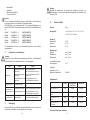
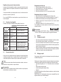
1. Ziehen Sie die Zugstange der Spritzpistole nach
hinten. Die Materialzufuhr wird geöffnet und
Materialkanal und -düse werden gereinigt.
2. Lassen Sie die Zugstange erst los, wenn an der
Spritzpistole nur noch klares Reinigungsmittel aus-
tritt.

2322
• Materialnadel*
• Nadelfeder*
• Manschette des Kolbens*
• O-Ring des Kolbens*
Hinweis
Die mit * gekennzeichneten Bauteile müssen vor dem Einbau in den Pistolenkörper
mit einem säurefreien, nicht harzenden Fett eingefettet werden.
WALTHER Spritz- und Lackiersysteme hält für die Automatik-Spritzpistolen der
Baureihe PILOT WA 705 Reparatursets bereit, die sämtliche Verschleißteile enthal-
ten:
Art. Nr.: V 16 207 05 . . 3 (WA 705 / WA 715)
Art. Nr.: V 16 207 25 . . 3 (WA 725 / WA 735)
Art. Nr.: V 16 207 45 . . 3 (WA 745 / WA 755)
Art. Nr.: V 16 207 08 . . 3 (WA 708 / WA 718)
Art. Nr.: V 16 207 28 . . 3 (WA 728 / WA 738)
Die Verschleißteile sind auch in der Ersatzteilliste aufgeführt (durch Fettdruck
gekennzeichnet).
8 Fehlersuche und -beseitigung
Warnung
Schalten Sie vor jeder Wartung und Instandsetzung die Steuer- und Zerstäuberluft
sowie Materialzufuhr zur Spritzpistole drucklos - Verletzungsgefahr.
Fehler Ursache Abhilfe
Pistole tropft
Materialnadel oder -düse
verschmutzt
Materialnadel oder -düse
beschädigt
Packungsschraube zu fest
angezogen
siehe 5.6 Materialnadel
oder -düse ausbauen und reinigen
siehe 7.2 Materialnadel oder -düse
austauschen
Packungsschraube (Pos. 15)
mit Schraubendreher etwas lösen
Pistole öffnet nicht Steuerluft zu niedrig
Steuerluftdruck erhöhen auf min. 4,5
bar
Material tritt an der
Leckagebohrung aus
Nadelpackung ist undicht
Packungsschraube ist lose
siehe 7.1 Nadelpackung austauschen
Packungsschraube (Pos. 15) mit
Schraubendreher etwas anziehen
Stoßweiser oder flat-
ternder Spritzstahl
zu wenig Material im
Materialbehälter
Material auffüllen (siehe Betriebs-
anleitung des Anlagenherstellers)
9 Entsorgung
Die bei der Reinigung und Wartung anfallenden Materialien sind den Gesetzen und
Vorschriften entsprechend sach- und fachgerecht zu entsorgen.
Warnung
Beachten Sie insbesondere die Hinweise des Herstellers der Spritz- und
Reinigungsmittel. Unachtsam entsorgtes Material gefährdet die Gesundheit von
Mensch und Tier.
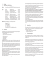
10 Technische Daten
Gewicht: 623 g
Düsengrößen: ▪ 0,3 ▪ 0,5 ▪ 0,8 ▪ 1,0 ▪ 1,2 ▪ 1,5 ▪ 1,8 ▪ 2,0
▪ 2,2 ▪ 2,5 ▪ 3,0 ▪ 3,5 mm ø
Anschluss:
Zerstäuberluft G 1/8“
Steuerluft G 1/8“
Materialzufuhr G 1/4“
Druckbereiche:
Steuerluft mind. 4,5 bar
Materialdruck max. 8 bar
Zerstäuberluft max. 8 bar
max. Betriebstemperatur
der Spritzpistole 80 °C
Schallpegel
(gemessen in ca. 1 m
Abstand zur Spritzpistole) 86 dB (A)
Luftverbrauch:
Luftkopf Eingangsluftdruck
an der Pistole
Luftverbrauch
PILOT WA 705 / 715 1031 4,0 bar 360 L/min.
PILOT WA 725 / 735
HVLP
1061 3,5 bar 340 L/min.
PILOT WA 745 / 755
HVLP
PLUS
1060 3,4 bar 290 L/min.
PILOT WA 728 / 738
HVLP Kleber
1055 K 3,4 bar 310 L/min
Technische Änderungen vorbehalten.

2524
Contents
Exploded Drawing 2
Declaration of CE-Conformity 25
Replacement parts 26
1 General 30
1.1 Identification of Model Version 30
1.2 Normal Use 30
1.3 Improper Use 31
2 Technical Description 31
3 Safety Warnings 32
3.1 Safety Warting Symbols 32
3.2 Generally Applicable Safety Precautions 32
4 Assembly / Installation 33
4.1 Mounting of Spray Gun 33
4.2 Connection of Input Lines 33
5 Operational Handling 34
5.1 Safety Warnings 34
5.2 Starting/Stopping Requirements 34
5.3 Spray Pattern Test 34
5.4 Spray Pattern Adjustments 35
5.5 Correcting of Spray Pattern Imperfections 36
5.6 Retooling of Spray Gun 36
6 Cleaning 37
6.1 Safety Warnings 37
6.2 Cleaning - Complete 37
6.3 Cleaning - Routine 38
7 Repairs / Replacements 39
7.1 Replacement of defective Needle Seal Packings 39
7.2 Replacement of Nozzles, Needles, Springs 39
and Seals
8 Trouble shooting and Corrective Action 40
9 Disposal of Cleaning / Servicing Substances 40
10 Specification Data 41
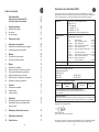
EC/EU Declaration ofConformity
We, the manufacturers of the equipment, hereby declare under our sole responsibility that the product(s)
described below conform to the essential safety requirements. This declaration will be rendered invalid if any
changes are made to the equipment without prior consultation with us.
Manufacturer WALTHER Spritz- und Lackiersysteme GmbH
Kärntner Str. 18 - 30
D - 42327 Wuppertal
Tel.: +49(0)202 / 787 - 0
Fax: +49(0)202 / 787 - 2217
www.walther-pilot.de • e-mail: [email protected]
Type Designation
Automatic Spray Gun
PILOT WA 705-Serie without internal control
WA 705 (Standard) V 20 705
WA 715-U (Standard-circulation) V 20 715
WA 725-HVLP (Low pressure) V 20 725
WA 735-HVLP-U (Low pres.-circulation) V 20 735
WA 745-HVLP
PLUS
(Medium pressure) V 20 745
WA 755-HVLP
PLUS
-U (Medium pres.-circulation) V 20 755
WA 708-K (Standard-adhesive version) V 20 708
WA 718-U-K (Standard-adhesive vers.-circul.) V 20 718
WA 728-HVLP-K (Low pressure-adhesive version) V 20 728
WA 738-HVLP-U-K (Low pressure-adhesive vers.-circul.) V 20 738
Intended purpose Processing of sprayable media
Applied Standards and Directives
EU-Mechanical Engineering Directives 2006/42/EC
2014/34/EU (ATEX Directives)
DIN EN ISO 12100
DIN EN 1953 DIN EN 13463-1
DIN EN 1127-1 DIN EN 13463-5
Specification according 2014/34/EU
Category 2 Part marking
II 2 G c T 5
Tech.File,Ref.:
2414
Authorized with the compilation of the technical file:
Nico Kowalski, WALTHER Spritz- und Lackiersysteme GmbH, Kärntner Str. 18 - 30
D- 42327 Wuppertal
Special remarks :
The named product is intended for installation in other equipment. Commissioning is prohibited until such
time as the end product has been proved to conform to the provision of the Directives 2006/42/EC.
Wuppertal, the 2nd of November 2016
Name: Torsten Bröker
Position: Manager, Design and Development
This Declaration does not give assurance of properties in the sense of product liability. The safety instructions
provided in the product documentation must be observed at all times.
p.p.

2726
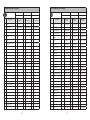
Listing of Replacement Parts:
WA 705 WA 715-U WA 725-HVLP
V 20 705 V 20 715 V 20 725
Item
Description
piece
Parts No.
piece
Parts No.
piece
Parts No.
1 Retaining Ring compl. 1 V 20 700 05 000 1 V 20 700 05 000 1 V 20 700 05 000
2 Air Cap* 1 V 10 700 35 XX8* 1 V 10 700 35 XX8* 1
V 10 700 37 XXX*
3 Material nozzle* 1 V 10 700 40 XX3* 1 V 10 700 40 XX3* 1 V 10 700 40 XX3*
5 Sealing Washer 1 V 20 700 04 000 1 V 20 700 04 000 1 V 20 700 04 100
6 Hexagon socket screw 4 V 20 700 13 003 4 V 20 700 13 003 4 V 20 700 13 003
7 Front Body compl. 1 V 20 700 03 000 1 V 20 710 03 000 1 V 20 700 03 000
8 Pin to fix air cap 1 V 20 700 02 303 1 V 20 700 02 303 1 V 20 700 02 303
9 Locking spring 1 V 20 700 02 403 1 V 20 700 02 403 1 V 20 700 02 403
10 Set screw 1 V 20 310 01 503 1 V 20 310 01 503 1 V 20 310 01 503
11 O-Ring 2 V 09 103 64 009 2 V 09 103 64 009 2 V 09 103 64 009
12 Needle seal Packing com. 1 V 09 001 72 000 1 V 09 001 72 000 1 V 09 001 72 000
13 Pressure peace 1 V 10 361 07 000 1 V 10 361 07 000 1 V 10 361 07 000
14 Packing Spring 1 V 20 510 12 003 1 V 20 510 12 003 1 V 20 510 12 003
15 Packing Screw 1 V 20 510 11 003 1 V 20 510 11 003 1 V 20 510 11 003
16 Packing Screw 1 V 22 650 43 100 1 V 22 650 43 100 1 V 22 650 43 100
17 Lip seal 1 V 09 220 30 000 1 V 09 220 30 000 1 V 09 220 30 000
18 Piston Casing compl. 1 V 20 705 01 000 1 V 20 705 01 000 1 V 20 705 01 000
19 Seal pack 1 V 20 700 07 000 1 V 20 700 07 000 1 V 20 700 07 000
20 Piston 1 V 20 705 08 000 1 V 20 705 08 000 1 V 20 705 08 000
21 Piston Spring 1 V 20 606 11 000 1 V 20 606 11 000 1 V 20 606 11 000
22 Threaded Ring compl. 1 V 20 700 09 000 1 V 20 700 09 000 1 V 20 700 09 000
23 Material Needle compl.* 1 V 20 705 30 XX3* 1 V 20 705 30 XX3* 1 V 20 705 30 XX3*
24 Needle Spring 1 V 20 510 29 003 1 V 20 510 29 003 1 V 20 510 29 003
25 Cap compl. 1 V 20 700 10 000 1 V 20 700 10 000 1 V 20 700 10 000
26 Drawbar compl. 1 V 20 510 34 000 1 V 20 510 34 000 1 V 20 510 34 000
27 Push-in-fitting 2 V 66 101 53 015 2 V 66 101 53 015 2 V 66 101 53 015
28 Push-in-fitting 1 V 66 101 53 013 1 V 66 101 53 013 1 V 66 101 53 013
29 Barrel Nipple G1/4 1 V 00 101 01 003 2 V 00 101 01 003 1 V 00 101 01 003
30 Blanking plug 1 V 20 540 40 003 not applicable 1 V 20 540 40 003
Listing of Replacement Parts:
WA 735-HVLP-U WA 745-HVLP
PLUS
WA 755-HVLP
PLUS
-U
V 20 735 V 20 745 V 20 755
Item
Description
piece
Parts No.
piece
Parts No.
piece
Parts No.
1 Retaining Ring compl. 1 V 20 700 05 000 1 V 20 700 05 000 1 V 20 700 05 000
2 Air Cap* 1
V 10 700 37 XXX*
1
V 10 700 36 XXX*
1
V 10 700 36 XXX*
3 Material nozzle * 1 V 10 700 40 XX3* 1 V 10 700 40 XX3* 1 V 10 700 40 XX3*
5 Sealing Washer 1 V 20 700 04 100 1 V 20 700 04 100 1 V 20 700 04 100
6 Hexagon socket screw 4 V 20 700 13 003 4 V 20 700 13 003 4 V 20 700 13 003
7 Front Body compl. 1 V 20 710 03 000 1 V 20 700 03 000 1 V 20 710 03 000
8 Pin to fix air cap 1 V 20 700 02 303 1 V 20 700 02 303 1 V 20 700 02 303
9 Locking spring 1 V 20 700 02 403 1 V 20 700 02 403 1 V 20 700 02 403
10 Set screw 1 V 20 310 01 503 1 V 20 310 01 503 1 V 20 310 01 503
11 O-Ring 2 V 09 103 64 009 2 V 09 103 64 009 2 V 09 103 64 009
12 Needle seal Packing com. 1 V 09 001 72 000 1 V 09 001 72 000 1 V 09 001 72 000
13 Pressure peace 1 V 10 361 07 000 1 V 10 361 07 000 1 V 10 361 07 000
14 Packing Spring 1 V 20 510 12 003 1 V 20 510 12 003 1 V 20 510 12 003
15 Packing Screw 1 V 20 510 11 003 1 V 20 510 11 003 1 V 20 510 11 003
16 Packing Screw 1 V 22 650 43 100 1 V 22 650 43 100 1 V 22 650 43 100
17 Lip seal 1 V 09 220 30 000 1 V 09 220 30 000 1 V 09 220 30 000
18 Piston Casing compl. 1 V 20 705 01 000 1 V 20 705 01 000 1 V 20 705 01 000
19 Seal pack 1 V 20 700 07 000 1 V 20 700 07 000 1 V 20 700 07 000
20 Piston 1 V 20 705 08 000 1 V 20 705 08 000 1 V 20 705 08 000
21 Piston Spring 1 V 20 606 11 000 1 V 20 606 11 000 1 V 20 606 11 000
22 Threaded Ring compl. 1 V 20 700 09 000 1 V 20 700 09 000 1 V 20 700 09 000
23 Material Needle compl.* 1 V 20 705 30 XX3* 1 V 20 705 30 XX3* 1 V 20 705 30 XX3*
24 Needle Spring 1 V 20 510 29 003 1 V 20 510 29 003 1 V 20 510 29 003
25 Cap compl. 1 V 20 700 10 000 1 V 20 700 10 000 1 V 20 700 10 000
26 Drawbar compl. 1 V 20 510 34 000 1 V 20 510 34 000 1 V 20 510 34 000
27 Push-in-fitting 2 V 66 101 53 015 2 V 66 101 53 015 2 V 66 101 53 015
28 Push-in-fitting 1 V 66 101 53 013 1 V 66 101 53 013 1 V 66 101 53 013
29 Barrel Nipple G1/4 2 V 00 101 01 003 1 V 00 101 01 003 2 V 00 101 01 003
30 Blanking plug not applicable 1 V 20 540 40 003 not applicable

2928
Listing of Replacement Parts:
WA 708-adhesive WA 718-U-
adhesive
WA 728-HVLP-
adhesive
WA 738-HVLP-U-
adhesive
V 20 708 V 20 718 V 20 728 V 20 738
Item
Description
piece
Parts No.
piece
Parts No.
piece
Parts No.
piece
Parts No.
1
Retaining Ring compl.
1 V 20 700 05 000 1 V 20 700 05 000 1 V 20 700 05 000 1 V 20 700 05 000
2
Air Cap*
1 V 10 711 35 XX5* 1 V 10 711 35 XX5* 1 V 10 711 35 XX5* 1 V 10 711 35 XX5*
3
Material nozzle*
1 V 10 711 40 XX3* 1 V 10 711 40 XX3* 1 V 10 711 40 XX3* 1 V 10 711 40 XX3*
5
Sealing Washer
1 V 20 700 04 000 1 V 20 700 04 000 1 V 20 700 04 100 1 V 20 700 04 100
6
Hexagon socket screw
4 V 20 700 13 003 4 V 20 700 13 003 4 V 20 700 13 003 4 V 20 700 13 003
7
Front Body compl.
1 V 20 700 03 000 1 V 20 710 03 000 1 V 20 700 03 000 1 V 20 710 03 000
8
Pin to fix air cap
1 V 20 700 02 303 1 V 20 700 02 303 1 V 20 700 02 303 1 V 20 700 02 303
9
Locking spring
1 V 20 700 02 403 1 V 20 700 02 403 1 V 20 700 02 403 1 V 20 700 02 403
10
Set screw
1 V 20 310 01 503 1 V 20 310 01 503 1 V 20 310 01 503 1 V 20 310 01 503
11
O-Ring
2 V 09 103 64 009 2 V 09 103 64 009 2 V 09 103 64 009 2 V 09 103 64 009
12 Needle seal Packing com. 1 V 09 001 72 000 1 V 09 001 72 000 1 V 09 001 72 000 1 V 09 001 72 000
13
Pressure peace
1 V 10 361 07 000 1 V 10 361 07 000 1 V 10 361 07 000 1 V 10 361 07 000
14
Packing Spring
1 V 20 510 12 003 1 V 20 510 12 003 1 V 20 510 12 003 1 V 20 510 12 003
15
Packing Screw
1 V 20 510 11 003 1 V 20 510 11 003 1 V 20 510 11 003 1 V 20 510 11 003
16
Packing Screw
1 V 22 650 43 100 1 V 22 650 43 100 1 V 22 650 43 100 1 V 22 650 43 100
17
Lip seal
1 V 09 220 30 000 1 V 09 220 30 000 1 V 09 220 30 000 1 V 09 220 30 000
18
Piston Casing compl.
1 V 20 705 01 000 1 V 20 705 01 000 1 V 20 705 01 000 1 V 20 705 01 000
19
Seal pack
1 V 20 700 07 000 1 V 20 700 07 000 1 V 20 700 07 000 1 V 20 700 07 000
20
Piston
1 V 20 705 08 000 1 V 20 705 08 000 1 V 20 705 08 000 1 V 20 705 08 000
21
Piston Spring
1 V 20 606 11 000 1 V 20 606 11 000 1 V 20 606 11 000 1 V 20 606 11 000
22
Threaded Ring compl.
1 V 20 700 09 000 1 V 20 700 09 000 1 V 20 700 09 000 1 V 20 700 09 000
23
Material Needle compl.*
1 V 20 728 30 XX3* 1 V 20 728 30 XX3* 1 V 20 728 30 XX3* 1 V 20 728 30 XX3*
24
Needle Spring
1 V 20 510 29 003 1 V 20 510 29 003 1 V 20 510 29 003 1 V 20 510 29 003
25
Cap compl.
1 V 20 700 10 000 1 V 20 700 10 000 1 V 20 700 10 000 1 V 20 700 10 000
26
Drawbar compl.
1 V 20 510 34 000 1 V 20 510 34 000 1 V 20 510 34 000 1 V 20 510 34 000
27
Push-in-fitting
2 V 66 101 53 015 2 V 66 101 53 015 2 V 66 101 53 015 2 V 66 101 53 015
28
Push-in-fitting
1 V 66 101 53 013 1 V 66 101 53 013 1 V 66 101 53 013 1 V 66 101 53 013
29
Barrel Nipple G1/4
1 V 00 101 01 003 2 V 00 101 01 003 1 V 00 101 01 003 2 V 00 101 01 003
30
Blanking plug
1 V 20 540 40 003
not applicable
1 V 20 540 40 003
not applicable
* Please quote the required size(s) when placing an order for replacement parts.
It is recommended to keep in stock all BOLD-faced parts (fast wearing parts).
Repair kit
WALTHER PILOT repair kits are available for PILOT WA 705 - WA 755 HVLP
PLUS
-U and the
corresponding versions of adhesive coating PILOT WA 708-K - WA 738 HVLP-U-K spray
guns including all wearing parts.
Parts No.
PILOT WA 705/ 715 Standard-version V 16 207 05 XX3
PILOT WA 725 / 735 HVLP / Low pressure-version V 16 207 25 XX3
PILOT WA 745 / 755 HVLP
PLUS
/ Mediem pressure-version V 16 207 45 XX3
PILOT WA 708 / 718 Standard-adhesive version V 16 207 08 XX3
PILOT WA 728 / 738 HVLP / Low pressure-adhesive
version
V 16 207 28 XX3
Nozzle set
Nozzle sets consist of air cap, material nozzle and material needle.
Parts No.
PILOT WA 705 / 715 Standard-version V 15 207 05 XX3
PILOT WA 725 / 735 HVLP / Low pressure-version V 15 207 25 XX3
PILOT WA 745 / 755 HVLP
PLUS
/ Mediem pressure-version V 15 207 45 XX3
PILOT WA 708 / 718 Standard-adhesive version V 15 207 08 XX3
PILOT WA 728 / 738 HVLP / Low pressure-adhesive
version
V 15 207 28 XX3
Nozzle sizes optional:
▪ 0,3 ▪ 0,5 ▪ 0,8 ▪ 1,0 ▪ 1,2 ▪ 1,5 ▪ 1,8 ▪ 2,0 ▪ 2,2 ▪ 2,5 ▪ 3,0 ▪ 3,5 mm ø

3130
1 General
1.1 Identification of Model Version
Models: Automatic Spray Guns PILOT WA 705 - Serie without internal control
Types: WA 705 (Standard-version) V 20 705
WA 715-U (Standard-circulation-version) V 20 715
WA 725-HVLP (Low pressure-version) V 20 725
WA 735-HVLP-U (Low pres.-circulation-version) V 20 735
WA 745-HVLP
PLUS
(Mediem pressure-version) V 20 745
WA 755-HVLP
PLUS
-U (Medium pres.-circulation-version) V 20 755
WA 708-K (Standard-adhesive version) V 20 708
WA 718-U-K (Standard-circulation-adhesive-vers.) V 20 718
WA 728-HVLP-K (Low pressure-adhesive version) V 20 728
WA 738-HVLP-U-K (Low pres.-adhesive-circulation vers.) V 20 738
Manufacturer: WALTHER Spritz- und Lackiersysteme GmbH
Kärntner Str. 18-30
D-42327 Wuppertal
Tel.: 0202 / 787-0
Fax: 0202 / 787-2217
www.walther-pilot.de • Email:info@walther-pilot.de
1.2 Normal Use
The automatic spray guns of the series PILOT WA 705 are exclusively designed for
use with sprayable material types and grades such as:
• paints and lacquers
• greases, oils and corrosion preventives
• adhesive compounds
• Separating agent
• ceramic glazes
• pickling solutions
Should the materials which you want to spray not be listed above, please contact
WALTHER Spritz- und Lackiersysteme, Wuppertal for further and detailed informati-
on.
Please note that sprayable material may only be applied to work pieces and/or simi-
lar items. The temperature of the spraying materials shall never exceed 80 degrees
Celsius. The models of the series PILOT WA 7XX are not designed for manual ope-
ration, and must be installed in a suitable gun mounting device.
The term normal use also implies that any and all safety warnings, operational hand-
ling details, etc., as stated in these operating instructions, must be carefully read,
understood and duly complied with.
This equipment complies with the explosion protection requirements of Directive
2014/34/EU (ATEX) for the explosion group, equipment category and temperature
class indicated on the type plate.
When using the equipment, the requirements specified in these Operating Instructions
must be observed at all times.
The technical data indicated on the equipment rating plates and the specifications in
the chapter "Technical Data" must be complied with at all times and must not be
exceeded. An overloading of the equipment must be ruled out.
The equipment may be used in potentially explosive atmospheres only with the
authorisation of the relevant supervisory authority.
The relevant supervisory authority or the operator of the equipment are
responsible for determining the explosion hazard (zone classification).
The operator must check and ensure that all technical data and the marking of the
equipment in accordance with ATEX are compliant with the necessary requirements.
The operator must provide corresponding safety measures for all applications in
which the breakdown of the equipment might lead to danger to persons.
If any irregularities are observed while the equipment is in operation, the equipment
must be put out of operation immediately and WALTHER Spritz- und Lackiersysteme
must be consulted.
Grounding / Equipotential Bonding
You must ensure that the spray gun is properly earthed (grounded) either separately
or in connection with the equipment with which it is being used (maximum resistance
10
6
Ω).
1.3 Improper Use
This spray gun shall not be used for purposes other than set forth in the above
Chapter 1.2 Normal Use. Any other form of use and/or application is prohibited.
Improper use is for example:
• spraying of material onto persons and animals
• spraying of liquid nitrogen, etc.
2 Technical Description
The models PILOT WA 705 are an all-automatic air-controlled guns operating in
combination with a 3/2-way control valve in the form of hand-, foot- or solenoid
actuated valves.
At first the atomizing air (round- and wide/flat jet air item 27) is openened by a 3/2-
way control valve. Then activate the control air that push back the piston and the
material needle to open the material supply.
For the models PILOT WA 7XX the spray jet contour (flat/wide/round) is adjusted by
a pressure regulator in the plant.
Closing of the 3/2-way valve is followed by the control air escaping from the cylinder
inside the gun, upon which the spring-loaded material needle returns to its initial
position, where it shuts the material and atomizing air input off.
The material flow volume is set with all models via the material pressure and by
limiting the orifice travel of the material needle on the cap (item 25).
The material flow of the automatic spray gun series PILOT WA 7XX can also be
opened by hand using the pulling rod (item 26) to clean, for example, a clogged
material nozzle. The spray guns of the PILOT WA 7XX series can be connected to
material pressure tanks and pumping systems.

3332
The models PILOT WA 715-U / WA 735-HVLP-U / WA 755-HVLP
PLUS
-U /WA 718-U-K
and WA 738-HVLP-U-K with connection for paint circulation can be integrated into a
system with circulation.
The models PILOT WA 725-HVLP / WA 735 HVLP-U / WA 728 HVLP-K and
WA 738 HVLP-U-K are pure low-pressure spray guns working with a spraying air
pressure of 0.7 bar at an intake air pressure of 4.5 bar.
With the models PILOT WA 745-HVLP
PLUS
and WA 755 HVLP
PLUS
-U the intake air pres-
sure ranges from 3.0 to 3.3 bar for a spraying air pressure from 1.2 to 1.4 bar.
3 Safety Warnings
3.1 Safety Warning Symbols
Warning
This pictograph and the accompanying warning note „Warning“ indicate possible
risks and dangers for yourself. - Possible consequences: Injuries of any kind.
Caution
This pictograph and the accompanying warning note „Caution“ indicate possible
damage to equipment. - Possible consequences: Damage to equipment, workpi-
eces, etc.
Notice
This pictograph and the accompanying note „Notice“ indicate additional and useful
information to help you handling the spray gun with even greater confidence and
efficiency.
3.2 Generally Applicable Safety Precautions
► All applicable accident prevention rules and regulations as well as other recog-
nised industrial safety and health rules and regulations must be observed at all
times.
► Use the spray gun only in well-ventilated rooms. Fire, naked flames and smoking
are strictly prohibited within the working area. WARNING – during the spraying
of flammable materials (e.g. lacquers, adhesives, cleaning agents, etc.), there is
an increased risk to health as well as an increased risk of explosion and fire.
► You must ensure that the spray gun is properly earthed (grounded) either sepa-
rately or in connection with the equipment with which it is being used
(max. resistance 10
6
Ω).
► Before carrying out maintenance or servicing work, always ensure that the air
and material feed to the spray gun have been de-pressurised. Risk of injury!
► When spraying materials, do not place your hands or other parts of the body
infront of the pressurised nozzle or the spray gun. - Risk of injury!
► Never point the spray gun at persons or animals. - Risk of injury!
► Always observe the spraying and safety instructions given by the manufacturers
of the spraying material and the cleaning agent. Aggressive and corrosive mate-
rials in particular can be harmful to health.
► Always wear hearing protection when using the gun or when in the vicinity of a
gun that is in use. The noise level generated by the spray gun is approx.
86 dB(A).
► Exhaust air containing particles (overspray) must be kept away from the working
area and personnel. In spite of these measures, always wear the regulation
breathing masks and protective overalls when using the gun. Airborne particles
represent a serious health hazard!
► After carrying out assembly or maintenance work, always ensure that all nuts,
bolts and screw connections have been fully tightened before the gun is used.
► Use only original replacement parts, since WALTHER can only guarantee safe
and fault-free operation for original parts.
► For further information on the safe use of the spray gun and the spraying mate-
rials, please contact WALTHER Spritz- und Lackiersysteme GmbH,
D-42327 Wuppertal, Germany.
4 Assembly / Installation
This spray gun is delivered in completely assembled condition. Before taking the
spray gun into operation perform the following preparations:
4.1 Mounting of Spray Gun
Install the gun in a suitable and stable mounting device as shown in the following
example:
4.2 Connection of Input Lines
Warning
Make sure not to confuse the control and atomizing air connections -risk of injury.
1 = Material inlet fitting (G 1/4“)
2 = Control air inlet fitting (G 1/8“) marked with ST
Use the two through holes here with a
dia. of 5.3 mm (1) with a hole spacing
of 28 mm and the two threaded holes
M5 with a hole spacing of 28 mm (2).
Other mounting devices upon request.
(2) (1)
5
5
3
2
1
4

3534
3 = Wide spray air connection (G 1/8”) marked with B
4 = Round spray air connection (G 1/8”) marked with R
5 = Material inlet fitting for the circulation versions of the PILOT WA 7XX models
The spray gun is now properly installed and connected and ready for operation.
5 Operational Handling
5.1 Safety Warnings
Please pay special attention to the following safety warnings prior to taking this spray
gun into operation!
• Wear proper respiratory protection masks and protective overalls, whenever you
are operating this spray gun. Air-borne particles represent a health hazard.
• Make sure to wear suitable hearing protectors. The gun produces sound levels
of up to 86 dB (A) which may cause hearing defects.
• Open fires, naked lights and smoking prohibited in the working area. Spraying
of readily flammable media such as paints and adhesive compounds is always
accompanied by the risk of fire and explosion.
5.2 Starting / Stopping Requirements
The following requirements must be met before taking this spray gun into operation:
• control air must be available at the gun.
• atomizing air must be available at the gun.
• material pressure must be available at the gun.
Caution
The material pressure shall not exceed • 8 bar, as, otherwise, the functional reliabty
of the spray gun will suffer.
Adjust the control air pressure to • at least 4,5 bar, in order to operate the spray gun.
The operation of the spray gun can be started/stopped by way of the 3/2-way control
valve (see the Operating Instructions of the plant systems manufacturer).
Warning
It is important to remember that the spray gun must be relieved of all pressures
whenever work is terminated. Lines left in pressurized condition could burst, with
their contents likely to injure anybody present nearby.
5.3 Spray Pattern Test
Spray pattern tests should be performed whenever:
• the spray gun is taken into operation for the first time.
• the spraying medium is changed.
• the spray gun was taken apart for servicing or repairs.
The spray pattern can be tested using a work piece sample, a sheet of metal,
cardboard or paper.
Warning
Keep away from the front of the spray gun - imminent risk of injury.
Warning
Make sure that nobody is present in the spraying zone when the gun is started
- imminent Risk of Injury.
1. Start the gun to produce a spray pattern sample (see 5.2. Starting/Stopping
Requirements).
2. Inspect the sample and readjust the settings of the gun as may be required (see
5.4 Spray Pattern Adjustments).
5.4 Spray Pattern Adjustments
The spray pattern of the of the series PILOT WA 705 models can be adjusted as
follows:
Adjusting the jet pattern
Adjustment of the material flow rate
Adjustment of the Material Pressure
This adjustment can only be made at the pump or the material pressure tank. Please
comply with the operating instructions and safety warnings issued by the manufac-
turers concerned.
The spray pattern is adjusted by a pressure regu-
lator in the plant (see operating instructions of
plant systems manufacturer).
The connection B is for the wide jet, the connec-
tion R is for the round jet.
Turn cap (1) from the standard position.
• to the inside in order to decrease the material
flow rate.
• to the outside in order to increase the material
flow rate.
The material flow through the nozzle can be perfor-
med without using atomizing air, when the drawbar
(2).
2
1
B
R

3736
Adjustment of the Atomizing Air Pressure
The atomizing air pressure is adjusted at the air pressure reducing valve of the com-
pressor system. Please comply with the operating instructions and safety warnings
issued by the manufacturer.
If you wish to change the spraying pattern beyond the adjustments outlined so far,
you must retool the spray gun (See 5.6 Retooling of Spray Gun).
WALTHER offers a great variety of air cap/-material nozzle/needle combinations for
this purpose.
5.5 Correcting of Spray Pattern Imperfections
The following table shows what to do to correct a spray pattern.
Spray pattern test Fault Required adjustment
Spray pattern is split in the
centre
• setting a wider spray pattern
Spray pattern is too thick at
the ends
• Setting a more rounded spray
pattern
The spray pattern shows
rather large droplets
• Increase the nozzle air pressure
Material application in the
centre of the spray pattern is
very thin
• Decrease the nozzle air pressure
Spray pattern is split in
the centre
• Increase the nozzle diameter
• Reduce nozzle air pressure
• Increase material pressure
Spray pattern is very spheri-
cal
• Reduce material pressure
• Increase nozzle air pressure
5.6 Retooling of Spray Gun
Combinations of air cap, material nozzle and needle, designed to match specific
spraying media types and grades, form a unit - namely the nozzle insert assembly.
In order maintain the desired spray-finish quality standard always replace the com-
plete nozzle insert assembly.
Warning
Prior to retooling: Make sure that the spray gun is in unpressurized condition, i.e. all
air and material inputs must be shut off - if not, imminent risk of injury.
Notice
In order to perform the following procedures please use the drawing at the beginning
of these operating instructions.
Replacement of Air Cap
1. Unscrew the knurled air cap retaining ring in (item 1) from the front body (Item 7).
2. Pull the air cap (item 2) of the front body.
3. Position the required air cap on the front.
4. Screw the air cap retaining ring in (item 1) onto the front.
Replacement of Material Control Nozzle and Needle
1. Remove the air control head (item 2) (see 5.6 Replacement of Air Control Head).
2. Unscrew the material nozzle in (item 3) from the front (item 7) (width over flats
of hex. nut 13).
3. Pull out the pulling rod (item 26) together with the material needle (item 23).
4. Unscrew the cap in (item 25) from the threaded ring in (item 22) and remove the
needle spring (item 24).
5. Pull the material needle (item 23) out of the piston housing (item 18).
Installation of the new nozzle insert assembly and the remaining parts is performed
in the reverse order.
Notice
The needle setting for the PILOT WA 705 - 755 is x = 91 mm and for the PILOT
WA 708 - 738 adhesive x = 98,5 mm from the needle tip to the driving tenon.
6 Cleaning
6.1 Safety Warnings
• Prior to any servicing and repair work: Make sure that the spray gun is in unpres-
surized condition, i.e. all air and material inputs must be shut off - if not, immi-
nent risk of injury.
• No open fires, naked light and smoking allowed in the work area. When spraying
readily flammable media such as cleaning solutions, there is an increased risk
of fire and explosion.
• Observe the safety warnings issued by the manufacturer. Aggressive and corro-
sive media represents risks and hazards to personal health.
6.2 Cleaning - Complete
Regular cleaning and lubrication of the spray gun has to be performed, in order to
increase the service life and the function of the spray gun.
Clean the gun only with cleaning solutions recommended by the manufacturer of the
spraying material used at the time. It is important to make sure that cleaning soluti-
ons do not contain any of the following constituents:
• halogenated hydrocarbons (e.g. 1,1,1-trichloroethane, methylene chloride, etc.)
• acids and acidiferous cleaning solutions
• regenerated solvents (so-called cleaning dilutions)
• paint removers.
The above constituents cause chemical reactions with the electroplated components
resulting in corrosion damage. WALTHER Spritz- und Lackiersysteme is not respon-
sible for any damages resulting from such treatment.
desired spray result
x

3938
Clean the spray gun
• prior to each change of the spraying medium.
• at least once a week.
• as often as may be required by the spraying medium handled and the resultant
degree of fouling.
Caution
Never immerse the spray gun in solvent or any other cleaning solution. The functio-
nal reliability and efficiency of the gun can otherwise not be guaranteed.
Caution
Do not use any hard, pointed or sharp-edged objects when cleaning the spray gun.
Any damage of the precision-made parts are likely to affect your spraying results.
1. Dismantle the spray gun in accordance with 5.6 Retooling the Spray Gun.
2. Use a soft brush together with a compatible cleaning sulotion to clean the air cap
and nozzle.
3. Clean the remaining parts and the spray gun body with a suitable cloth and
cleaning solution.
4. Apply a thin film of the appropriate grease to the:
• sealing collar of the piston
• O-ring of the piston
• material control needle
• needle spring
Make sure to use a non-acidic, non-resinogenic grease and a soft brush. The spray
gun is then reassembled in reverse order.
6.3 Cleaning - Routine
The spray gun need not necessarily be dismantled for cleaning if and when the
spraying medium is changed in regular intervals or upon termination of work (depen-
ding on the material used).
Notice
Clean and lubricate the spray gun frequently in accordance with Chapter
6.2 Cleaning - Complete. This will ensure functional reliability of the spray gun.
The following requirements must be met before the routine cleaning work can be
performed:
1. The material tank must be clean and then be filled with a compatible cleaning
solution. Material pressure has to be available at the spray gun. The cleaning
solution should not be sprayed.
2. Take the spray gun into operation (see 5.2 Starting the Spray Gun).
3. Do not stop the spray gun until clear cleaning solution emerges from the nozzle.
The material supply of the series PILOT WA 7XX can be manually released so that
it is not necessary to operate the complete spraying system.
All pressures should then be removed from the complete spraying system until the
next operation.
7 Repairs / Replacements
Warning
Prior to any repairs / replacements: Make sure that the spray gun is in unpressurized
condition, i.e. all air and material inputs must be shut off - if not, imminent risk of
injury.
Notice
Please use the drawing at the beginning of these operating instructions to perform
the following procedures.
7.1 Replacement of defective Needle Packing
1. Remove all pressures from the gun.
2. Unscrew the 4 mounting screws in (item 6) from the front body in (item 7) (width
over flats of hex. nut 3).
3. Pull the front body in (item 7) off the piston casing in (item 18).
4. Unsrew the packing screw into (item 15) from the front part in (item 7) (screw
driver).
5. Remove the packing spring in (item 14) (replace, if damaged) and the pressure
ring in (item 13) from the threaded socket.
6. Pull out the needle seal packing (item 12) with an auxilliary tool. Use a strong
wire on which one end is bent making a small hook.
7. Lubricate the new needle seal with non-acidic, non-resinogenic grease
8. Install the new needle seal in the gun body.
Installation of the remaining parts is performed in reverse order.
Notice
Never reinstall a used needle seal packing (item 12) as otherwise the functional
sealing reliability of the spray gun will suffer.
7.2 Replacement of Nozzles, Needles, Springs and Seals
Dismantle the spray gun in accordance with Chapter 5.6 Repalcement of Material
Control Nozzle and Needle, if the following components have to be replaced:
• Material Nozzle
• Pressure of the Piston
1. Pull back the draw bar of the spray gun. The mate-
rial inlet is now open and both material duct and
material nozzle will be cleaned.
2. Do not let go of the drawbar until clear cleaning
solution emerges from the nozzle.
La pagina si sta caricando...
La pagina si sta caricando...
La pagina si sta caricando...
La pagina si sta caricando...
La pagina si sta caricando...
La pagina si sta caricando...
La pagina si sta caricando...
La pagina si sta caricando...
La pagina si sta caricando...
La pagina si sta caricando...
La pagina si sta caricando...
La pagina si sta caricando...
La pagina si sta caricando...
La pagina si sta caricando...
La pagina si sta caricando...
La pagina si sta caricando...
La pagina si sta caricando...
La pagina si sta caricando...
La pagina si sta caricando...
La pagina si sta caricando...
La pagina si sta caricando...
La pagina si sta caricando...
La pagina si sta caricando...
La pagina si sta caricando...
La pagina si sta caricando...
La pagina si sta caricando...
La pagina si sta caricando...
La pagina si sta caricando...
La pagina si sta caricando...
-
 1
1
-
 2
2
-
 3
3
-
 4
4
-
 5
5
-
 6
6
-
 7
7
-
 8
8
-
 9
9
-
 10
10
-
 11
11
-
 12
12
-
 13
13
-
 14
14
-
 15
15
-
 16
16
-
 17
17
-
 18
18
-
 19
19
-
 20
20
-
 21
21
-
 22
22
-
 23
23
-
 24
24
-
 25
25
-
 26
26
-
 27
27
-
 28
28
-
 29
29
-
 30
30
-
 31
31
-
 32
32
-
 33
33
-
 34
34
-
 35
35
-
 36
36
-
 37
37
-
 38
38
-
 39
39
-
 40
40
-
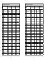 41
41
-
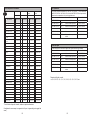 42
42
-
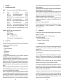 43
43
-
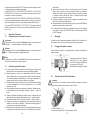 44
44
-
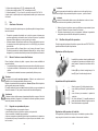 45
45
-
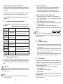 46
46
-
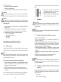 47
47
-
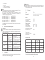 48
48
-
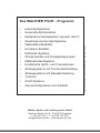 49
49


WALTHER PILOT PILOT WA 705 Istruzioni per l'uso
- Tipo
- Istruzioni per l'uso
- Questo manuale è adatto anche per
in altre lingue
Documenti correlati
-
WALTHER PILOT WA 700 Istruzioni per l'uso
-
-
-
-
-
-
-
-
Altri documenti
-
3M Accuspray™ ONE Spray Gun Kit Istruzioni per l'uso
-
Parkside PDFP 500 A1 Operation and Safety Notes
-
-
-
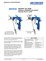 Binks Trophy AA1600 & AA4400 Manuale utente
-
Optima OPTIMA 650 I S Manuale utente
-
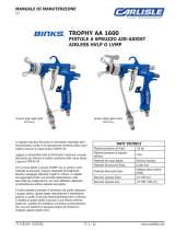 Binks Trophy AA1600 & AA4400 Manuale utente
-
T'nB RCOLORCH Manuale utente
-
Anest Iwata TOF-5B Manuale utente
-
Sagola 3300 Pro Manuale utente

