ROBLIN LINEAR CENTRALE 1500 Manuale del proprietario
- Categoria
- Cappe da cucina
- Tipo
- Manuale del proprietario

LINEAR Centrale 1500
NOTICE D’INSTALLATION ET D’UTILISATION
INSTRUCTIONS FOR INSTALLATION AND DIRECTIONS FOR USE
MONTAGE- UND GEBRAUCHSANWEISUNG
LIBRETTO DI ISTRUZIONI
INSTRUCCIONES DE INSTALACION E UTILIZACION
MONTAGE- EN GEBRUIKSHANDLEIDING

F SOMMAIRE
RACCORDEMENT ÉLECTRIQUE
CONSEILS D’INSTALLATIONS
POSE DE L’APPAREIL
FONCTIONNEMENT
CONSEILS D’UTILISATIONS
ENTRETIEN
GARANTIE ET SERVICE APRÈS-VENTE
REMARQUES
D INHALT
NETZANSCHLUSS
MONTAGEHILFEN
MONTAGE DES GERÄTES
BETRIEB DES GERÄTES
NUTZUNG
WARTUNG UND REINIGUNG
GARANTIE UND KUNDENDIENST
WICHTIGE HINVEISE
E SUMARIO
CONEXION ELECTRICA
CONSEJOS DE INSTALACION
INSTALACION DEL APARATO
FUNCIONAMIENTO
CONSEJOS DE UTILIZACION
MANTENIMIENTO
GARANTIA Y ASSISTENCIA TECNICA
NOTA
GB CONTENTS
ELECTRICAL WIRING
INSTALLATION ADVICE
FITTING THE APPLIANCE
OPERATION
USEFUL HINTS
MAINTENANCE
GUARANTEE AND AFTER-SALES-SERVICES
REMARKS
I CONTENUTI
COLLEGAMENTO ELETTRICO
CONSIGLI DI INSTALLAZIONE
POSA DELL’ APPARECCHIO
FUNZIONAMENTO
CONSICLI DI UTILIZZO
MANUTENZIONE
GARANZIA ED ASSISTENZA TECNICA
NOTE
NL INHOUD
ELECTRISCHE BEDRADING
MONTAGE AANWIJZING
AANSLUITEN VAN HET APPARAAT
FUNKTIONEREN
GEBRUIKSADVIES
ONDERHOUD
AFTER SALES SERVICE
OPMERKINGEN

1
F
Nous vous remercions de la conance que vous nous avez accordée en choisissant un appareil de la
gamme ROBLIN.
Celui-ci a fait l’objet de toute notre attention dans sa conception et sa réalisation.
An qu’il vous donne entière satisfaction, nous vous recommandons de lire avec attention cette notice
qui vous expliquera comment l’installer, l’utiliser et l’entretenir dans les meilleures conditions.
La présente notice d’emploi vaut pour plusieurs versions de l’appareil. Elle peut contenir des descriptions
d’accessores ne gurant pas dans votre appareil.
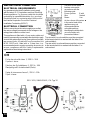
1 RACCORDEMENT ÉLECTRIQUE.
• La hotte est équipée d’un cordon d’alimentation de type HO5VVF 3 x 0,75 mm² comportant une
che normalisée 10/16 A avec système de mise à la terre.
Mode de protection : classe 1. Tension d’alimentation : 220-240 V mono - 50/60Hz.
Vérier que la tension du secteur est identique aux valeurs indiquées sur la plaque signalétique à l’inté-
rieur de la hotte
• Si la hotte est raccordée directement sur le réseau sans sa che, un interrupteur omnipolaire avec
une ouverture de contact de 3 mm doit être installé avant la hotte. Le l de terre (Jaune / vert) ne doit pas
être interrompu par cet interrupteur.
2 CONSEILS D’INSTALLATION.
• Pour un fonctionnement idéal, nous vous conseillons une plage de hauteur de pose qui se situe de
0,65 m à 0,70 m au-dessus du plan de cuisson. Toutefois, il est formellement interdit d’installer toute
hotte ou groupe d’aspiration à une distance inférieure à 0,65 m du plan de travail (risque d’inammation
des ltres). La fumée doit monter naturellement vers la zone de captation.
• Respecter le diamètre de sortie de l’appareil : la hotte ne doit en aucun cas être raccordée à un
conduit de ventilation mécanique contrôlée (V.M.C.).
• Lorsqu’on évacue l’air vicié dans un conduit d’évacuation, veiller à ce que celui-ci ne soit pas déjà
exploité à véhiculer des gaz ou fumées provenant d’appareils alimentés par une énergie autre qu’électri-
que.
• Positionner le plan de cuisson au plus près de l’évacuation et éviter la formation de coudes sur la
gaine, an de réduire au maximum les pertes de charges.
• Dans tous les cas d’installation, veiller au bon renouvellement d’air de la cuisine. Penser à effectuer
une ou des entrées d’air par une grille de section égale ou supérieure au diamètre du tuyau
d’évacuation, an de ne pas mettre la cuisine en dépression.
• Prévoir une aération sufsante lorsqu’un appareil de cuisson ou autre utilise simultanément l’air
ambiant de la pièce où est installée la hotte.
• La dépression maximum crée dans la pièce doit être inférieure à 0.04 mbar, ce qui évite un retour de
gaz de combustion.
• L’appareil doit être positionné de telle façon que la che d’alimentation soit accessible.
• Cet appareil ne doit pas être utilisé par des personnes (y compris les enfants) ayant des capacités psy-
chiques, sensorielles ou mentales réduites, ni par des personnes n’ayant pas l’expérience et la connais-
sance de ce type d’appareils, à moins d’être sous le contrôle et la formation de personnes responsables
de leur sécurité.
Les enfants doivent être surveillés pour s’assurer qu’ils ne jouent pas avec l’appareil.
3 POSE DE L’APPAREIL.
Montage et raccordement doivent être réalisés par un installateur* qualié.
(*) Le non-respect de cette condition entraîne la suppression de la garantie du constructeur et
tout recours en cas d’accident.
Attention: prendre bien soin d’employer les chevilles adaptées au support, se renseigner au près
des fabricants, effectuer un scellement si nécessaire. La société décline toute responsabilité en

2
F
cas d’accrochage défectueux dû au perçage et chevillage.
•
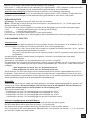
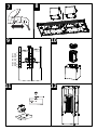
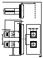
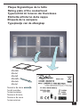
PERCAGE DU PLAFOND
1. A l'aide d'un l à plomb reporter au plafond le centre du plan de cuisson. Tracer les axes parallèlement
au plan de cuisson. (g 1)
2. Positionner le gabarit de perçage en alignant les axes tracés et les découpes triangulaires du gabarit
(g 2). Le gabarit peut être xé provisoirement par les 5 trous Ø 4.5 an de faciliter le traçage.
3. Tracer les centres des différents perçages à effectuer.
- 8 trous repérés par les Ø 12 du gabarit . Les diamètres de ces trous sont à dénir selon le mode
de xation dans le plafond, sachant que les supports de hotte seront xés avec des goujons
ou des vis de Ø 12
- 2 trous repérés par les Ø 200 du gabarit lorsque les sorties d'air traversent le plafond. Leurs
diamètres sont à dénir suivant la section de la tuyauterie.
- Prévoir aussi l'alimentation électrique.
4. Percer les différents trous. Si le plafond vous semble de solidité douteuse, n'hésitez pas à le renforcer
dans les combles (g. 3) ou par tout autre moyen.
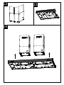
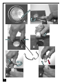
• FIXATION DES SUPPORTS DE HOTTE
1. Enlever les supports de hotte des conduits d'habillage. (g 4)
2. Pour la version recyclage, déposer le diffuseur (g 5)
3. A l'aide de tiges letées ou de vis Ø 12, xer solidement les supports au plafond. Dans le cas d'une
version recyclage, remonter le diffuseur.
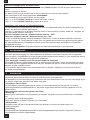
• FIXATION DES BLOCS D'ASPIRATION SUR LES SUPPORTS
1. Pour les versions Evacuation Extérieure, enlever les déecteurs du plateau (g 6)
2. Pour les versions motorisées, déconnecter la che 6 voies (g 7)
3. Désolidariser les blocs d'aspiration du plateau de la hotte (g 8)
4. Régler les supports de hotte sur les blocs d'aspiration à la hauteur désirée. Votre hotte est réglable
en hauteur par tranche de 50 mm ; les 8 vis 5 x 10 T. Hexagonale se logent dans les trous oblongs
permettant une mise à l'aplomb. (g 9). Les pastilles de couleur denissent l’orientation des blocs
d’aspiration par rapport au plateau.
5. Vérier l'aplomb et le parallélisme des colonnes.
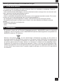
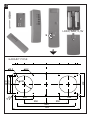
• RACCORDEMENT
Pour les versions Evacuation Extérieure
1. Mettre en place les manchons d'insonorisation puis les clapets anti-refoulement. (Fig 10)
2. Raccorder les tuyauteries d'évacuations aux buses moteurs . Fixer l'ensemble à l'aide de colliers ou
de ruban adhésif appropriés.
3. Raccorder les prises électriques
Pour les versions Moteur à Distance
1. Raccorder les tuyauteries aux buses d'aspiration. Fixer l'ensemble à l'aide de colliers ou de ruban
adhésif appropriés.
2. Raccorder les ls de terre et clipper les connecteurs des moteur à distance sur les couvercles des
blocs d'aspirations. (g 11)
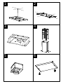
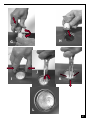
Pour les versions Recyclage
1. Raccorder les tuyaux fournis aux buses des diffuseurs. Si nécessaire, recouper les tuyaux à longueur
désirée et les raccorder aux buses moteur. (g 12) Fixer l'ensemble à l'aide de colliers ou de ruban
adhésif appropriés.
2. Raccorder les prises électriques
• POSE DES CONDUITS D'HABILLAGE
1. Monter les parties supérieures des conduits sur les supports de hottes. Les xer par leurs vis (g 4)
2. Vérier de nouveau l'aplomb et le parallélisme des colonnes.
3. Enler las parties inférieures sur les parties supérieures des conduits. Les maintenir en position en

3
F
dévissant légèrement 2 vis des conduits supérieurs. (g 13)
• POSE DU PLATEAU DE HOTTE
1. Présenter le plateau sous les colonnes et le xer les 8 vis CHC M5 fournies. (g 14)
2. Revisser les vis des conduits supérieurs et abaisser les conduits inférieurs.
3. Connecter les connecteurs 6 voies du plateau sur les connecteurs moteurs. (g 7)
4. Pour les versions Recyclage, placer les cartouches à charbon actif dans leurs logements en exerçant
une pression sur les languettes A (g. 15).
5. Pour les versions Evacuation Extérieure, rexer les déecteurs par leur vis (g 6) .
6. Placer les ltres métalliques..
4 FONCTIONNEMENT
a) Conguration
Evacuation extérieure ou recyclage :
Votre hotte est programmée pour fonctionner en mode évacuation extérieure. Si vous souhaitez l’utiliser en
mode recyclage, vous devez impérativement la congurer suivant la procédure suivante :
Mise en recyclage ( l’air est ltré puis renvoyé dans la cuisine) :
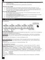
Moteur et éclairage éteints, appuyer sur la touche (+) jusqu’aux clignotements des 5 leds :
Deux clignotements des 5 leds indiquent l’enregistrement de la mise en recyclage.
Retour en mode évacuation ( L’air est ltré puis évacué à l’extérieur de l’habitation):
Moteur et éclairage éteints, appuyer sur la touche (+) jusqu’aux clignotements des 5 leds :
Un clignotement des 5 leds indiquera l’enregistrement de la mise en évacuation extérieure.
b) Fonctions de base :
Eclairage :
Mise en marche en appuyant sur la touche 1 (lumière). La led 1 visualise l’état de l’éclairage
Moteur :
Mise en marche en appuyant sur la touche 2 (moteur). Il est possible de modier le débit d’aspiration de
la hotte à l’aide des touches vitesse + et vitesse – , en gardant la touche enfoncée jusqu’à l’obtention de
la vitesse désirée. Le niveau de vitesse est visualisé par les leds 2, 3, 4 qui s’allument au fur et à mesure
de l’accroissement de la vitesse :
Led 2 = niveau minimum
Led 2 et 3 = niveau intermédiaire
Led 2, 3 et 4 = niveau élevé
Un débit d’aspiration maximal peut être obtenu directement en appuyant sur la touche vitesse intensive
(5 ).F
c) Fonctions complémentaires :
• Vitesse intensive temporisée
Pour obtenir une bonne efcacité d’évacuation, nous vous conseillons en début de cuisson une période de
fonctionnement en position intensive. Elle créera un ux d’air permettant de capter les premières fumées
ou vapeurs dès leur apparition. Pour cette fonction il convient de suivre la procédure suivante :
- Mettre le moteur en marche (touche 2), puis sélectionner à l’aide des touches (+) et (-) la vitesse souhaitée

4
F
pendant la cuisson.
- Appuyer sur la touche 5 (vitesse intensive). Cette fonction peut être arrêtée en appuyant à nouveau sur
la touche 5.
Temporisation de 5 minutes de l’arrêt de la vitesse intensive:
Par défaut cette fonction n’est pas activée.
Pour accéder à la programmation de cette fonction, la lumière doit être éteinte et le moteur arrêté.
Appuyer sur la touche réglage vitesse (-) :
Un clignotement des Leds 2, 3, et 4 = fonction désactivée.
Deux clignotements des Leds 2, 3, et 4 = fonction activée.
Il est possible d’arrêter manuellement la vitesse intensive avant le délai de 5 minutes en appuyant à nouveau
sur la touche 5 (Vitesse intensive).
Pendant cette temporisation de 5 minutes, l’indication de saturation ltres est désactivée.
Si un arrêt différé de la hotte est programmé, la vitesse intensive commandée manuellement ou temporisée
sera désactivée par cet arrêt différé après 5, 10 ou 15 minutes. Il est possible d’arrêter manuellement la vi-
tesse intensive avant l’arrêt différé de la hotte en appuyant à nouveau sur la touche 5 (Vitesse intensive).
• Arrêt différé :
Cette fonction permet, après l’arrêt de la cuisson, d’évacuer les dernières fumées et odeurs résiduelles
et en n de cuisson, d'arrêter totalement la hotte (moteur + éclairage).
Pour accéder à la programmation de ce réglage la lumière doit être éteinte et le moteur arrêté.
Appuyer sur la touche vitesse intensive 5 :
- 2 clignotements des leds 1 & 5 conrmeront l’enregistrement de l’arrêt après 5 minutes.
- 3 clignotements des leds 1 & 5 conrmeront l’enregistrement de l’arrêt après 10 minutes.
- 4 clignotements des leds 1 & 5 conrmeront l’enregistrement de l’arrêt après 15 minutes.
- 1 seul clignotement des leds 1 & 5 conrmera la suppression de la fonction arrêt différé.
La hotte peut ensuite être mise en marche sur la vitesse choisie. Le clignotement des leds 2, 3, 4 (sui-
vant la vitesse initialement prévue) indiquera que la fonction arrêt différé est bien programmée :
- 1 clignotement = arrêt après 5 minutes
- 2 clignotements = arrêt après 10 minutes
- 3 clignotements = arrêt après 15 minutes
• Indication de saturation des ltres métalliques :
Après 200 heures de fonctionnement 1 bref clignotement de la Led 1 indique qu’il faut nettoyer les
ltres métalliques (voir paragraphe entretien)
Pour accéder à la remise à zéro de la fonction indiquant la saturation des ltres, la lumière doit être
éteinte et le moteur arrêté.
Appuyer sur la touche (+) pendant 3 à 4 secondes. Le clignotement des Leds 1, 2, 3, 4, et 5 conrme la
remise à zéro.
• Indication de saturation des ltres charbon :
Après 400 heures de fonctionnement 2 brefs clignotements de la Led 1 indique qu’il faut remplacer
les ltres charbon et nettoyer à nouveau les ltres métalliques.
Pour activer la fonction Indication de saturation ltre charbon, la lumière doit être éteinte et le moteur
arrêté. Appuyer sur la touche (+) pendant 10 secondes.
1 clignotement des Leds 1, 2, 3, 4, et 5 = fonction désactivée.
2 clignotements des Leds 1, 2, 3, 4, et 5 = fonction activée.
La méthode de remplacement de la cartouche est indiquée au paragraphe 3 (Recyclage)
• Conguration réception télécommande :
Votre hotte est programmée pour fonctionner sans réception télécommande. Si vous souhaitez l’utiliser
avec la télécommande, vous devez impérativement la congurer suivant la procédure suivante :
Moteur et éclairage éteints, appuyer sur la touche 1 (éclairage) jusqu’au clignotement de la led 1 :
Deux clignotements de la led 1 indiquent que la télécommande est activée.
Un clignotement de la led 1 indique que la télécommande est désactivée.
Attention, la télécommande doit être équipée de piles alcalines standards : LR003-AAA, 1.5V comme décrit

5
Fig. 16. Ces piles devraient assurer un usage optimum de longue durée et doivent être positionnées cor-
rectement, elles peuvent exploser si elles sont endommagées ou exposées à la chaleur. Ne pas les jeter
dans le feu. An de préserver l’environnement, merci de déposer ces piles dans un conteneur approprié.
5 CONSEILS D’UTILISATION
• Pour obtenir une efcacité maximum d’absorption des fumées ou des vapeurs, faire fonctionner
l’appareil 5 minutes environ avant et après la cuisson des aliments; La première vitesse est conseillée
pour les cuissons à feu doux et pour les sauces. La deuxième pour les cuissons soutenues, grillades et
friteuses. La troisième est indiquée pour les cuissons à forte émanation de graisses et vapeur.
• IMPORTANT . NE JAMAIS FLAMBER DE METS AU DESSOUS DE L’APPAREIL
Ne laissez jamais de ammes libres sous la hotte en fonctionnement.
• Les fritures nécessitent une surveillance permanente, l’huile surchauffée pouvant s’enammer.
6 ENTRETIEN
Déconnecter le câble d’alimentation pour toute intervention électrique.
L’appareil a été conçu pour faciliter au maximum les opérations d’entretien, synonyme de bon fonctionne-
ment et rendement de l’appareil dans le temps.
• Nettoyage des ltres métalliques.
Il est indispensable de procéder à un NETTOYAGE PÉRIODIQUE de ces ltres à la main (avec un
détergent liquide à l’eau tiède et rinçage) ou au lave- vaisselle (tous les deux mois environ pour une
utilisation normale).
• Carrosserie.
Nettoyer régulièrement celle-ci en utilisant des produits détergents, non abrasifs et une éponge légère-
ment humide. N’utilisez jamais d’éponges ou de chiffons trempés.
N’introduisez aucun objet, ni les mains dans l’ouverture servant à l’évacuation de l’air.
• Conduit d’évacuation.
Vérier tous les 6 mois le bon écoulement de l’air vicié.
Observer les prescriptions réglementaires locales concernant l’évacuation de l’air vicié.
• Éclairage.
Avant toute intervention sur l’appareil, mettre l’interrupteur d’allumage des lampes en position éteinte.
Ne pas dépasser la puissance prescrite et ne pas changer de type de lampe.
7 GARANTIE ET SERVICE APRÈS-VENTE
• En cas d’anomalie de fonctionnement, prévenez votre installateur qui devra vérier l’appareil et son
raccordement.
• Dans le cas où un composant électrique viendrait à être endommagé, celui-ci ne peut être remplacé
que par un atelier de réparation reconnu par le fabricant, car des outils spéciaux sont nécessaires.
• Débrancher complètement l’appareil.
• Exigez toujours l’utilisation de pièces de rechange d’origine. La non observation de cette prescription
peut compromettre la sécurité de l’appareil.
• Lors de la commande de pièces détachées, rappeler le numéro de l’appareil inscrit sur la plaque
signalétique située à l’intérieur de la hotte.
• Seule la facture d’achat de l’appareil fera foi pour l’application de la garantie contractuelle.
Cette garantie ne couvre pas les consommables comme :
- L’éclairage : lampes incandescentes, halogènes ...
- Les ltres.
8 REMARQUES
Cet équipement est conforme à la norme européenne sur la basse tension 2006/95/CE relative à la sé-
curité électrique et aux normes européennes: 2004/108/CE relative à la compatibilité électromagnétique
et 93/68 relative au marquage CE.
F

6
Lorsque ce symbole d’une poubelle à roue barrée est attaché à un produit, cela signie que le
produit est couvert par la Directive Européenne 2002/96/EC. Votre produit est conçu et fabriqué avec
des matériaux et des composants de haute qualité, qui peuvent être recyclés et utilisés de nouveau.
Veuillez vous informer du système local de séparation des déchets électriques et électroniques. Veuillez
agir selon les règles locales et ne pas jeter vos produits usagés avec les déchets domestiques usuels.
Jeter correctement votre produit usagé aidera à prévenir les conséquences négatives potentielles contre
l’environnement et la santé humaine.
8 REMARQUES
F

7
GB
Thank you for buying a Roblin product which has been manufactured to the highest quality standards to
meet your requirements.
We recommend you carefully read this booklet in which you will nd instructions for installation, hints for
use and maintenance.
The Instructions for Use apply to several versions of this appliance. Accordingly, you may nd descrip-
tions of individual features that do not apply to your specic appliance.
1 ELECTRICAL
• This cooker hood is tted with a 3-core mains cable with a standard 10/16A earthed plug.
• Alternatively the hood can be connected to the mains supply via a double-pole switch having 3mm
minimum contact gap on each pole.
• Before connecting to the mains supply ensure that the mains voltage corresponds to the voltage on
the rating plate inside the cooker hood.
• Technical Specication: Voltage 220-240, single phase ~50/60Hz.
2 INSTALLATION ADVICE
• Ensure the cooker hood is tted in compliance with the recommended xing heights.
• To ensure the safe operation of this cooker hood, we recommend that the hood should not be tted
below 65cm (for electric) or (70cm for gas) the measurements taken from the surface of the cooking
appliance to the underside of the cooker hood.
• It is a possible re risk if the hood is not sited as recommended.
• To ensure the best results, the cooking fumes should be able to rise naturally towards the inlet grilles
on the underside of the cooker hood and the cooker hood should be positioned away from doors and
windows, which will create turbulence.
• Ducting
• If the room where the hood is to be used contains a fuel-burning appliance such as a central heating
boiler then its ue must be of the room sealed or balanced ue type.
• If other types of ue or appliances are tted ensure that there is an adequate supply of fresh air to the
room. Ensure the kitchen is tted with an airbrick, which should have a cross-sectional measurement
equivalent to the diameter of the ducting being tted, if not larger.
• The ducting system for this cooker hood must not be connected to any existing ventilation system,
which is being used for any other purposes or to a mechanically controlled ventilation ducting.
• The ducting used must be made from re retardant materials and the correct diameter must be used,
as incorrect sized ducting will affect the performance of this cooker hood.
• When the cooker hood is used in conjunction with other appliances supplied with energy other than
electricity, the negative pressure in the room must not exceed 0.04 mbar to prevent the fumes from
combustion being drawn back into the room.
• The appliance is for domestic use only and should not be operated by children or people who are
inrm without supervision.
• This appliance must be positioned so that the wall socket is accessible.
• This appliance is not intended for use by persons (including children) with reduced physical, sensory
or mental capabilities, or lack of experience and knowledge, unless they have been given supervision or
instruction concerning use of the appliance by a person responsible for their safety.
Children should be supervised to ensure that they do not play with the appliance.
3 FITTING
Any permanent electrical installation must comply with the latest regulations concerning this type of
installation and a qualied electrician must carry out the work. Non-compliance could cause serious
accidents or injury and would deem the manufacturers guarantee null and void.
IMPORTANT - The wires in this mains lead are coloured in accordance with the following code :
- green / yellow : earth - blue : neutral - brown : live
As the colours of the wires in the mains lead of this appliance may not correspond with the coloured

8
GB
markings identifying the terminals in your plug, proceed as follows.
- The wire which is coloured green and yellow must be connected to the terminal in the plug which is
marked with the letter E or by the earth symbol or coloured green or green and yellow.
- The wire which is coloured blue must be connected to the terminal which is marked with the letter N or
coloured black.
- The wire which is coloured brown must be connected to the terminal which is marked with the letter L or
coloured red.
ATTENTION: Do not forget to use adequate plugs to the support brackets. Enquire after the manu-
facturers. Do an embedding if necessary. The manufacturer accepts no responsibility in case of a
faulty hanging due to the drilling and the setting up of plugs.
GB
• LAYING OUT BEFORE FITTING THE HOOD
1. Mark the centre of the cooking appliance onto the ceiling with a plumb line. Draw the horizontal axes
running parallel to the stove top onto the ceiling as illustrated Fig. 1.
2. Place the drill gauge centred on the axes aligning the notches on the drill gauge centrally over these
axes as illustrated Fig. 2. The drill gauge could be temporarily xed onto the ceiling with the 5 holes
Ø 4.5 mm while the laying out operation.
3. Mark the positions on the ceiling for : - The 2 cut-out for the ducting Ø 150 mm in the extrac-
tion mode and Ø 200 mm in the remote mode when ducting runs through the ceiling.
- The 2 mains supply cords.
- The 8 xing holes for Ø 12 mm nuts and bolts.
4. Drill the different holes with the appropriate masonry bit. If the ceiling is concrete, use eight Ø 12 mm
steel rawl bolts. Plastic rawl plugs must not be used.
• FITTING THE CANOPY BRACKETS
1. Unscrew the eight self tapping screws and remove both sides of the 2 upper chimney stacks as
illustrated Fig. 4.
2. In the recirculation mode remove the two recirculation spigot as illustrated Fig. 5.
3. Fitting the two chimney brackets with the appropriate Ø 12 mm nuts and bolts . When xing the
brackets to a plasterboard ceiling ensure it is reinforced as illustrated Fig. 3 and attach using eight
Ø 12 mm nuts and bolts , ensuring the bolts as sleeved between the plasterboard and joist supports
to prevent the ceiling been damaged when the bolts are tightened up.
In the recirculation mode t back the two recirculation spigots.
• FITTING THE MOTORS IN THE TWO CHIMNEY BRACKETS
1. In the extraction mode remove the two deectors Fig. 6.
2. When canopy is equipped with motors unplug the two connectors 6 ways Fig. 7.
3. Separate the two motor housing from the canopy Fig. 8.
4. The height of the cooker hood can be adjusted in 50 mm stages. 650 mm when tting above an
electric hotplate and 700 mm when tting above a gas hotplate. Select the height required using the
measurements illustrated in Fig. 9 and x the two metal diffusers to the frame of the chimney brackets
using the twice height 5 x 10T hexagonal headed screws. A spot of coloured paint on the diffusers
denes the positioning for the controls.
5. Check the vertical and parallelism of the two chimneys.
• DUCTING
The hood is more effective when used in the extraction mode ( ducted to the outside). When the cooker
hood is ducted to the outside, charcoal lters are not required.
The ducting used must be 150 mm (6 ins), rigid circular pipe and must be manufactured from re retar-
dant material, produced to BS.476 or DIN 4102-B1. Wherever possible utilise rigid circular pipe which
has a smooth interior, rather than the expanding concertina type ducting.
Maximum length of ducting run :

9
- 4 metres with 1 x 90° bend.
- 3 metres with 2 x 90° bends.
- 2 metres with 3 x 90° bends.
The above assumes our 150 mm (6 ins) ducting is being installed. Please note ducting components and
ducting kits are optional accessories and have to be ordered, they are not automatically supplied with
the chimney hood.
IN THE EXTRACTION MODE :
1. Fit the noise-reduction tubes over the round outlets on top of the canopy while pressing down until
they snap into position and then t the non-return backow aps onto the top of the noise-reduction
tubes as illustrated Fig. 10.
2. Connect the ducting 150mm ( 6ins) and secure the connections with appropriate clamping rings or
adhesive tape.
3. Make the electrical connections as described in the section titled ELECTRICAL.
IN THE REMOTE INSTALLATION MODE :
1. Connect the ducting 200 mm ( 8ins) onto the round outlets on the top of the canopy and onto the
round inlet of the motors at a distance and secure the connections with appropriate clamping rings
or adhesive tape.
2. Connect the earth connections onto the terminals marked with the earth symbol and clamp the con-
nectors onto the motors housing as illustrated Fig. 11.
IN THE RECIRCULATION MODE :
1. Connect the ducting 150mm ( 6ins) between motors and the recirculation spigot as illustrated Fig. 12
and secure the connections with appropriate clamping rings or adhesive tape.
2. Before tting the chimneys to the canopy make the electrical connections as described in the section
titled ELECTRICAL.
• FITTING THE CHIMNEY STACK
1. Fix both sides of the 2 upper chimney stacks as illustrated in Fig. 4 using the screws provided.
2. Check again vertical and parallelism of the two chimneys.
3. Pull on the two lower chimneys and secure them temporarily unscrewing a little bit the lower self
tapping screws as illustrated in Fig 13.
• FITTING THE CANOPY ONTO THE TWO CHIMNEYS
1. Place the canopy under the two chimneys and x it with the eight CHC M5 screws provided as il-
lustrated in Fig. 14.
2. Screw the lower self tapping screws of the two upper chimneys and t the two lower chimney sections
by expending slightly them onto the canopy .
3. Connect the 6 ways connectors onto the right hand side of the two motors as illustrated in Fig. 7.
4. In the recirculation mode, remove the metal grease lters and insert the charcoal lters into the bases
of the 2 motor housing and secure the charcoal lters with the securing straps item A as illustrated in
g. 15.
6. In the extraction mode t the two deectors as illustrated in Fig. 6.
5. Fit the metal grease lters.
GB

10
4 OPERATION
A - EXTRACTION OR RECYCLING :Your cooker hood is supplied in the extraction mode. To use the cooker
hood in the recycling mode re-programme the hood as follows:
Starting in the recycling mode (the contaminated air passes into the hood through the grease lters and
the purifying activated charcoal lter and back out into the kitchen through grilles).
Press the ‘+’ button (while the motor and lights are switched ‘OFF’) until the ve LED lights will ash twice
to indicate conrmation that the cooker hood is in the recycling mode.
Reverting to the extraction mode (The cooker hood is ducted to the outside).
Press the ‘+’ button (while the motor and lights are switched ‘OFF’) until the ve LED lights will ash once
to indicate conrmation that the cooker hood is in the extraction mode.
GB
B - BASIC INSTRUCTIONS
Lighting
Press LED button 1 to switch ‘ON’ the lights and the LED will illuminate to conrm the lights are switched
‘ON’.
Motor
Press LED button 2 to switch ‘ON’ the fan motor (and adjust the speed of the fan motor by pressing the
LED button ‘+’ and ‘-‘) and the LED lights 2, 3 and 4 will illuminate. The fan speed will be increased if
constant pressure is kept on the (+) button.
LED 2 : Minimum speed - cooking with one pan or simmering
LED 2 & 3 : Medium speed - normal cooking with up to 4 pans
LED 2, 3 & 4 : Maximum speed - frying and cooking foods with strong odours
Press LED button 5 to obtain the boost position for maximum effect and the LED will illuminate to conrm
fan is switched ‘ON’.
C - COMPLEMENTARY INSTRUCTIONS
• Boost speed :
To obtain the best performance it is advisable to switch ‘ON’ the cooker hood a few minutes (in the boost
setting) before you start cooking. To program the complementary function, proceed as follows:
- Press LED button 2 to switch ‘ON’ the fan motor and adjust the speed of the fan by pressing the LED
button ‘+’ and ‘-‘. You should keep applying pressure to the ‘+’ and ‘-‘ button until the required speed is
selected.
- Press LED button 5 (boost speed) to switch ‘ON’ the fan motor in the boost setting. Press LED button 5
to switch ‘OFF’ the boost setting immediately.
It is advisable too that you should leave it running in the boost setting for approximately 5 minutes after
nishing.
• Pre-set stop of the boost speed :
A pre-set stop after 5 minutes of the boost speed is available.
Your cooker hood is supplied with a deactivated pre-set stop of the boost speed. To use the cooker hood
GB

11
with a pre-set stop of the boost speed re-programme the hood as follows:
The lights and the fan motor should be switched ‘OFF’ to set the timer.
Push the LED button ‘-’ until the LED lights will ash :
One ash of the LED lights 2,3, and 4 = function is switched ‘OFF’.
Two ashes of the LED lights 2,3, and 4 = function is switched ‘ON’.
While the 5 minutes timer is running, It is available to stop immediately the boost speed by pressing the
led button 5.
While the 5 minutes timer is running, the indication of saturation of the lters is switched ‘OFF’.
If a pre-set stop for the hood is switched ‘ON’ and the 5 minutes timer is still running, the boost speed will
be switched ‘OFF’ together with the pre-set stop for the hood after the count down of 5, 10 or 15 minutes.
It is available to stop the boost speed before the count down of the preset stop of the hood by pressing
the led button 5.
• Pre-set stop for the hood :
This function allows you to program the cooker hood to automatically stop cooking after a pre-set period.
The lights and the fan motor should be switched ‘OFF’ to set the timer.
Proceed by repeatedly pressing the LED button 5 (Boost speed):
Two ashes of the LED button 1 & 5 = 5 minutes delay.
Three ashes of the LED button 1 & 5 = 10 minutes delay.
Four ashes of the LED button 1 & 5 = 15 minutes delay.
One ash of the LED button indicates the function is switched ‘OFF’.
You can switch the cooker hood ‘ON’ and adjust the speed. The LED buttons 2, 3 and 4 will ash to
indicate the fan motor is switched ‘ON’ and which speed has been selected.
One ash = stop after 15 minutes.
Two ashes = stop after 10 minutes.
Three ashes = stop after 15 minutes.
• Indication of saturation of the metal grease lters :
After 200 hours use, one quick ash of the LED 1 will indicate that you must clean the metal grease
lters. (See chapter on ‘Maintenance’).
To reset the 200 hours timer back to zero requires the motor and lights must be switched ‘OFF’; then and
proceed as follows:
Press the LED button ‘+’ for 3 to 4 seconds and the LED lights 1,2,3, 4 and 5 will ash to conrm the
programme has been reset to zero.
8GB
• Indication of saturation of the active charcoal lter :
After 400 hours use, two quick ash of the LED 1 will indicate that you must replace the active charcoal
lter and clean the metal grease lters. (See chapter on ‘Maintenance’).
To reset the 400-hour timer the motor and lights must be switched ‘OFF’.
Push the LED button ‘+’ for 10 seconds.
One ash of the LED lights 1,2,3,4 and 5 = function is switched ‘OFF’.
Two ashes of the LED lights 1,2,3,4 and 5 = function is switched ‘ON’.
Instructions for replacing the active charcoal lter are given in the chapter on ‘Recycling’.
• Pre-set remote control handset
Your cooker hood is supplied with a deactivated remote control receiver. To use the cooker hood with a
remote control re-programme the hood as follows:
Press the LED button (Lighting) ‘1’ while the motor and lights are switched ‘OFF’, until the LED lights 1 will
ash to conrm the programme has been activated :
One ash of the LED lights 1 = function is switched ‘OFF’.
Two ashes of the LED lights 1 = function is switched ‘ON’.
Caution, the remote control handset must be tted with standard LR03-AAA size 1.5V zinc-carbon alkaline
batteries as illustrated Fig. 16. These batteries should give a long life and constant discharge throughout
GB

12
their life. These batteries must be disposed of properly and could explode if damaged or exposed to heat.
Do not dispose of on re. Dispose of batteries in the appropriate sort container to protect the environ-
ment.
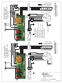
• Setup Process
Modication: How to adjust the internal microprocessor data to suit the type of motor tted to this
appliance and the supply frequency of 50 or 60 Hz..
1 - Disconnect the cooker hood from the mains supply.
2 - Push the button 0/1 MOTOR.
3 - Reconnect the mains supply while pushing the button 0/1 MOTOR for at least 2 seconds.
4 - Release the button 0/1 MOTOR (the Leds ash for about 3 seconds : capacity’s conrmation SETUP
PROCESS).
5 - While the LED is ashing select the motor type used while pushing one of the 5 buttons in accordance
with the following:
BUTTON 0/1 Light : Motor EBM PRO 220-240 V AC 50 Hz / 220 V AC 60 Hz.
BUTTON 0/1 Motor : Motor FABER 8/28 e 8/50 220-240 V AC 50 Hz / 220 V AC 60 Hz.
BUTTON Speed ( - ) : Motor EBM MISTRAL 220-240 V AC 50 Hz / 220 V AC 60 Hz.
BUTTON Speed (+ ) : Motor EBM PRO 220-240 V AC 50 Hz / 220 V AC 60 Hz.
BUTTON Intensive speed : Motor FABER K40-K50 220-240 V AC 50 Hz / 220 V AC 60 Hz.
N.B. : If you have not selected a motor type while the LED is ashing the microprocessor will automatically
select the default motor EBM PRO 220 - 240 V AC 50 Hz / 220 V AC 60 Hz.
5 USEFUL HINTS
• To obtain the best performance it is advisable to switch ‘ON’ the cooker hood a few minutes (in the
boost setting) before you start cooking and you should leave it running for approximately 15 minutes after
nishing.
• IMPORTANT: NEVER DO FLAMBÉ COOKING UNDER THIS COOKER HOOD
• Do not leave frying pans unattended during use as over-heated fat and oil might catch re.
• Do not leave naked ames under this cooker hood.
• Switch ‘OFF’ the electric and gas before removing pots and pans.
• Ensure heating areas on your hotplate are covered with pots and pans when using the hotplate
and cooker hood simultaneously.
6 MAINTENANCE
Before carrying out any maintenance or cleaning isolate the cooker hood from the mains supply.
The cooker hood must be kept clean; a build up of fat or grease can be a re hazard.
Casing
• Wipe the cooker hood frequently with a clean cloth, which has been immersed in warm water containing
a mild detergent and wrung out.
• Never use excessive amounts of water when cleaning particularly around the control panel.
• Never use scouring pads or abrasive cleaners.
• Always wear protective gloves when cleaning the cooker hood.
Metal Grease Filters
The metal grease lters absorb grease and dust during cooking to help keep the cooker hood clean
inside. The grease lters should be cleaned once a month or more frequently if the hood is used for more
than 3 hours per day.
To remove and replace the metal grease lters
• Remove the metal grease lters one at a time by releasing the catches on the lters; the lters can
now be removed.
GB

13
GB
• The metal grease lters should be washed, by hand, in mild soapy water or in a dishwasher.
• Allow to dry before replacing.
Active Charcoal Filter
The charcoal lter cannot be cleaned. The lter should be replaced at least every three months or more
frequently if the hood is used for more than three hours per day.
To remove and replace the lter
• Remove the metal grease lters.
• Press against the two retaining clips, which hold the charcoal lter in place and this will allow the lter
to drop down and be removed.
• Clean the surrounding area and metal grease lters as directed above.
• Insert the replacement lter and ensure the two retaining clips are correctly located.
• Replace the metal grease lters.
Extraction tube.
Check every 6 months that the dirty air is being extracted correctly. Comply with local rules and regula-
tions with regard to the extraction of ventilated air.
Lighting.
If the lamp fails to function check to ensure it is tted correctly into the holder. If lamp failure has occurred
then it should be replaced with identical replacement.
Do not replace with any other type of lamp and do not t a lamp with a higher rating.
7 GUARANTEE AND AFTER SALES SERVICE
• In the event of any malfunction or anomaly, notify your tter who will have to check the appli-
ance and its connection.
• In the event of damage to the mains supply cable, this can only be replaced by at approved repair
centre appointed by the manufacturer who have the necessary tools and equipment to carry out any
repairs properly. Repairs carried out by other persons will invalidate the guarantee.
• Use only genuine spare parts. Should these warnings fail to be observed it could affect the safety of
your cooker hood.
• When ordering spare parts quote the model number and serial number written on the rating plate,
which is found on the casing behind the grease lters inside the hood.
• Proof of purchase will be required when requesting service. Therefore, please have your receipt
available when requesting service as this constitutes the date from which your guarantee commenced.
This Guarantee does not cover :
- Damage or calls resulting from transportation, improper use or neglect, the replacement of any light
bulbs or lters or removable parts of glass or plastic.
These items are considered to be consumable under the terms of this guarantee.
8 REMARKS
This appliance complies with European regulations on low voltages Directive 2006/95/CE on electrical
safety, and with the following European regulations: Directive 2004/108/CE on electromagnetic compat-
ibility and Directive 93/68 on EC marking.
When this crossed-out wheeled bin symbol
is attached to a product it means the product is cov-
ered by the European directive 2002/96/EC.Your product is designed and manufactured with high quality
materials and components, which can be recycled and reused.Please inform yourself about the local
separate collection system for electrical and electronic product. Please act according to your local rules
and do not dispose of your old products with your normal household waste. The correct disposal of your
old product will help prevent potential negative consequences for the environment and human health.
OPERATION

14
Wir danken Ihnen für Ihre Kaufentscheidung und das Vertrauen, welches Sie mit dem Kauf dieses Roblin-
Produktes bewiesen haben.
Dieses Gerät wurde mit einem hohen Maß an Kreativität entwickelt und mit größter Sorgfalt gefertigt.
Um volle Zufriedenheit mit Leistung und Funktion dieser Dunstesse zu erlangen und zu erhalten, empfeh-
len wir dringend, sowohl die Montageanweisung sorgfältig zu beachten und danach zu arbeiten als
auch die « Gebrauchs- und Wartungshinweise « aufmerksam zu lesen und anzuwenden.
Diese Gebrauchsanleitung gilt für mehrere Geräte-Ausführungen. Es ist möglich, dass einzelne Ausstat-
tungsmerkmale beschrieben sind, die nicht auf Ihr Gerät zutreffen.
1 NETZANSCHLUSS
• Die Dunstabzugshaube ist mit einer Anschlußleitung der Art HO5VVF 3 x 0,75 mm
2, die einen Schutz-
stecker 10 / 16 A enthält, ausgestattet. Das entspricht Schutzklasse 1.
Nennspannung : 220-240 V - Wechselstrom : 50/60 Hz.
• Es ist sicherzustellen, daß die Netzspannung den Anschlußwerten auf dem Typenschild im Inneren
der Dunstesse entspricht.
• Beim Anschluß der Dunstesse an das Wechselstromnetz ist ein zweipoliger Schalter mit einem Öff-
nungsweg von wenigstens 3 mm für jeden Pol zwischenzuschalten.
2 MONTAGEHILFEN
• Die Mindest- und Höchstabstände zwischen der Dunstesse und der Kochäche sind zu berücksichtigen.
Wir empfehlen Ihnen einen Abstand von 0,65 m bis 0,70 m über der Kochäche einzuhalten,
um einen optimalen Betrieb des Gerätes zu gewährleisten. Jedoch ist es streng verboten, Dunstessen
oder Einbaugeräte mit einem Abstand, der niedriger als 0,65 m von der Kochäche ist, einzubauen
(Entzündungsgefahr der Filter). Beachten Sie die richtige Ableitung der Kochschwaden (Luftzug kann
Turbulenzen verursachen).
• Der Außendurchmesser am Gebläseabgang des Gerätes ist für die Wahl des Abluft-Rohrsystems
zu berücksichtigen : Die Dunstesse darf keinesfalls an eine Entlüftungsleitung mit Unterdruck angeschlos-
sen werden. Die Abluft darf nicht in einen Schornstein geleitet werden, der für die Abgase von Koch- oder
Heiz-Geräten, (Kohle-, Öl- oder Gas-Öfen oder -Herde) benutzt wird.
• Die Kochstelle (und damit auch die Dunstesse) so planen und installieren, daß möglichst kurze
Wege für eventuelle Abluft-Rohrleitungen erreicht werden. (so wenige Umlenkungen [90°-Bögen] wie
möglich! Keine Querschnittsverengungen!
• Die gute Erneuerung der Luft in der Küche ist zu beachten. Denken Sie daran, einen oder mehrere
Lufteintritte durch eine Öffnung, die den gleichen Durchmesser hat wie die Abluftleitung, vorzusehen.
• Sorgen Sie für eine ausreichende Zuluft, wenn ein Koch- oder anderes Gerät die Luft des Raumes,
in dem die Dunstesse eingebaut ist, gleichzeitig verwendet. Ein gefahrloser Betrieb ist möglich, wenn bei
gleichzeitigem Betrieb von Dunstesse und Feuerstätte im Raum ein Unterdruck von höchstens 0.04 mbar
erreicht wird und ein Rücksaugen der Feuerstättenabgase vermieden wird.
Das Gerät muß so installiert werden, daß der Geräte-Stecker leicht erreichbar ist.
• Dieses Gerät darf nicht von Personen, auch Kindern, mit verminderten psychischen, sensorischen und
geistigern Fähigkeiten, oder von Personen ohne Erfahrung und Kenntnisse benutzt werden, sofern sie
nicht von für ihre Sicherheit verantwortlichen Personen beaufsichtigt und beim Gebrauch des Geräts
angeleitet werden.
Kinder dürfen sich nicht unbeaufsichtigt in der Nähe des Geräts aufhalten und auf keinen Fall mit dem
Gerät spielen.
3 MONTAGE DES GERÄTES
Montage und Anschluß müssen von einem qualizierten Installateur* durchgeführt werden.
(*) Wenn diese Bedingung nicht eingehalten wird, wird die Garantie des Herstellers, sowie jeder
Anspruch im Falle eines Unfalles aufgehoben.
Achtung ! Bitte beachten Sie bei der Montage das Gewicht der kompletten Dunstesse. Die Tragfä-
higkeit der Decke oder alternativ der Trägerplatte für diese Zugbelastung muss vor der Montage
D

15
geprüft und gegebenenfalls durch die Anbringung von geeigneten Befestigungs-oder Stabilisie-
rungselementen hergestellt werden. Kann eine hinreichende Tragfähigkeit nicht sichergestellt
werden, ist von einer Montage abzusehen.
. DURCHBOHREN DER DECKE
1. Mit Hilfe vom Lot den Mittelpunkt der Kochäche an der Decke bestimmen. Die Achsen mit
der Kochäche (Fig. 1) parallel ziehen.
2. Die Bohrlehre beim Ausrichten der gezogenen Achsen mit den dreieckigen Ausschnitte der Bo-
hrlehre (Fig. 2) installieren. Die Bohrlehre kann mit Hilfe von den 5 Löcher Ø 4.5 provisorisch
angeschraubt werden, um leicht zu ziehen.
3. Die Schrauben der Oberkamine wieder festschrauben, und die Unterkamine herunterziehen.
4. Die Steckhülsen (6 Pole) der Innenhaubekörper innerhalb der Motorenkasten anschliessen.
5. Die Mittelpunkte der verschiedenen durchführenden Durchbohren ziehen.
- 8 von der Bohrlehre gekennzeichneten Löcher Ø 12. Der Durchmesser dieser Löcher sind
gemäss der Befestigungsart in der Decke zu bestimmen, und wissen, dass die Haubestützen
mit Dübel oder Ø 12 Schrauben fester angeschraubt sein werden.
- 2 von der Bohrlehre gekennzeichneten Löcher Ø 200 falls Abluft durch die Decke. Die Dur-
chmesser gemäss dem Abluftrohrschnitt bestimmen.
- den Netzanschluss vorsehen
6. Die verschiedenen Löcher bohren. Scheint die Decke von zweifelhafter Festigkeit, so müssen
Sie sie im Dachboden (Fig. 3) oder mit anderen Mittel verstärken.
. BEFESTIGUNG DER HAUBESTÜTZEN
1. Die Haubestützen von den Kanälen entfernen. (Fig. 4)
2. Beim Umluftbetrieb das Umluftadapter wegnehmen (Fig. 5).
3. Die Haubestützen mit Schraubspindeln oder Schrauben Ø 12 an die Decke fester anschrau-
ben.
. BEFESTIGUNG DER HAUBENKÖRPER AUF DEN HAUBESTÜTZEN
1. Beim Abluftbetrieb, die Umluftadapter vom Innenhaubekörper entfernen Fig. 6).
2. Für Betrieb mit inneren Motoren, die Steckhülse (6 Pole) entfernen. (Fig.7)
3. Die Haubekörper von dem Innenhaubekörper entfernen. (Fig.8)
4. Ihre Dunstabzugshaube ist mit Stufen von 50 mm höhenverstellbar. Die Haubestützen auf die
Haubekörper nach gewünschter Höhe mit den 8 Sechskantschrauben 5 x 10 T einstellen (Fig.
9). Farbige Punkte auf den Motorenkasten bestimmen die Richtung der Haubekörper hinsicht-
lich der Innenhaubekörper.
5. Bitte überprüfen, ob die Kanäle senkrecht und parallel zwischen einander sind.
. VERBINDUNG
Beim Abluftbetrieb
1. Die Schalldämmrohre, und dann die Rückstauklappe (Fig. 10) installieren.
2. Die Abluftleitungen an den Eingang jedes Gebläses anschließen, und mittels der Ringen
oder des geeigneten Klebestreifens zusammen befestigen.
3. Die Dunstesse ans Wechselstromnetz (2 Steckdosen ) anschließen.
Beim Betrieb mit externen Motoren
1. Die Abluftleitungen an die Luftaustritte anschließen, und mittels der Ringen oder des geeig-
neten Klebestreifens zusammen befestigen.
2. Die Erdleitung anschließen, und die Leitungswähler der zwei externen Motoren klippen.
(Fig. 11)
Beim Umluftbetrieb
1. Die belieferten Verbindungsrohre an die Luftaustritte der Umluftadapter anschließen. Die
Verbindungsrohre in die gewünschte Länge ggf. wiederschneiden, und sie an die Augänge
D

16
der Gebläse (Fig. 12) verbinden. Mittels der Ringen oder des geeigneten Klebestreifens zu-
sammen befestigen.
2. Die Dunstesse ans Wechselstromnetz (2 Steckdosen ) anschließen.
. MONTAGE DER KAMINE
1. Die Oberkamine auf den Haubestützen mittels Schrauben fester anschrauben. (Fig. 4)
2. Bitte noch einmal überprüfen, ob die Kanäle senkrecht und parallel zwischen einander sind.
3. Die Unterkamine in die Oberkamine einfügen. Indem Sie 2 Schrauben der Oberkamine ab-
schrauben, die Kamine im Stand zusammenhalten. (Fig. 13)
.MONTAGE DER HAUBEKÖRPER
1. Die Haubekörper unter die Kamine anbringen, mit den 8 mitlieferten Schrauben CHC M5
(Fig. 14) fester anschrauben.(Fig. 7)
4. Beim Umluftbetrieb die Aktiv-Kohlelter in die Gehäuse der Dunsthaube einfügen und mittels
der angeformten Laschen A einrasten (Fig 15)
5. Beim Abluftbetrieb die Umluftadapter mit Schrauben (Fig. 6) fester anschrauben.
6. Die Metall-Fettlter installieren.
4 BETRIEB DES GERATES
A ) Ausführung
Abluft- oder Umluftbetrieb
Die Elektronikschaltung der Dunstesse ist für Abluftbetrieb programmiert. Um die Esse für Umluftbetrieb
einzustellen bitte folgende Schritte ausführen :
Umluftbetrieb: (die verschmutzte Luft wird gereinigt und dann wieder in den Raum zurückgeführt.)
Motor und Beleuchtung müssen abgeschaltet sein. Auf den Bedienknopf (+) bis zum Blinken aller 5
LEDs drücken:
Zwei Blinken aller 5 LEDs zeigen an: Funktion Umluftbetrieb = EIN
Zurück in Abluftbetrieb: (die verschmutzte Luft wird gereinigt und dann aus dem Haus geführt).
Motor und Beleuchtung müssen abgeschaltet sein. Auf den Bedienknopf (+) bis zum Blinken aller 5
LEDs drücken:
Zwei Blinken aller 5 LEDs zeigen an: Funktion Abluftbetrieb = EIN
B ) Grundsätzliche Funktionen :
Beleuchtung : Wird durch Druck auf die Schaltertaste 1 (Licht) eingeschaltet. Die LED 1 zeigt den
Zustand der Beleuchtung an.
Gebläse : Wird durch Druck auf die Schaltertaste 2 (Gebläse) eingeschaltet. Die Gebläse-Leistung
kann mittels der >>Stufe: Schaltertaste + << und der >>Stufe: Schaltertaste - <<, durch kurzzeitigen
oder andauernden Druck auf die entsprechenden Schaltertasten modiziert werden, bis die gewünschte
Stufe erreicht ist. Die sogenannten >>MINIMUM<<, MEDIUM<< und >>MAXIMUM<< Stufen werden
durch die LED’s 2, 3, 4, die im Verhältnis zur Veränderung der Gebläseleistung leuchten, angezeigt :
Led 2 = MINIMUM
Led 2 und 3 = MEDIUM
Led 2, 3 und 4 = MAXIMUM
Die sogenannte >>INTENSIV-Stufe<< kann direkt durch Druck auf die Schaltertaste >>INTENSIV-
MAX<<
D

17
(5), erreicht werden. Die Laufdauer der Intensivstufe kann durch ein Zeitglied limitiert werden.
12D
C) Zusätzliche Funktionen
Die Intensivstufe :
Zu einer wirksameren Abluft zu kommen, beraten wir Sie am Kochsanfang die Intensivstufe augenblick-
lich zu benutzen.
Sie wird einen Luftuss schaffen, der, die ersten erscheinenden Kochschwaden oder Dämpfe anzusau-
gen, erlaubt.
Für diese Funktion bitte folgendes vorgehen:
- Den Motor einschalten (Schaltertaste 2), dann während des Koches mit Hilfe von den Schalter-
tasten (+) und (-) die gewünschte Stufe auswählen.
- Auf die Taste 5 drücken (Intensiv-Stufe). Diese Funktion kann wieder beim Drücken auf die
Schaltertaste 5 ausschalten werden.
Die 5 Minuten-Nachlaufautomatikfunktion zur Intensivstufeausschaltung :
In der Abwesendheit von dieser Funktion ist sie nicht aktiv.
Um Zugang zur Programmierstufe dieser Funktion zu erhalten, müssen Beleuchtung und Motor aus-
schalten sein.
Auf die Schaltertaste Stufe (-) :
„ 1 mal „ Blinken der LED 2, 3 und 4 zeigen die „Aus“ Funktion an.
„ 2 mal „ Blinken der LED 2, 3 und 4 zeigen die „Ein“ Funktion an.
Es ist möglich beim Wiederdrücken auf die Schaltertaste 5 (Intensivstufe) vor der 5 Minuten Frist mit
der Hand die Intensivstufe auszuschalten.
Während der 5 Minuten lang Nachlaufautomatik ist die Funktion der Filtersättigungsanzeige ausgeschal-
tet.
Wenn die Nachlaufautomatik der Haube programmiert ist, wird die gesteuerten mit der Hand oder auto-
matisch Intensivstufe durch diese Nachlaufautomatik nach 5, 10 oder 15 Minuten ausgeschaltet sein. Vor
der Nachlaufautomatik der Haube wird es möglich beim Wiederdrücken auf die Schaltertaste 5 (Intensiv-
stufe) sein, die gesteuerten mit der Hand Intensivstufe auszuschalten.
Abschaltautomatik für Gebläse - Nachlauf :
Diese Funktion ermöglicht nach Beendigung des eigentlichen Kochvorganges das zeitlich begrenzte
Absaugen (Nachlaufzeit) der letzten Kochschwaden, um danach automatisch Gebläse und Beleuchtung
auszuschalten.
Um Zugang zur Programmierstufe dieser Funktion zu erhalten müssen Beleuchtung und Motor am
Bedienungspult ausgeschaltet sein. Die Esse muß aber am Stromnetz angeschlossen sein. Ein -
bzw. mehrmaliges Betätigen die Schaltertaste der „Intensiv Stufe“ verändert die Nachlaufzeit nach
folgendem Schema:
„1 mal“ Blinken der LED 1 und 5 zeigen die „Aus“ - Funktion an.
„2 mal“ Blinken der LED 1 und 5 zeigen „5 Minuten Nachlauf „ an.
„3 mal“ Blinken der LED 1 und 5 zeigen „10 Minuten Nachlauf „ an.
„4 mal“ Blinken der LED 1 und 5 zeigen die „15 Minuten Nachlauf „ an.
Nach dem Programmieren schalten Sie das Gerät bitte ein. Stellen Sie die gewünschte Gebläse - Lei-
stung ein. Indikation der programmierten Nachlaufzeit erfolgt durch Blinken von LED 2, 3 + 4 gemäß
folgendem Schema:
LED 2, 3 und 4 blinken nicht wenn die Funktion „Abschaltautomatik“ nicht aktiviert ist.
LED 2, 3 und 4 blinken „1 mal“ wenn 5 Minuten Nachlaufzeit programmiert ist.
LED 2, 3 und 4 blinken „2 mal“ wenn 10 Minuten Nachlaufzeit programmiert ist.
LED 2, 3 und 4 blinken „3 mal“ wenn 15 Minuten Nachlaufzeit programmiert ist.
Fettlter – Sättigungsanzeige :
Nach 200 Stunden Betriebszeit der Esse wird durch „kurzes Blinken“ der LED 1 angezeigt, daß die
Fettlter gesättigt sind.( Siehe Wartungsabschnitt ).
Nach dem Reinigen der Fettlter erfolgt „ Reset „ auf „Null „ nach folgendem Schema:
Motor und Beleuchtung müssen abgeschaltet sein. Die Schaltertaste (+) ca. 3 - 4 Sekunden
gedrückt halten. Das kurze Aueuchten aller fünf LED‘s zeigt den erfolgreichen „Reset“ dieser
D

18
Funktion auf „Null“ an.
Aktivkohlelter-Sättigungsanzeige :
Nach 400 Stunden Betriebszeit der Esse wird durch „zweimaliges kurzes Blinken“ von LED 1 der Hin-
weis zum Erneuern der Aktivkohlelter gegeben. Nach dem Einlegen neuer Aktivkohlelter erfolgt
der“Reset auf Null“ nach folgendem Schema:
Motor und Beleuchtung müssen abgeschaltet sein. Den Bedienknopf (+) ca. 10 Sekunden gedrückt
halten.
„2 mal“ Blinken aller 5 LEDs zeigt an: Funktion = EIN.
„1 mal“ Blinken aller 5 LEDs zeigt an: Funktion = AUS.
Erneuerung der Aktivkohlelter (Siehe Abschnitt 3)
Programmierung der Inbetriebsetzung der Fernbedienung :
Ihre Haube wird ohne Inbetriebsetzung der Fernbedienung programmiert.
Wenn Sie die Fernbedienung benützen möchten, müssen Sie die Haube imperativ wie folgt programmie-
ren:
Motor und Beleuchtung müssen abgeschaltet sein. Auf den Bedienknopf 1 (Beleuchtung) bis zum Blin-
ken der LED 1 drücken:
Zwei Blinken der LED 1 zeigen an = Funktion Fernbedienung = EIN
Ein Blinken der LED 1 zeigt an = Funktion Fernbedienung = AUS
Vorsicht ! Die Fernbedienung muss mit Zink-Kohle Alkali-Batterien im Standard-Format LR03-AAA zu
1.5 V, wie in Fig.16 angezeigt ausstatten sein. Die Batterie müssten eine dauerhaft optimale Benutzung
garantieren.
Diese Batterie müssen richtig einstecken sein, und mögen zerspringen, wenn sie beschädigt sind oder in
der Hitze liegen.
Nicht ins Feuer werfen ! Um die Umwelt zu schützen, bitte diese Batterien in einen geeigneten Contai-
ner abladen.
5 NUTZUNG
• Um ein optimales Absaugen der Kochschwaden zu erzielen, wird empfohlen, das Gerät vor dem
Kochen einzuschalten und nach dem Kochen noch einige Zeit nachlaufen zu lassen. Für die Speisen, die
wenig Dampf entwickeln, verwenden Sie vorzugsweise die kleine Geschwindigkeit.
• WICHTIG : NIEMALS UNTER DEM GERÄT FLAMBIEREN.
Niemals eine große Flamme bei eingeschalteter Dunstesse unbedeckt lassen.
Wenn der Topf weggenommen wird, ist die Flamme abzuschalten oder für einen kurzen Zeitraum auf
kleinste Stellung zu drehen, trotzdem aber unbedingt im Auge zu behalten.
Frittiergeräte, die unter der Dunstesse betrieben werden, sind während der gesamtem Betriebsdauer zu
beaufsichtigen: überhitztes Öl kann sich entzünden und die Haube in Brand setzen.
6 WARTUNG UND REINIGUNG
Vor jedem Eingriff in das Gerät immer den Netzstecker ziehen, oder die Sicherung herausdrehen bzw.
die Stromzufuhr unterbrechen.
Bei der Konstruktion des Gerätes wurde besonders die Wartungs-Freundlichkeit berücksichtigt.
• Herausnehmen des Metalllters :
Es ist unerläßlich, diese Filter REGELMÄßIG falls notwendig auch in kurzen Intervallen, mit der Hand
(lauwarmes Wasser mit Waschmittel und Spülen) oder in der Geschirrspülmaschine zu REINIGEN.
Diese Maßnahmen vermindern die Brandgefahr (starke Fettrückstände sind leicht brennbar).
• Gehäuse.
Keine nassen Tücher für die Reinigung der Oberächen der Dunstesse verwenden. Es sollen nur milde
Reinigungsmittel und leicht feuchte Tücher verwendet werden. Keine Gegenstände in die Luftaustrittsöff-
nung stecken. Nicht in die Luftaustrittsöffnung greifen.
• Abluftleitung:
Kontrollieren Sie von Zeit zu Zeit, daß der Luftkanal nicht verstopft ist. Diese Prüfung muß halbjährlich
durchgeführt werden. Die behördlichen Anforderungen, für die Ableitung der Abluft, sind zu berücksichti-
D
La pagina si sta caricando...
La pagina si sta caricando...
La pagina si sta caricando...
La pagina si sta caricando...
La pagina si sta caricando...
La pagina si sta caricando...
La pagina si sta caricando...
La pagina si sta caricando...
La pagina si sta caricando...
La pagina si sta caricando...
La pagina si sta caricando...
La pagina si sta caricando...
La pagina si sta caricando...
La pagina si sta caricando...
La pagina si sta caricando...
La pagina si sta caricando...
La pagina si sta caricando...
La pagina si sta caricando...
La pagina si sta caricando...
La pagina si sta caricando...
La pagina si sta caricando...
La pagina si sta caricando...
La pagina si sta caricando...
La pagina si sta caricando...
La pagina si sta caricando...
La pagina si sta caricando...
La pagina si sta caricando...
La pagina si sta caricando...
La pagina si sta caricando...
La pagina si sta caricando...
La pagina si sta caricando...
La pagina si sta caricando...
-
 1
1
-
 2
2
-
 3
3
-
 4
4
-
 5
5
-
 6
6
-
 7
7
-
 8
8
-
 9
9
-
 10
10
-
 11
11
-
 12
12
-
 13
13
-
 14
14
-
 15
15
-
 16
16
-
 17
17
-
 18
18
-
 19
19
-
 20
20
-
 21
21
-
 22
22
-
 23
23
-
 24
24
-
 25
25
-
 26
26
-
 27
27
-
 28
28
-
 29
29
-
 30
30
-
 31
31
-
 32
32
-
 33
33
-
 34
34
-
 35
35
-
 36
36
-
 37
37
-
 38
38
-
 39
39
-
 40
40
-
 41
41
-
 42
42
-
 43
43
-
 44
44
-
 45
45
-
 46
46
-
 47
47
-
 48
48
-
 49
49
-
 50
50
-
 51
51
-
 52
52


ROBLIN LINEAR CENTRALE 1500 Manuale del proprietario
- Categoria
- Cappe da cucina
- Tipo
- Manuale del proprietario
in altre lingue
Documenti correlati
-
ROBLIN ACTIS ELECTRO 5741 Manuale del proprietario
-
-
ROBLIN INSPIRATION SLIM Manuale del proprietario
-
-
-
-
-
-
-