Hangar 9 HAN2390 Manuale del proprietario
- Categoria
- Giocattoli telecomandati
- Tipo
- Manuale del proprietario
Questo manuale è adatto anche per

Pitts S-2B 50–60cc
Instruction Manual
Bedienungsanleitung
Manuel d’utilisation
Manuale di Istruzioni

2EN
NOTICE
All instructions, warranties and other collateral documents are subject to change at the sole discretion of Horizon
Hobby, LLC. For up-to-date product literature, visit horizonhobby.com or www.towerhobbies.com and click on the
support or resources tab for this product.
Age Recommendation: Not For Children Under 14 Years. This Is Not A Toy.
SAFETY WARNINGS AND PRECAUTIONS
Read and follow all instructions and safety precautions before use. Improper use can result in fi re, serious injury and
damage to property.
Components
Use only with compatible components. Should any compatibility questions exist, please refer to the product
instructions, component instructions or contact the appropriate Horizon Hobby offi ce.
Flight
Fly only in open areas to ensure safety. It is recommended fl ying be done at radio control fl ying fi elds. Consult local
ordinances before choosing a fl ying location.
Propeller
Always keep loose items that can become entangled in the propeller away from the prop. This includes loose clothing
or other objects such as pencils and screwdrivers. Keep your hands away from the propeller as injury can occur.
Batteries
Always follow the manufacturer’s instructions when using and disposing of any batteries. Mishandling of Li-Po
batteries can result in fi re causing serious injury and damage.
Small Parts
This kit includes small parts and should not be left unattended near children as choking and serious injury could result.
MEANING OF SPECIAL LANGUAGE
The following terms are used throughout the product literature to indicate various levels of potential harm when
operating this product:
WARNING: Procedures, which if not properly followed, create the probability of property damage, collateral damage,
and serious injury OR create a high probability of superfi cial injury.
CAUTION: Procedures, which if not properly followed, create the probability of physical property damage AND a
possibility of serious injury.
NOTICE: Procedures, which if not properly followed, create a possibility of physical property damage AND a little or
no possibility of injury.
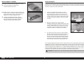
WARNING: Read the ENTIRE instruction manual to become familiar with the features of the product before
operating. Failure to operate the product correctly can result in damage to the product, personal property and
cause serious injury.
This is a sophisticated hobby product. It must be operated with caution and common sense and requires some basic
mechanical ability. Failure to operate this Product in a safe and responsible manner could result in injury or damage
to the product or other property. This product is not intended for use by children without direct adult supervision. Do
not attempt disassembly, use with incompatible components or augment product in any way without the approval
of Horizon Hobby, LLC. This manual contains instructions for safety, operation and maintenance. It is essential to
read and follow all the instructions and warnings in the manual, prior to assembly, setup or use, in order to operate
correctly and avoid damage or serious injury.
SAFE OPERATING RECOMMENDATIONS
• Inspect your model before every fl ight to ensure it is airworthy.
• Be aware of any other radio frequency user who may present an interference problem.
• Always be courteous and respectful of other users in your selected fl ight area.
• Choose an area clear of obstacles and large enough to safely accomodate your fl ying activity.
• Make sure this area is clear of friends and spectators prior to launching your aircraft.
• Be aware of other activities in the vicinity of your fl ight path that could cause potential confl ict.
• Carefully plan your fl ight path prior to launch.
• Abide by any and all established AMA National Model Aircraft Safety Code.
BEFORE STARTING ASSEMBLY
• Remove parts from bag.
• Inspect fuselage, wing panels, rudder and stabilizer for damage.
• If you fi nd damaged or missing parts, contact your place of purchase.
• Charge transmitter and receiver batteries.
• Center trims and sticks on your transmitter.
• For a computer radio, create a model memory for this particular model.
• Bind your transmitter and receiver, using your radio system’s instructions.
NOTICE: Rebind the radio system once all control throws are set. This will keep the servos from moving to their
endpoints until the transmitter and receiver connect. It will also guarantee the servo reversal settings are saved in the
radio system.
FAA INFORMATION
If you own this product, you may be required to register with the FAA.
For up-to-date information on how to register with the FAA, please visit https://registermyuas.faa.gov/.
For additional assistance on regulations and guidance on UAS usage, visit knowbeforeyoufl y.org/.

3 EN
Pitts S-2B 50–60cc
Part # Description
HAN239001 Stabilizer with Elevators
HAN239002 Rudder
HAN239003 Landing Gear
HAN239004 Tailwheel Assembly
HAN239005 Landing Gear Fairings
HAN239006 Hardware Set
HAN239007 Wing Tubes
HAN239008 Top Hatch & Canopy
HAN239009 Front Hatch
HAN239010 Cabane Strut Set
HAN239011 Interplane Strut Set
HAN239012 Fuselage
HAN239013 Cowling
HAN239014 Wheel Pants
HAN239015 Wing Set, Upper
HAN239016 Spinner 3
3
/
4
inch
HAN239017 Wing Set, Lower
HAN239019 Pushrod Set
HAN239020 Fuel Tank
HAN239021 Wheels
HAN239022 Upper Wing Center Section
HAN239023 Electric Motor Mount Set
HAN239024 Gas Engine Templates
REPLACEMENT PARTS
TABLE OF CONTENTS
Notice ......................................................................................................................................................................2
Meaning of Special Language ..................................................................................................................................2
Safety Warnings and Precautions .............................................................................................................................2
Safe Operating Recommendations ...........................................................................................................................2
Before Starting Assembly .........................................................................................................................................2
FAA Information .......................................................................................................................................................2
Replacement Parts ...................................................................................................................................................3
Required Adhesives .................................................................................................................................................3
Required for Completion - All Power Options ............................................................................................................4
Required for Completion - Gas Engine Installation ....................................................................................................4
Required for Completion - Electric Motor Installation ................................................................................................4
Optional Parts ..........................................................................................................................................................4
Tools Required .........................................................................................................................................................4
Removing Wrinkles ..................................................................................................................................................5
Building Precautions ................................................................................................................................................5
Transportation and Storage ......................................................................................................................................5
Replacement Covering .............................................................................................................................................5
Checking Blind Nuts.................................................................................................................................................5
Aileron Installation ...................................................................................................................................................5
Aileron Servo Installation .........................................................................................................................................6
Stabilizer Installation ................................................................................................................................................8
Receiver Installation ...............................................................................................................................................10
Rudder and Servo Linkage Installation ...................................................................................................................11
Tail Wheel Installation ............................................................................................................................................12
Elevator and Servo Linkage Installation ..................................................................................................................12
Landing Gear Installation .......................................................................................................................................14
Cabane Strut Installation ........................................................................................................................................15
Electric Motor Installation .......................................................................................................................................17
Spinner and Propeller Preparation ..........................................................................................................................18
Gas Engine Installation ...........................................................................................................................................19
Fuel Tank Assembly and Installation .......................................................................................................................20
Cowling Installation................................................................................................................................................21
Center of Gravity ....................................................................................................................................................22
Canopy Installation ................................................................................................................................................22
Control Throws ......................................................................................................................................................23
Prefl ight Checklist ..................................................................................................................................................23
Daily Flight Checks ................................................................................................................................................23
Limited Warranty ...................................................................................................................................................24
Warranty and Service Contact Information .............................................................................................................25
Instructions for Disposal of WEEE by Users in the European Union ..........................................................................25
Academy of Model Aeronautics National Model Aircraft Safety Code .......................................................................25
REQUIRED ADHESIVES
Description
15-minute epoxy
30-minute epoxy
Canopy Glue
Thin CA
Medium CA
Threadlock, low and high strength

4EN
REQUIRED FOR COMPLETION - ALL POWER OPTIONS
REQUIRED FOR COMPLETION - GAS ENGINE INSTALLATION
REQUIRED FOR COMPLETION - ELECTRIC MOTOR INSTALLATION
# Required Part # Description
7 SPMSA6380 A6380 H-T/H-S Digital HV Servo
1 SPMA3002 Heavy-Duty Servo Extension 9-inch
1 SPMA3006 Heavy-Duty Servo Extension 36-inch
4 SPMA3051 Standard Servo Extension 6-inch
1 SPMA3058 Standard Y-Harness
1 SPMAR12310T AR12310T 12CH PowerSafe Telemetry Receiver
1 SPMB4000LPRX 4000mAh 2S 7.4V LiPo Rx Battery
# Required Part # Description
1 DLEG0060 DLE-60cc Twin Gas Engine with Electronic Ignition
1 SPMSA6380 A6380 H-T/H-S Digital HV Servo
1 DUB800 Tygon Gas Tubing, 3-feet Large
1 EVOA112 Evolution 3 Wire Ignition/RX Switch
2 HAN116 Fuel Filler with T and Overfl ow Fitting
1 SPMB4000LPRX 4000mAh 2S 7.4V LiPo Rx Battery
# Required Part # Description
1 GPMG4800 Rimfi re 50cc Electric Motor
1 CSE010010300 Edge 160HV 50V ESC 010-0103-00
1 CSE010000401 CC BEC PRO 20A Max 12S swtch reg
2 SPMX70006S30 7000mah 6S 22.2V Smart 30C; IC5
# Required Part # Description
1 DLEG0061 DLE-61cc Gas Engine w/Elec Ignition
1 EVOA100 Optical Ignition Kill Switch
1 HAN239025 Sport Pilot Figure:Pitts S2B
1 SPMAS3000 AS3000 AS3X Stabilization Module
TOOLS REQUIRED
Description
Adjustable wrench
Balancing stand
Box Wrench Set
Clamps
Crimping tool
Drill and tap set, metric
Drill bit set, Imperial or Metric
Epoxy brushes
Felt-tipped pen
Hemostats
Hex wrench set, Imperial and Metric
Hobby knife with #11 blade
Hobby scissors
Hook and loop straps
Hook and loop tape
Isopropyl alcohol
Light machine oil
Low-tack tape
Mixing sticks
Needle nose pliers
Nut driver set, Imperial and Metric
Paper towels
Pencil
Petroleum jelly
Phillips screwdriver: #1, #2
Pin vise
Rotary tool
Ruler
Sanding bar
Sanding drum for rotary tool
Sandpaper
Scissors
Side cutters
Square
Tap handle
Tapered reamer
Tie wraps
Toothpicks
Wire stripper
OPTIONAL PARTS

5 EN
Pitts S-2B 50–60cc
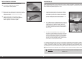
REMOVING WRINKLES
The covering of your model may develop wrinkles during shipping. Use a covering iron (HAN101) with a sealing iron
sock (HAN141) to remove them. Start with a lower heat setting and use caution while working around areas where the
colors overlap to prevent separating the colors. It is also advised to use caution around the clear windows and wing
tips as these items are plastic and could distort with excessive heat. Avoid using too much heat, which could also
separate the colors. Placing a cool damp cloth on adjacent colors will also help prevent the separation of the colors
while removing wrinkles. Only use a heat gun (HAN100) once the covering iron has been used.
BUILDING PRECAUTIONS
Prepare the work surface prior to beginning the build. The surface should be soft and free of any sharp objects. We
recommend resting the airframe parts on a soft towel or pit mat to prevent scratching or denting the surface of the
aircraft.
TRANSPORTATION AND STORAGE
When transporting and storing your model, you will need a minimum of 80 inches (2m) in length, and 26 inches
(65cm) in height to accommodate the size of the fuselage. We also recommend the use of wing and stabilizer bags to
help protect these surfaces during transport and storage. The control horns and linkages can cause damage to other
surfaces even when placed in storage bags. Always transport and store the wings and stabilizer so the linkages do not
contact other panels to prevent damage.
REPLACEMENT COVERING
Your model is covered with UltraCote® fi lm in the following colors. If repairs are required, order these coverings to
make those repairs.
HANU866 True Red
HANU870 White
HANU874 Black
CHECKING BLIND NUTS
When building the aircraft, you will be required to thread machine screws into blind nuts. We recommend pre-threading
the screws to make sure the blind nuts are clear of any debris. If the screws do not thread in easily, clear the threads
using the appropriate tap and tap handle.
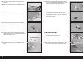
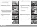
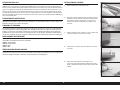
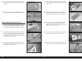
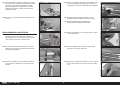
AILERON INSTALLATION
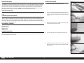
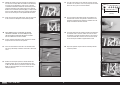
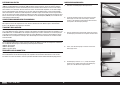
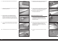
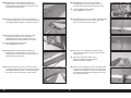
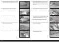
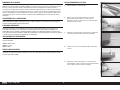
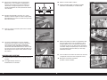
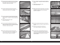
1. Separate the aileron and hinges from the wing.
2. Apply a small amount of petroleum jelly to the fl ex point of
each hinge. Flex the hinge to work the petroleum jelly into the
hinge. This will help in preventing the epoxy from getting into
the hinge.
3. Check the fi t of the hinge in the aileron. The pin in the hinge
will align with the bevel of the aileron.
4. Check that the hinges are perpendicular to the hinge axis.
5. Remove the hinge. Mix 1/4 ounce (7.5cc) of 30-minute epoxy.
Apply the epoxy to the end of each hinge that will be placed
into the aileron.

6EN
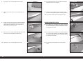
6. Apply epoxy in each of the hinge pockets in the aileron.
7. Fit the hinges into the aileron. Check the alignment of each
hinge.
8. Remove any excess epoxy using a paper towel and isopropyl
alcohol. Check the hinge positions to make sure they were
not disturbed when removing the excess epoxy. Allow the
epoxy to fully cure before proceeding.
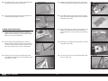
9. Mix 1/4 ounce (7.5cc) of 30-minute epoxy. Apply epoxy to the
end of each hinge that will be placed into the wing.
10. Apply epoxy in each of the hinge pockets in the wing.
11. Fit the aileron to the wing. Use a paper towel and isopropyl
alcohol to remove any excess epoxy.
12. Use low-tack tape to hold the aileron in position until the
epoxy fully cures. Allow the epoxy to cure before proceeding.
The remaining aileron hinges can be glued at this time.
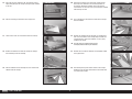
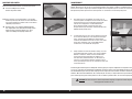
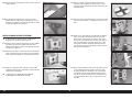
AILERON SERVO INSTALLATION
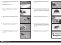
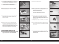
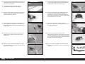
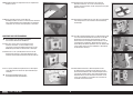
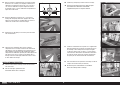
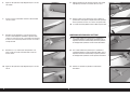
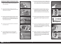
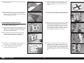
13. Use a fi nger to locate the position for the aileron control horns
on the underside of the aileron. Use a hobby knife to remove
the covering to expose the control horn mounting location on
the underside of the aileron.
14. Use a fi nger to locate the position for the aileron control horns
on the upper side of the aileron. Use a hobby knife to remove
the covering to expose the control horn mounting location on
the upper side of the aileron..
15. Fit the control horn into position on the underside of the
aileron.

7 EN
Pitts S-2B 50–60cc
1 inch
(25mm)
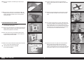
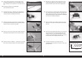
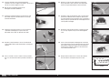
16. Secure the control horn using the control horn backplate and
an M3 x 14 socket head cap screw. Use a 2.5mm hex wrench
to tighten the screw.
Do not overtighten the screw and damage
the underlying structure.
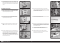
21. Place 2-3 drops of thin CA in each of the holes to harden
the surrounding wood. Allow the CA to fully cure before
proceeding.
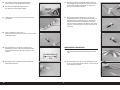
17. Install the rubber grommets and eyelets in the aileron servos.
Use the instructions included with the servo for correct
installation.
22. Place the servo on the servo cover. The output of the servo
faces the leading edge (tape) of the cover. With a small gap
between the cover and servo, use a felt-tipped pen to mark
the locations of the servo mounting screws on the mounting
tabs.
18. Use a drill and 1.5mm drill bit to drill the four mounting holes
for the aileron servo covers. Use the holes in the cover as a
guide.
23. Remove the servo from the cover. Use a drill and 1.5mm drill
bit to drill the holes for the servo mounting screws.
19. Remove the cover from the wing. Leave the tape toward the
leading edge as a reference for the following steps.
24. Secure the servo to the mounting tabs using the screws
provided with the servo. Center the servo and place the arm
on the servo perpendicular to the servo centerline. Remove
any unused arms so they won’t interfere with the operation
of the servo.
20. Use a #1 Phillips screwdriver to thread an M2 x 8 sheet metal
screw into each of the holes. Remove the screws before
proceeding.
25. Enlarge the hole in the arm that is 1 inch (25mm) from the
center of the arm using a pin vise and 3mm drill bit.

8EN
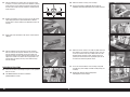
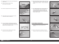
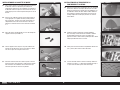
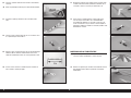
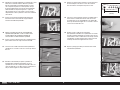
26. Secure a 9-inch (230mm) to the servo lead using a safety
connector.
Use a 6-inch (150mm) extension for the bottom wing servo.
31. Remove the tape from the wing and aileron. Secure one of
the rod ends to the outer hole of the control horn using a #2
Phillips screwdriver and an M3 x 10 machine screw.
28. Secure the servo and cover to the wing using a #1 Phillips
screwdriver and four M2 x 8 sheet metal screws.
27. Route the extension through the wing and out the wing root. 32. Attach the remaining rod end to the servo arm using an M3
x 10 machine screw, M3 washer and M3 lock nut. Use a
#2 Phillips screwdriver and 5mm nut driver to tighten the
hardware. Adjust the linkage to center the aileron when the
aileron servo is centered.
29. Thread the plastic rod ends on the 60mm threaded aileron
pushrod. Thread each of the rod ends equally on the threaded
rod. Start with a length of 87mm.
30. Snap the ball into the rod end. Prepare both rod ends at this
time.
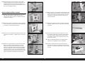
STABILIZER INSTALLATION
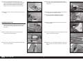
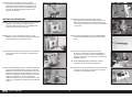
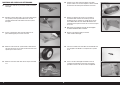
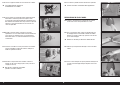
33. Separate the elevators from the stabilizer. Remove the hinges
and set the elevators and hinges aside.
34. Use a hobby knife to remove the covering at the rear of the
fuselage under the fi n, exposing the slot for the stabilizer.

9 EN
Pitts S-2B 50–60cc
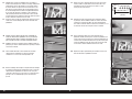
35. Place low-tack tape around the slot. This will help prevent
epoxy from getting on the fuselage when gluing the stabilizer
in the slot.
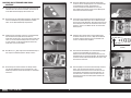
36. Slide the retaining pins forward on the canopy hatch.
37. Lift the hatch at the rear and remove it from the fuselage.
38. Remove the forward hatch from the fuselage by sliding it
back and lifting it from the fuselage.
39. Slide the stabilizer into the slot. Align the rear section of the
stabilizer with the fuselage.
40. Measure back from the rear edge of the canopy opening
to the tips of the stabilizer on the left and right sides of
the fuselage. Position the stabilizer so the right and left
measurements are the same. Use T-pins to keep the stabilizer
from moving in the slot.
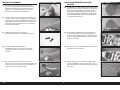
41. Use a felt-tipped pen to transfer the outline of the fuselage
onto the stabilizer.
42. Remove the stabilizer from the fuselage. Use a hobby knife
with a new #11 blade to and a straight edge to remove the
covering from the center of the stabilizer 1/8 inch (3mm)
inside the lines drawn.
Use light pressure to avoid cutting into the
underlying wood, weakening the stabilizer.
43. Remove the lines from the stabilizer using isopropyl alcohol
and a paper towel.
44. Slide the longer wing tube into the socket in the fuselage.
Position the tube so equal amounts of the tube extend from
each side of the fuselage.

10EN
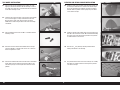
AA
A=A
45. Slide the stabilizer back into the slot in the fuselage. Stand
8-10 feet (2-3 meters) and check that the stabilizer is parallel
to the wing tube. If not, remove the stabilizer and lightly sand
the slot in the fuselage until the stabilizer is aligned perfectly
to the wing tube.
46. Remove the stabilizer and mix 1/2 ounce (15cc) of 30-minute
epoxy. Apply epoxy to the exposed wood on the stabilizer
that will come in contact with the bare wood of the slot in the
fuselage.
47. Apply epoxy to the slot where it will come in contact with the
stabilizer.
48. Slide the stabilizer into the slot and check the alignment
with the fuselage and wing tube. Remove any excess epoxy
from the stabilizer and fuselage using a paper towel and
isopropyl alcohol. Check the alignment of the stabilizer as the
epoxy cures to make sure it does not change position in the
fuselage. Once the epoxy has fully cured, remove the tape
from the fuselage.
RECEIVER INSTALLATION
49. Secure the receiver in the fuselage using the screws provided
with the receiver.
For additional details, refer to the instructions
provided with the receiver.
50. Mount the remote receiver(s) in the fuselage.
Use the instructions included with your receiver for
additional installation information for the remote receivers.
51. Mount the receiver switch in the radio tray. Holes will need
to be drilled in the tray for the mounting screws. It may be
necessary to trim the tray using a hobby knife with a #11
blade to properly install the switch. Connect two 6-inch
(150mm) servo extensions to the appropriate ports on the
receiver for the lower wing aileron servos.
52. Secure the receiver batteries in the fuselage using hook
and loop tape (not included) and hook and loop straps (not
included).
Do not cover warnings on the battery when
mounting them in the fuselage.

11 EN
Pitts S-2B 50–60cc
1 inch
(25mm)
RUDDER AND SERVO LINKAGE INSTALLATION
53. Install the hinges in the rudder using 30-minute epoxy. Use
the techniques outlined in the section for the aileron hinges.
54. Secure the rudder to the fi n. Use low-tack tape to hold the
rudder in position until the epoxy fully cures.
55. Remove the covering from the rudder to expose the control
horn mount. Secure the rudder control horn using an M3 x
25 socket head cap screw and 2.5mm hex wrench. Make
sure not to overtighten the screw and damage the underlying
structure of the rudder.
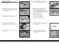
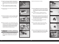
57. The pushrod will exit at the rear of the fuselage. Use a hobby
knife with a #11 blade to trim the covering so the pushrod
can exit the fuselage.
58. Snap an aluminum ball into the plastic rod end, then thread
the rod end 14 turns on the pushrod. Secure the rod end to
the outer hole of the rudder control horn using a #2 Phillips
screwdriver and an M3 x 10 machine screw.
59. Mount the rudder servo in the fuselage. The holes for the
servo will require drilling and preparing using thin CA. Center
the rudder servo using the radio system. Place the servo arm
on the rudder so it is 90-degrees to the rudder pushrod.
60. Use side cutters to trim excess from the servo arm. Enlarge
the hole in the arm that is 1 inch (25mm) from the center of
the arm using a pin vise and 3mm drill bit.
61. Snap an aluminum ball into the plastic rod end. Attach the
rod end to the servo arm using an M3 x 10 machine screw,
M3 washer and M3 locknut. Tighten the hardware with a #2
Phillips screwdriver and 5mm nut driver.
56. Slide the 23
1
/
4
inch (590mm) rudder pushrod into the rudder
pushrod tube in the fuselage.
62. Thread the rod end on the rudder pushrod. Check that when
the rudder servo is centered, and the arm is on the servo, the
rudder is centered. Thread the rod end as necessary to center
the rudder. Once centered, secure the servo arm to the servo
using the hardware supplied with the servo.

12EN
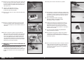
TAIL WHEEL INSTALLATION
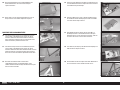
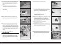
63. Place the tiller arm on the bottom of the rudder. Use a felt-
tipped pen to mark the locations for the mounting screws on
the rudder. Use a drill and 1.5mm drill bit to drill the two holes
for the tiller mounting screws.
64. Thread an M3 x 10 sheet metal screw into each hole. Remove
the screws and apply 2-3 drops of thin CA into each hole.
Once the CA has fully cured, attach the tiller arm to the
bottom of the rudder using the two screws and a #2 Phillips
screwdriver.
65. Place the M4 lock washers on the M4 x 15 tailwheel bracket
mounting screws.
66. Attach the tail wheel bracket to the bottom of the fuselage
using the two M4 x 15 socket head screws. Use a 3mm hex
wrench to tighten the screws.
67. Connect the tailwheel tiller arm to the tiller arm on the bottom
of the rudder using the two springs. Bend the loops on the
ends of the springs as necessary to attach and secure their
position.
ELEVATOR AND SERVO LINKAGE INSTALLATION
68. Install the hinges in the elevator using 30-minute epoxy. Use
the techniques outlined in the section for the aileron hinges.
Secure the elevators to the stabilizer. Use low-tack tape to
hold the rudder in position until the epoxy fully cures. Once
cured, remove the tape.
69. Install the elevator servo support brace in the fuselage using
three M3 x 10 sheet metal screws. We recommend threading
the screws in the tray and preparing the holes using thin CA
as outlined earlier in this manual.
70. Slide the 19
1
/
16
inch (485mm) elevator pushrod into the
rudder pushrod tube in the fuselage.
71. The pushrod will exit at the rear of the fuselage. Use a hobby
knife with a #11 blade to trim the covering so the pushrod
can exit the fuselage.

13 EN
Pitts S-2B 50–60cc
13/16 inch
(21mm)
72. Position the elevator servo in the tray with the output facing
the rear of the fuselage. Mark the locations for the mounting
screws on the tray. Remove the servo and use a drill and
1.5mm drill bit to drill the locations for the mounting screws
Thread the mounting screws into the holes in the radio tray.
Remove the screws before proceeding Apply 2-3 drops of thin
CA in each hole. Allow the CA to fully cure before proceeding
Secure the servo using the screws provided with the servo.
Please follow the steps as outlined for the elevator
control horn installation. The screw holding the right
side rod end to the control horn will not be accessible
once the control horn has been installed.
74. Snap an aluminum ball into the plastic rod end, then thread
the plastic rod end 14 turns on the pushrod.
77. Use side cutters to trim excess from the servo arm. Enlarge
the hole in the arm that is 13/16 inch (21mm) from the center
of the arm using a pin vise and 3mm drill bit.
78. Snap an aluminum ball into the plastic rod end. Attach the
rod end to the servo arm using an M3 x 10 machine screw,
M3 washer and M3 locknut. Tighten the hardware with a #2
Phillips screwdriver and 5mm nut driver.
79. Thread the rod end on the elevator pushrod. Check that when
the elevator servo is centered, and the arm is on the servo,
the elevator is centered. Thread the rod end as necessary to
center the elevator. Once centered, secure the servo arm to
the servo using the hardware supplied with the servo.
80. Repeat the previous steps to install the remaining elevator
servo and pushrod.
75. Secure the rod end to the outer hole in the elevator control
horn using a #2 Phillips screwdriver and an M3 x 10 machine
screw.
76. Remove the covering to expose the elevator control horn
mounting location. Secure the elevator control horn using
an M3 x 20 socket head cap screw and 2.5mm hex wrench.
Make sure not to overtighten the screw and damage the
underlying structure.
73. Center the servo using the radio system. Place the servo arm
on the servo so it is 90-degrees to the elevator pushrod.

14EN
LANDING GEAR INSTALLATION
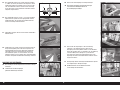
81. Use two 1/2-inch wrenches to attach the axle to the landing
gear
82. Remove the wheel collars and use a fl at fi le to make a fl at
area along the bottom of the axle. The setscrews from the
wheel collars will be tightened onto this fl at area.
84. Fit the wheel to the axle, then install the remaining wheel
collar on the axle. Make sure the setscrews are tightened on
the fl at area made on the axle.
86. Check that the wheel can rotate freely without binding on the
wheel collars or wheel pant. Adjust the wheel collars until the
wheel can rotate freely on the axle.
87. Use a hobby knife and #11 blade to remove the covering on
the landing gear fairings for the mounting screws. Attach the
landing gear fairing to the landing gear using two M4 x 10
button head screws and two M4 washers. Use thread lock on
the screws before tightening them with a 2.5mm hex wrench.
Do not overtighten the screws and damage
the underlying structure of the fairings.
Repeat the previous steps to assemble the
remaining landing gear assembly.
83. Slide one wheel collar on the axle. Apply a drop of light
machine oil on the axle.
88. Slide an M4 lock washer and M4 washer on the M4 x 25
socket head cap screws. Prepare all four screws.
89. Attach the landing gear to the fuselage using the M4 x 25
socket head cap screws prepared in the previous step.
Tighten the screws using an M3 hex wrench.
85. Mount the wheel pant on the landing gear using two M3 x 12
sheet metal screws.

15 EN
Pitts S-2B 50–60cc
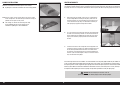
90. The landing gear cover can be installed on the bottom of the
fuselage using contact adhesive or clear tape.
91. Check that the landing gear fairings do not rub against the
fuselage. Adjust their position if necessary.
93. Slide an M4 lock washer and M4 washer on an M4 x 15
button head screw. Prepare four of these screws. Attach the
rear cabane strut and cabane strut brace using these screws.
Leave the screws loose so the cabane can be positioned.
95. Remove the hatch from the top wing center section using a
#2 Phillips screwdriver. Set the two screws and cover aside.
97. Attach the top wing center section to the cabane struts using
two M4 x 15 button head screw. Use thread lock on the
screws. Tighten all the screws at this time using a 3mm hex
wrench.
98. Route two 36-inch (920mm) servo leads from the receiver to
the top wing center section.
94. Attach the cabane strut brace to the forward cabane strut
using two M4 x 10 button head screws and two M4 nuts. Use
thread lock on the screws.
99. Use clear or red tape to secure the servo leads to the inside
of the rear cabane strut.
96. Use a hobby knife with a #11 blade to remove the covering
for the servo leads and mounting screws in the underside of
the top wing center section.
CABANE STRUT INSTALLATION
92. Slide an M4 lock washer and M4 washer on an M4 x 15
button head screw. Prepare four of these screws. Attach the
forward cabane strut using these screws. Leave the screws
loose so the cabane can be positioned.

16EN
100. Attach the interplane strut mounting tabs to the bottom of
the top wing using M4 x 10 button head screws. Leave the
screws loose so the tabs can be positioned correctly.
101. Slide the shorter wing tube into the socket in the top wing.
The tube will easily slide into position. If not, use 0000 steel
wool to polish the wing tube.
102. Slide the tube into the top wing center section. Secure the
wing panel using two 1/4-20 x 1 inch nylon wing mounting
bolts. Connect the servo lead from the wing to the extension.
Always install all the nylon bolts to secure the wing panels.
103. Attach the interplane strut mounting tabs to the top of the
bottom wing using M4 x 10 button head screws. Leave the
screws loose so the tabs can be positioned correctly.
104. Slide the longer wing tube into the socket in the bottom
wing. The tube will easily slide into position. If not, use 0000
steel wool to polish the wing tube. Slide the bottom wing into
position on the fuselage.
105. Secure the wing panel using two 1/4-20 x 1 inch nylon wing
mounting bolts. Connect the servo lead from the wing to the
extension.
Always install all the nylon bolts to secure the wing panels.
106. Fit the interplane struts to the tabs. Use the strut mounting
pins to help hold the strut in place. The tabs will require
bending to align with the strut.
107. Remove the tabs from the wing panels and use two pliers to
bend the tabs slightly so they align with the struts.
Do not bend the tabs while attached to the wing.
This could damage the structure of the wing.
108. Once bent, the tabs should align with the struts. The strut
mounting pins should slide easily through the interplane
strut and into the tab. Use thread lock on the screws when
installing the mounting tabs.

17 EN
Pitts S-2B 50–60cc
109. Secure the interplane strut mounting pins using the clips
provided.
ELECTRIC MOTOR INSTALLATION
If installing a gas engine, please skip to
the next section of the manual
111. Use the lines around the holes in the fi rewall and template to
properly align the template. Use low-tack tape to secure the
motor mounting template on the fi rewall.
112. Use a drill and 1/4-inch (6.5mm) drill bit to drill the holes
in the fi rewall for the motor mounting screws. Remove the
template and tape from the fi rewall.
114. Layer the mounts and use low-tack tape to hold them
together until the epoxy fully cures. Make sure all the holes
are aligned.
115. Remove the forward compartment cover from the fuselage
using a #2 Phillips screwdriver. Set the screws and cover
aside.
113. Mix 3/4 ounce (20cc) of 30-minute epoxy. Apply the epoxy to
the face of three of the plywood EP mounts.
The EP firewall is four pieces of plywood
that are laminated together.
116. Use an M5 x 60 socket head cap screw, an M5 washer and
an aluminum standoff to draw the M5 blind nut into the back
of the fi rewall. Tighten the screw using an M4 hex wrench.
Install all four blind nuts. Secure the blind nuts to the inside of
the fi rewall using a small amount of 30-minute epoxy. Make
sure no epoxy enters the threads of the blind nuts.
117. Remove the tape once the epoxy cures on the EP mounts.
Attach the mount to the fi rewall using four aluminum
standoffs, M5 x 60 socket head cap screws and four M5
washers. Use thread lock on the screws to prevent them from
vibrating loose. Tighten the screws using an M4 hex wrench.
110. Once all the pins have been secured, tighten the M4 x 10
button head screws using a 2.5mm hex wrench. Remember
to apply a drop of thread lock on each screw to prevent it
from vibrating loose.

18EN
118. Attach the mount to the motor using the screws provided with
the motor.
For additional details, refer to the
instructions provided with the motor.
119. Attach the motor to the motor mount using four aluminum
standoffs, four M5 x 60 socket head cap screws, four M5
blind nuts and four M5 washers. Use thread lock on the
screws to prevent them from vibrating loose. Tighten the
screws using an M4 hex wrench.
121. Install any connectors necessary for the battery and/or motor.
Secure the speed control to the fuselage. Connect the motor
to the speed control.
123. Slide the forward hatch back into position.
Skip to the section “Cowling Installation.”
SPINNER AND PROPELLER PREPARATION
124. Trim the spinner cone to fi t the propeller. There should be
1/16 inch (1.5mm) clearance around the propeller.
126. Slide the spinner backplate and propeller on the engine shaft.
127. Attach the spinner cone to the spinner backplate using one
of the spinner mounting screws. Adjust the propeller in the
openings.
122. Replace the forward compartment cover. Install the batteries
using hook and loop tape (not included) and hook and loop
straps (not included).
Do not cover warnings on the battery when
mounting them in the fuselage.
125. Use a felt-tipped pen to mark the location for the propeller
mounting screws using the washer from the engine. Use a
drill press to drill the holes in the propeller for the mounting
screws.
Use a reamer to align the washer with the propeller.
120. When installing the motor, the distance from the fi rewall
to the face of the drive washer will measure 6
1
/
2
inches
(165mm). It may be necessary to use different standoffs
when using motors other than those recommended.

19 EN
Pitts S-2B 50–60cc
128. Carefully remove the spinner cone and use a drill bit to make
a small indentation on the backplate for the mounting screws.
Remove the propeller and backplate. Use a drill press to drill
the holes in the spinner backplate for the propeller mounting
screws.
GAS ENGINE INSTALLATION
129. Use the lines around the holes in the fi rewall and template to
properly align the template. Use low-tack tape to secure the
engine mounting template on the fi rewall.
130. Use a drill and 1/4-inch (6.5mm) drill bit to drill the holes
in the fi rewall for the engine mounting screws. Remove the
template and tape from the fi rewall.
131. Remove the forward compartment cover from the fuselage
using a #2 Phillips screwdriver. Set the screws and cover
aside.
133. Use the four M5 x 60 socket head cap screws, four M5
washers and four aluminum standoffs to attach the engine to
the fi rewall. Make sure to use thread lock on all the screws to
prevent them from vibrating loose.
134. Slide a silicone clevis retainer on the metal clevis. Thread the
clevis on the longer throttle pushrod.
135. Drill a hole in the fi rewall that aligns with the carburetor arm.
Slide the pushrod wire though the hole and into the fuselage,
Attach the clevis to the carburetor arm and slide the retainer
over the forks of the clevis.
Use the instructions included with the engine for details
regarding the installation of the carburetor arm.
136. Install the throttle servo in the throttle servo mount.
Center the servo and place the servo arm so the arms are
perpendicular to the servo centerline.
132. Use an M5 x 60 socket head cap screw, an M5 washer and
an aluminum standoff to draw the M5 blind nut into the back
of the fi rewall. Tighten the screw using an M4 hex wrench.
Install all four blind nuts. Remove the standoffs and screws.
Secure the blind nuts to the inside of the fi rewall using a
small amount of 30-minute epoxy. Make sure no epoxy enters
the threads of the blind nuts.

20EN
137. Use side cutters to remove the arms that face up, forward
and rearward. Install the pushrod connector in the servo arm.
Use a toothpick to apply a drop of thin CA to secure the nut.
Use the instructions included with the engine for details
regarding the position of the pushrod connector.
138. Secure the servo arm to the servo using the hardware
included with the servo.
142. Slide the fuel tubing into position.
139. Use 30-minute epoxy to glue the servo tray in the fuselage.
Allow the epoxy to fully cure before sliding the pushrod
through the connector.
140. Close the carburetor and use the radio system to move
the servo to the close position. Secure the pushrod in the
connector using the M3 setscrew and 2mm hex wrench.
Apply thread lock on the setscrew to prevent it from vibrating
loose. Check the operation of the carburetor to make so it
opens and closes as outlined in the engine instructions.
FUEL TANK ASSEMBLY AND INSTALLATION
141. Carefully heat the tubes on the inside of the stopper assembly
to have a slight barb, similar to that on the front of the
stopper. Bend one tube so if will face toward the top of the
tank when installed.
144. Install the stopper in the tank. Make sure the clunk(s) can
move freely inside the tank. Reposition the tubes in the
stopper or trim the fuel tubing if necessary. Tighten the screw
in the stopper using a #2 Phillips screwdriver secure the
stopper in the tank.
Overtightening the stopper can potentially split the fuel tank.
145. Secure fuel tubing to the outside of the tank using tie wraps.
Trim the tie wraps so they don’t interfere with the installation
of the fuel tank.
146. Secure the fuel tank in the fuselage using hook and loop
straps. Use a piece of thin foam rubber between the tank
and fuel tank tray to prevent it from sliding on the tray during
extreme maneuvers.
143. Attach the clunk to the fuel line. The distance from the rear
aluminum plate to the end of the stopper will be 5
1
/
2
inches
(140mm). Use a small piece of wire to secure the tubing so it
does not slide off the tube or clunk.
We recommend using a filtered clunk for the
engine, and a second clunk to fuel the aircraft.
La pagina si sta caricando...
La pagina si sta caricando...
La pagina si sta caricando...
La pagina si sta caricando...
La pagina si sta caricando...
La pagina si sta caricando...
La pagina si sta caricando...
La pagina si sta caricando...
La pagina si sta caricando...
La pagina si sta caricando...
La pagina si sta caricando...
La pagina si sta caricando...
La pagina si sta caricando...
La pagina si sta caricando...
La pagina si sta caricando...
La pagina si sta caricando...
La pagina si sta caricando...
La pagina si sta caricando...
La pagina si sta caricando...
La pagina si sta caricando...
La pagina si sta caricando...
La pagina si sta caricando...
La pagina si sta caricando...
La pagina si sta caricando...
La pagina si sta caricando...
La pagina si sta caricando...
La pagina si sta caricando...
La pagina si sta caricando...
La pagina si sta caricando...
La pagina si sta caricando...
La pagina si sta caricando...
La pagina si sta caricando...
La pagina si sta caricando...
La pagina si sta caricando...
La pagina si sta caricando...
La pagina si sta caricando...
La pagina si sta caricando...
La pagina si sta caricando...
La pagina si sta caricando...
La pagina si sta caricando...
La pagina si sta caricando...
La pagina si sta caricando...
La pagina si sta caricando...
La pagina si sta caricando...
La pagina si sta caricando...
La pagina si sta caricando...
La pagina si sta caricando...
La pagina si sta caricando...
La pagina si sta caricando...
La pagina si sta caricando...
La pagina si sta caricando...
La pagina si sta caricando...
La pagina si sta caricando...
La pagina si sta caricando...
La pagina si sta caricando...
La pagina si sta caricando...
La pagina si sta caricando...
La pagina si sta caricando...
La pagina si sta caricando...
La pagina si sta caricando...
La pagina si sta caricando...
La pagina si sta caricando...
La pagina si sta caricando...
La pagina si sta caricando...
La pagina si sta caricando...
La pagina si sta caricando...
La pagina si sta caricando...
La pagina si sta caricando...
La pagina si sta caricando...
La pagina si sta caricando...
La pagina si sta caricando...
La pagina si sta caricando...
La pagina si sta caricando...
La pagina si sta caricando...
La pagina si sta caricando...
La pagina si sta caricando...
-
 1
1
-
 2
2
-
 3
3
-
 4
4
-
 5
5
-
 6
6
-
 7
7
-
 8
8
-
 9
9
-
 10
10
-
 11
11
-
 12
12
-
 13
13
-
 14
14
-
 15
15
-
 16
16
-
 17
17
-
 18
18
-
 19
19
-
 20
20
-
 21
21
-
 22
22
-
 23
23
-
 24
24
-
 25
25
-
 26
26
-
 27
27
-
 28
28
-
 29
29
-
 30
30
-
 31
31
-
 32
32
-
 33
33
-
 34
34
-
 35
35
-
 36
36
-
 37
37
-
 38
38
-
 39
39
-
 40
40
-
 41
41
-
 42
42
-
 43
43
-
 44
44
-
 45
45
-
 46
46
-
 47
47
-
 48
48
-
 49
49
-
 50
50
-
 51
51
-
 52
52
-
 53
53
-
 54
54
-
 55
55
-
 56
56
-
 57
57
-
 58
58
-
 59
59
-
 60
60
-
 61
61
-
 62
62
-
 63
63
-
 64
64
-
 65
65
-
 66
66
-
 67
67
-
 68
68
-
 69
69
-
 70
70
-
 71
71
-
 72
72
-
 73
73
-
 74
74
-
 75
75
-
 76
76
-
 77
77
-
 78
78
-
 79
79
-
 80
80
-
 81
81
-
 82
82
-
 83
83
-
 84
84
-
 85
85
-
 86
86
-
 87
87
-
 88
88
-
 89
89
-
 90
90
-
 91
91
-
 92
92
-
 93
93
-
 94
94
-
 95
95
-
 96
96


Hangar 9 HAN2390 Manuale del proprietario
- Categoria
- Giocattoli telecomandati
- Tipo
- Manuale del proprietario
- Questo manuale è adatto anche per
in altre lingue
- English: Hangar 9 HAN2390 Owner's manual
- français: Hangar 9 HAN2390 Le manuel du propriétaire
- Deutsch: Hangar 9 HAN2390 Bedienungsanleitung
Documenti correlati
-
 Hangar 9 HAN5260 Manuale del proprietario
-
 Hangar 9 HANGAR 9 Ultra Stick 30cc Manuale del proprietario
-
 Hangar 9 HAN5065 Manuale del proprietario
-
 Hangar 9 HAN2530 Manuale del proprietario
-
 Hangar 9 HAN4885 Manuale del proprietario
-
Evolution 33cc Manuale del proprietario
-
 Hangar 9 HAN2890 Manuale del proprietario
-
 Hangar 9 HAN4720CR Manuale del proprietario
-
 Hangar 9 HAN5260B Manuale del proprietario


