CARLO GAVAZZI SD2DUG24 Guida d'installazione
- Tipo
- Guida d'installazione

SD2DUG24
Instruction Manual
Manuel d'instructions
Manual de instrucciones
Manuale di istruzioni
MANUAL SD2DUG24 code 8021740 / 060718 http://www.carlogavazzi.com/ CARLO GAVAZZI
ENGLISH
Read carefully the instruction manual. If the instrument
is used in a manner not specified by the producer, the
protection provided by the instrument may be impaired.
Maintenance: make sure that the connections are correctly
carried out in order to avoid any malfunctioning or damage
to the instrument.
PRODUCT DESCRIPTION
COMMUNICATION PARAMETERS AND DUPLINE CHANNEL
PROGRAMMING
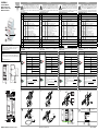
Part Description
A
Dupline
®
bus
B
Indication LEDs:
Green
(ON)
ON
OFF
1 blink
2 blinks
Power ON
Power OFF
Power supply not OK (<12V)
POW and D+ are short circuited
Yellow
(Dupline
bus)
ON
OFF
1 blink
2 blinks
3 blinks
4 blinks
5 blinks
6 blinks
Communication OK on the Dupline bus
No cummunication is present on the Dupline bus
Dupline bus is short circuited
Dupline input voltage error (D- wire is not connected)
Dupline output voltage error
Dupline bus overloaded
Dupline bus overload warning
Dupline (D+ and D-) wires are inverted
Yellow
(RS485)
ON
Short blink
Long blink
Communication OK on the RS485 bus
No communication is present on the RS485 bus (Timeout)
Modbus frame error or wrong address
C
Micro-USB port for connection to the USB port of the PC for programming
D
RS485 port terminals for Modbus RTU communication
E RS485 bus termination
F Power supply connection block
FRANÇAIS
Lire attentivement le manuel de l’utilisateur. Si l’appareil
est utilisé dans des conditions différentes de celles spécifiées
par le fabricant, le niveau de protection prévu par l’instrument
peut être compromis. Entretien: s’assurer que les connexions
sont réalisées correctement dans le but d’éviter toutes fautes
ou endommagements de l’appareil.
DESCRIPTION DU PRODUIT
PARAMÈTRES DE COMMUNICATION ET PROGRAMMATION DU
CANAL DUPLINE
ESPAÑOL
Lea atentamente este manual de instrucciones. Si el
equipo se utiliza de forma no especificada por el fabricante,
la protección dotada al equipo puede resultar dañada.
Mantenimiento: Asegúrese de que las conexiones relevantes
se hayan llevado a cabo correctamente, con el fin de evitar un
funcionamiento incorrecto o que el equipo resulte dañado.
DESCRIPCIÓN DEL PRODUCTO
PARÁMETROS DE COMUNICACIÓN Y PROGRAMACIÓN DE LOS
CANALES DUPLINE
ITALIANO
Leggere attentamente il manuale di istruzioni. Qualora
l’apparecchio venisse usato in un modo non specificato dal
costruttore, la protezione prevista dall’apparecchio potrebbe
essere compromessa. Manutenzione: Assicurarsi che le
connessioni previste siano eseguite correttamente al fine di
evitare qualsiasi malfunzionamento o danneggiamento dello strumento.
DESCRIZIONE DEL PRODOTTO
PARAMETRI DI COMUNICAZIONE E PROGRAMMAZIONE DEL
CANALE DUPLINE
D
F
C
B
B
E
A
Approvals: CE, cULus according to UL60950.
UL notes:
• This product is intended to be supplied by a Listed Information Tech-
nology Equipment AC Adaptor marked NEC Class 2 or LPS.
• Max ambient temperature: 40°C
Homologations: CE, cULus selon UL60950.
Notes UL:
• Ce produit est conçu pour être alimenté par un adaptateur secteur
Listés comme équipements de technologie de l'information NEC Classe
2 ou LPS.
• Température ambiante maxi: 40°C
!"#$
%!&#'
$($
$($
-20°C to +50°C
(-4°F to 122°F)
-50°C to +85°C
(-58°F to 185°F)
5a
5b
PC is not required
Factory settings
The SD2DUG24 can be directly powered and connected
without any programming, using the default parameters:
PC is required The SD2DUG24 parameters can be changed
Connect the SD2DUG24 to the PC to change the com-
munication parameters, using one of the following ports:
• The Micro-USB port using a standard USB cable* (4
and 5a figures)
• The RS485 port terminals on the bottom of the module
using an RS485 to USB converter* (5b figure)
*Not induded
Download the SD2DUG24 Software from www.productselection.net
Parameter Default value
Modbus address 1
Baud rate 9600
Data bits 8
Parity NONE
Stop bit 1
Number of Dupline
channels
128 channels
Outputs repeat inputs
Partie Description
A
Bus Dupline
®
B
LED d’informations:
Verte
(ON)
ON
OFF
1 clignot.
2 clignot.
Alimentation ON
Alimentation OFF
L'alimentation n'est pas correcte (<12V)
POW et D + sont en court-circuit
Jaune
(bus
Dupline)
ON
OFF
1 clignot.
2 clignot.
3 clignot.
4 clignot.
5 clignot.
6 clignot.
Communication sur le bus Dupline correcte
Pas de communication sur le bus Dupline
Bus Dupline est en court-circuit
Erreur de tension d'entrée sur le bus Dupline (le
câble D- n'est pas connecté)
Erreur
de tension de sortie sur le bus Dupline
Bus Dupline surchargé
Alerte de surcharge du bus Dupline
Câbles Dupline (D+ et D-) inversés
Jaune
(RS485)
ON
Clign. court
Clign. long
Communication sur le bus RS485 correcte
Pas de communication sur le bus RS485 (Timeout)
Erreur dans la trame Modbus ou adresse erronée
C
Port micro-USB pour se connecter au port USB de l'ordinateur pour la programmation
D
Bornes du port RS485 pour communication Modbus RTU
E Terminaison du bus RS485
F Bornes d’alimentation
Le PC n'est pas requis
Réglages d'usine
Le SD2DUG24 peut être alimenté directement et connecté
sans aucune programmation, en utilisant les paramètres
préréglés:
Le PC est requis Les paramètres de SD2DUG24 peuvent être changés
Connecter le SD2DUG24 au PC pour changer les
paramètres de communication, en utilisant un des ports
suivants:
• Le port micro-USB en utilisant le câble USB type*
(images 4 et 5a)
• Les bornes du port RS485 dans le fond du module en
utilisant un convertisseur de RS485 à USB* (image 5b)
*Non inclus
Télécharger le software SD2DUG24 depuis le site Web: www.productselection.net
Paramètre Valeur par défaut
Adress du Modbus 1
Vitesse de transmission
9600
Bits de données 8
Parité Pas de parité
Bit de stop 1
Nombre de canaux
Dupline
128 canaux
Les sorties répètent les entrées
Parte Descripción
A
Bus Dupline
®
B
LED de indicación:
Verde
(ON)
ON
OFF
1 parpadeo
2 parpadeos
Alimentación conectada
Alimentación no conectada
La alimentación no es correcta (<12V)
POW y D+ están cortocircuitados
Amarillo
(Bus
Dupline)
ON
OFF
1 parpadeo
2 parpadeos
3 parpadeos
4 parpadeos
5 parpadeos
6 parpadeos
Comunicación OK en el bus Dupline
No hay comunicación en el bus Dupline
El bus Dupline está cortocircuitado
Error de tensión de entrada en el bus Dupline (el
cable D- no está conectado)
Error de tensión de salida en el bus
Dupline
Bus Dupline sobrecargado
Alerta sobrecarga en el bus Dupline
Cables Dupline (D+ y D-) invertidos
Amarillo
(RS485)
ON
Parp. corto
Parp. largo
Comunicación OK en el bus RS485
No hay comunicación en el bus RS485 (Timeout)
Error en la trama Modbus o dirección incorrecta
C
Puerto micro-USB para conectarse al puerto USB del ordenador para la programación
D
Terminales del puerto RS485 para la comunicaci
ón
Modbus
RTU
E Terminación del bus RS485
F Terminales
de alimentación
El PC no es necesario
Ajustes de fábrica
SD2DUG24 puede ser alimentado directamente y conec-
tado sin alguna programación, a través de los parámetros
predefinidos:
El PC es necesario
Los parámetros de SD2DUG24 pueden ser modificados
Conectar el SD2DUG24 al PC para cambiar los parámetros
de comunicación, utilizando uno de los siguientes puertos:
• El puerto Micro-USB, a través de un cable USB estándar*
(imágenes 4 y 5a)
• Los terminales del puerto RS485 en la parte inferior del
módulo, a través de un convertidor de RS485 a USB*
(imagen 5b)
*No incluídos
Descargar el software SD2DUG24 de este sitio web: www.productselection.net
Parámetro Valor por defecto
Modbus address 1
Velocidad de transmisión
9600
Bit de datos 8
Paridad Sin
Bit de parada 1
Número de canales
Dupline
128 canales
Las salidas repiten las entradas
Parte Descrizione
A
Bus Dupline
®
B
Indicatori a LED:
Verde
(ON)
ON
OFF
1 lampeggio
2 lampeggi
Alimentazione ON
Alimentazione OFF
L'alimentazione non è sufficiente (<12V)
POW e D+ sono in cortocircuito
Giallo
(Bus
Dupline)
ON
OFF
1 lampeggio
2 lampeggi
3 lampeggi
4 lampeggi
5 lampeggi
6 lampeggi
Comunicazione corretta sul bus Dupline
Nessuna comunicazione presente sul bus Dupline
Il bus Dupline è in cortocircuito
Tensione di ingresso Dupline in errore (il filo D- non
è collegato)
Tensione di uscita
Dupline in errore
Bus Dupline in sovraccarico
Avviso di sovraccarico del bus Dupline
I fili Dupline (D + e D-) sono invertiti
Giallo
(RS485)
ON
Lamp.corto
Lamp.lungo
Comunicazione corretta sul bus RS485
Nessuna comunicaz. presente sul bus RS485 (Timeout)
Errore sul pacchetto Modbus o indirizzo errato
C
Porta micro-USB per la connessione alla porta USB del PC per la programmazione
D
Terminali della porta RS485 per la comunicazione RTU Modbus
E Terminazione del bus RS485
F Morsetti di alimentazione
Il PC non è richiesto
Impostazioni di fabbrica
SD2DUG24 può essere alimentato e collegato diretta-
mente senza alcuna programmazione, utilizzando i para-
metri predefiniti:
É richiesto il PC I parametri SD2DUG24 possono essere cambiati
Per modificare i parametri di comunicazione, collegare
SD2DUG24 al PC tramite una delle seguenti porte:
•
La porta Micro-USB utilizzando un cavo USB standard*
(figure 4 e 5a)
• I terminali della porta RS485 sulla parte bassa del mo-
dulo utilizzando un convertitore RS485 USB* (figura 5b)
*Non compresi
Scaricare il software SD2DUG24 da www.productselection.net
Parametri Valore predefinito
Indirizzo Modbus 1
Velocità di comunicazione
9600
Bit di dati 8
Parità Nessuna
Bit di stop 1
Numero dei canali
Dupline
128 canali
Uscite ripetono gli ingressi

DEUTSCH
Die Betriebsanleitung bitte aufmerksam lesen. Wenn das
Gerät nicht gemäss der Herstellerangaben verwendet wird, kann
das zu Fehlfunktionen oder Beschädigungen führen.
Wartung: Stellen Sie sicher, dass die Anschlüsse korrekt
ausgeführt sind, um Fehlfunktionen oder Schäden am Gerät
zu vermeiden.
PRODUKTBESCHREIBUNG
KOMMUNIKATIONSOPARAMETER UND PROGRAMMIEREN DER
DUPLINE KANÄLE
DANSK
Læs brugervejledningen omhyggeligt. Hvis instrumentet skal
anvendes på en måde, der ikke er beskrevet af producenten, kan
beskyttelsen af instrumentet blive svækket. Vedligeholdelse:
Kontrollér, at tilslutningerne er foretaget korrekt for at
undgå fejlfunktioner eller beskadigelse af instrumentet.
PRODUKTBESKRIVELSE
KOMMUNIKATIONS PARAMETRE OG DUPLINE KANAL
PROGRAMMERING
简体中文
仔细阅读说明手册。如果以生产商未指定的方式使用
仪器,可能会损害仪器所提供的保护。维护:确保
正确执行连接,以避免仪器出现任何故障或损坏。
产品描述
通讯参数和DUPLINE通道编程
SD2DUG24
Bedienungsanleitung
Instruktionsmanual
MANUAL SD2DUG24 code 8021740 / 060718 http://www.carlogavazzi.com/ CARLO GAVAZZI
D
F
C
B
B
E
A
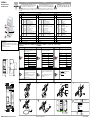
Teil Beschreibung
A
Dupline
®
-Bus
B
Informations-LED:
Grün
(EIN)
EIN
AUS
1 x blinkend
2 x blinkend
Betriebsspannung EIN
Betriebsspannung AUS
Stromversorgung ist nicht OK (<12V)
Kurzschluss zwischen POW und D+
Gelb
(Dupline-
Bus)
EIN
AUS
1 x blinkend
2 x blinkend
3 x blinkend
4 x blinkend
5 x blinkend
6 x blinkend
Kommunikation im Dupline-Bus ist OK
Keine Kommunikation im Dupline-Bus
Kurzschluss im Dupline-Bus
Fehler: Dupline Eingangsspannungs (Anschluss D-
ist nicht verbunden)
Fehler: Dupline Ausgangsspannung
Dupline Bus ist überlastet
Warnung: Dupline Bus überlastet
Dupline Anschlussleitungen (D+ und D-) sind vertauscht
Gelb
(RS485)
EIN
Kurzes Blinken
Langes Blinken
Kommunikation im RS485-Bus ist OK
Keine Kommunikation im RS485-Bus (Timeout)
Modbus frame Fehler oder falsche Modbus Adresse
C
Micro-USB Anschluss für die Programmierung über PC
D
RS485 Anschluss für Modbus RTU Kommunikation
E RS485 Bus Anschluss
F Anschluss Spannungsversorgung
Es wird kein PC benötigt
Werkseinstellungen
Wenn die Werkseinstellungen verwendet wird kann das
SD2DUG24 direkt ohne Programmierung angeschlossen
werden und ist betriebsbereit
Ein PC ist notwendig
Die Werkseinstellung des SD2DUG24 sollen geändert werden
Um die Kommunikationsparameter zu ändern verbinden Sie
bitte das SD2DUG24 mit folgenden Anschlüssen an Ihren PC:
• Mit dem Micro-USB Anschluss und einer Standard USB
Leitung* (Bild 4 und 5a)
• Über den RS485 Anschluss auf der Geräteunterseite,
mit Hilfe eines Schnittstellenwandlers* (Bild 5b)
*Nicht im Zubehör enthalten
Laden sie die Software für das SD2DUG24 unter folgender Adresse herunter
www.productselection.net
Parameter Werkseinstellungen
Modbus Adresse 1
Baudrate 9600
Datenbits 8
Parität Keine
Stoppbits 1
Anzahl der
Dupline Kanäle
128 Kanäle
Ausgänge entsprechen den Eingängen
Del Beskrivelse
A
Dupline
®
-bus
B
Informationsdiode:
Grøn
(ON)
ON
OFF
1 blink
2 blinker
Forsyning ON
Forsyning OFF
Strømforsyning er ikke OK (<12V)
Forsyning og D+ er kortsluttet
Gul
(Dupline
bus)
ON
OFF
1 blink
2 blinker
3 blinker
4 blinker
5 blinker
6 blinker
Kommunikation OK på Dupline-bus
Der er ingen kommunikation på Dupline-bus
Dupline-bus er kortsluttet
Dupline input spændings error (D-ikkeforbundet)
Dupline output spændings fejl
Dupline bus overload
Dupline bus overload fejl
Dupline (D+ og D-) ledninger er byttet
Gul
(RS485)
ON
Kort blink
Lang blink
Kommunikation OK på RS485-bus
Der er ingen kommunikation på RS485-bus (Timeout)
Modbus frame fejl eller forkert addresse
C
Micro-USB port til forbindelse til USB port for PC for programming
D
RS485 port terminal for Modbus RTU kommunikation
E RS485 bus terminering
F Strømterminaler
PC ikke nødvendig
Fabriks indstillinger
SD2DUG24 kan monteres og ibrugtages direkte uden
programmering, v.h.a default parametrene:
PC nødvendig SD2DUG24 parametre kan ændres
Forbind SD2DUG24 til PC’en for at ændre kommunika-
tions parametre, ved at bruge en af de følgende porte:
• Micro-USB port v.h.a.standard USB kabel* (Figur 4
og 5a)
• RS485 porten i bunden af modulet ved at bruge en
RS485 til USB konverter* (Figur 5b)
*ikke inkluderet
Download SD2DUG24 Software fra www.productselection.net
Parameter Default værdi
Modbus addresse 1
Baud rate 9600
Data bits 8
Paritet NONE
Stop bit 1
Antal Dupline kanaler
128 kanaler
Udgange spejler input
部件 描述
A
Dupline
®
bus
B
LED指示灯:
绿色
(ON)
ON
OFF
1 闪烁
2 闪烁
电源 ON
电源 OFF
电源不正常 (<12V)
电源与D+短路
黄色
(Dupline
bus)
ON
OFF
1 闪烁
2 闪烁
3 闪烁
4 闪烁
5 闪烁
6 闪烁
Dupline总线通讯正常
Dupline总线现在没有通讯
Dupline总线短路
Dupline输入电压错误 (D- 线路未连接)
Dupline输出电压错误
Dupline总线超载
Dupline总线超载警告
Dupline (D+ and D-)线路接反
黄色w
(RS485)
ON
短闪烁
长闪烁
RS485总线通讯正常
RS485总线没有通讯(超时)
Modbus帧或者地址错误
C
微型USB接口连接到PC的USB端口编程
D
用于Modbus-RTU通讯的RS485端口终端
E
RS485端口终端
F
电源连接区
没有电脑情况下
出厂设置
SD2DUG24可以直接供电无需任何设置,使用默认参数
有电脑情况下 可以修改SD2DUG24参数
将SD2DUG24连接到PC可以修改参数,可以使用下列端口
• 使用标准USB数据线* 的微型USB接口(图4和5b)
• 模块底部的RS485端口端子。
使用RS485到USB转换器* (5b图)
*需另行购买
下载SD2DUG24软件网址www.productselection.net
参数 默认值
Modbus 地址 1
波特率 9600
地址位 8
奇偶性 NONE
停止位 1
Dupline通道数量
128通道
输出重复输入
!"#$
%!&#'
$($
$($
-20°C to +50°C
(-4°F to 122°F)
-50°C to +85°C
(-58°F to 185°F)
5a
5b
Zulassungen/Zeichen: CE, cULus entsprechend UL60950.
Anmerkung zur UL:
• Die Versorgung des Gerät muß von einem gelisteten Information
Technology Equipment AC Adaptor mit der Kennzeichnung NEC Class 2
oder LPS erfolgen.
• Maximale Umgebungstempertur: 40°C
-
 1
1
-
 2
2


CARLO GAVAZZI SD2DUG24 Guida d'installazione
- Tipo
- Guida d'installazione
in altre lingue
Documenti correlati
-
CARLO GAVAZZI CPTDINAV51HA3AX Guida d'installazione
-
CARLO GAVAZZI SH2DSP24 Manuale del proprietario
-
-
-
-
-
-
-
-
CARLO GAVAZZI SHJWEM16A230 Manuale utente