
Sauter GmbH
Ziegelei 1
D-72336 Balingen
E-Mail: info@sauter.eu
Tel.: +49-[0]7433- 9933-199
Fax: +49-[0]7433-9933-149
Internet: www.sauter.eu
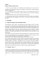
Instruction Manual
Mobile digital Leeb Impact
Hardness Tester
SAUTER HMO
Version 1.2
07/2015
GB
HMO-BA-e-1512
PROFESSIONAL MEASURING

2 HMO-BA-e-1512
GB
SAUTER HMO
Version 1.2 07/2015
Instruction Manual
Mobile digital Leeb Impact Hardness Tester
Thank you for buying a digital SAUTER Leeb impact hardness tester. We hope you
are pleased with your high quality instrument and with its big functional range. If you
have any queries, wishes or helpful suggestions, do not hesitate to call our service
number.
Summarize:
1 Overview ......................................................................................................... 4
1.1 Application range of measurement principle ........................................................................ 4
1.2 Hardness value „L“ .................................................................................................................. 4
1.3 Main features ............................................................................................................................ 5
1.4 Application range ..................................................................................................................... 5
1.5 Technical Information .............................................................................................................. 5
1.5.1 Display unit ................................................................................................................................. 5
1.5.2 Impact devices ............................................................................................................................ 6
1.6 Display unit overview ............................................................................................................... 9
2 Checking supplied accessories.................................................................... 9
3 Quick start guide.......................................................................................... 10
3.1 Necessary connection ........................................................................................................... 10
3.2 Charge battery ........................................................................................................................ 10
3.3 Calibration information .......................................................................................................... 10
4 Operation instruction .................................................................................. 10
4.1 Display ..................................................................................................................................... 10
4.1.1 Keyboard description ................................................................................................................ 10
4.1.2 Measurement mode .................................................................................................................. 11
4.1.3 Adjusting the LCD contrast manually ....................................................................................... 11
4.1.4 Selecting the Type of Impact Device ........................................................................................ 12
4.2 Using the Menu ....................................................................................................................... 12
4.2.1 „Testing“ Setup ......................................................................................................................... 13
4.2.2 Printing Setup ........................................................................................................................... 16
4.2.3 Memory Management............................................................................................................... 18
4.2.4 System Setting ......................................................................................................................... 20
4.2.5 Calibration ................................................................................................................................ 22
4.2.6 Information ................................................................................................................................ 25
4.3 Charging .................................................................................................................................. 25
4.4 Backlight ................................................................................................................................. 26
4.5 Reset ........................................................................................................................................ 26
4.6 Automatic Shutdown .............................................................................................................. 26
5 Data Printing ................................................................................................ 26
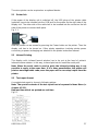
5.1 Printer link ............................................................................................................................... 27
5.2 Infrared Printing ...................................................................................................................... 27
5.3 Test report format ................................................................................................................... 27
5.4 Test report printing ................................................................................................................ 28
5.4.1 Automatic Printing .................................................................................................................... 28
5.4.2 Manual Printing ......................................................................................................................... 28
5.4.3 Assemble Printing ..................................................................................................................... 28
5.4.4 Other Printing ways .................................................................................................................. 28

HMO-BA-e-1512 3
6 Hardness Test .............................................................................................. 29
6.1 Test preparation ..................................................................................................................... 29
7 Troubles and solutions ............................................................................... 30
8 Maintenance and Service ............................................................................ 30
8.1 Impact device maintenance ................................................................................................... 30
8.2 Storage of the report .............................................................................................................. 30
8.3 Normal Maintenance procedure ............................................................................................ 31
8.4 Service ..................................................................................................................................... 31
9 Declaration of Conformity ........................................................................... 34

4 HMO-BA-e-1512
Caution
Please carefully read this first:
1. Only the special battery and provided power adapter may be used for the
hardness tester. Otherwise it may cause damages to the product i.e. battery leakage,
even fire or explosions.
2. Any components of the hardness tester may not be submerged into water or
exposed to rain which could cause a battery explosion and the instrument might be
damaged.
3. To avoid electrical shocks, the housing may not be opened.
4. If the instrument isn’t used for a longer period, it has to be stored in cool and dry
surroundings after fully charging it once a year. This serves to maintain the battery
functions.
1 Overview
1.1 Application range of measurement principle
Physically seen, HMO tester is a really simple dynamic hardness tester. An impact
sensor with a hard metal tip is pressed with spring force against the surface of the
test object. The surface might be slightly damaged, if the impact module strikes onto
the surface, resulting a lack of kinetic energy. This lack of energy is calculated by the
velocity measurements, in the way, when the impact sensor is located in a special
distance to the surface, during the impact and releasing phase of the test. The fix
magnet in the impact body produces an induction tension in the wire bobbin of the
impact body.
The tension of the signal comports itself proportionally to the velocity of the impact
body. The signal processing of the electronics guarantees that the hardness value
can be read on the display and memorized in the instrument.
Harder materials are producing a higher impact velocity than softer ones.
This hardness tester allows a direct hardness measurement within many material
groups (e.g. steel aluminium) and this can be valued as a final test result in Leeb
hardness without conversion. Nevertheless you can convert into other hardness
scales with this tester. These conversions into other hardness scales (HRC, HRB,
HB, HV, HSD etc.) are programmed in the hardness tester and can be displayed
directly. But this might only serve as a reference, it is not really exact. All data are
memorized in the initial Leeb scale, just to be free of any measurement errors.
1.2 Hardness value „L“
This term was introduced 1978 into measuring technology by Dr. Dietmar Leeb. It
contains the quotient for the impact body’s rebound and impact velocity, multiplied by
1000. Harder materials produce higher rebound velocity than less harder ones. With
reference to a particular material group (i.e. steel, aluminium etc.), the L value

HMO-BA-e-1512 5
represents a direct hardness measurement and is used as such. Comparison curves
with other standard statistic hardness values have been established (Brinell, Vickers,
Rockwell C, B) for the most prevalent materials, enabling the
L values to be converted into the relevant values by these procedures. With this
hardness tester, such hardness values can directly be displayed in the hardness
scales HRC, HRB, HB, HV, HSD and tensile strength (MPa).
1.3 Main features
- Highly accurate, ± 6 HL
- Automatic correction for impact direction
- Large, easy to read display with backlight
- English, German, French, Italian, Spanish, Russian, Chinese simplified,
Chinese traditional
- User profiles for fast change of all settings
- Operation with Touch Screen
- Large memory with on- screen review of data
- Conversion to all common hardness scales HRC, HRB, HB, HV, HSD
and tensile strength (MPa)
- Rechargeable Li- ion batteries
- Conforms to the standards DIN 51056 and ASTM A 956-02.
1.4 Application range
- Appropriate for all metals
- Ideal for production level testing
- Best suited for on- site testing of heavy, big or already installed parts
- Handy for difficult to access or confined test locations
- Automatic compensation for impact direction
- Excellent for material selection and acceptance tests
- Easy to handle and accurate on curved test surfaces (R> 10mm)
- Metal production & processing
- Automotive & transportation
- Aerospace & shipyard
- Testing services & laboratories
1.5 Technical Information
1.5.1 Display unit
• HL Display Range: 0 ~ 1000 HL
• Accuracy: ± 6 HL
• Display of the main body: large LCD with adjustable contrast, backlight, Touch
Screen
• Unit Material: shock resistant ABS plastic

6 HMO-BA-e-1512
• Internal Data Storage : ~ 800 measured values
• Resolution: 1 HL; 1 HV; 1 HB; 0,1 HRC; 0,1HRB; 1 HSD; 1 MPa
• Battery type: rechargeable Li- Ion
• Operating temperature: 0°C up to + 50°C (32°F up to 122°F)
• Storage Temperature: -10°C up to + 60°C (14°F up to 140°F)
• Humidity: 90 % max.
• Dimension: 135 x 83 x 24mm (5.3 x 3.2 x 0.9 Inches)
• Weight: 228 g
1.5.2 Impact devices
The HMO is fitted with the universal impact device D. Special impact devices are
available for usage in extremely confined spaces with special components of
geometry or surface finish. These additional types significantly extend the
possibilities of application from HMO. Each special impact device is compatible with
unit D indicating device and is supplied as accessory.
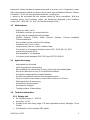
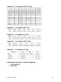
1.5.2.1 Impact device type D
Application: For the majority of your hardness testing assignments.
Impact weight: 75 g
Impact energy: 11 Nmm
Mass of the impact body: 5.5 g
Test tip diameter: 3 mm
Test tip material: tungsten carbide
Test tip hardness: ≥ 1600 HV
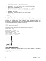
1.5.2.2 Impact device type DC
Application: Used in very confined spaces, e.g. in holes, cylinders or for internal
measurements on assembled machines.
Weight: 50 g

HMO-BA-e-1512 7
1.5.2.3 Impact device type DL
Application: For measurements in extremely confined spaces or at the base of
grooves.
Weight: 100 g
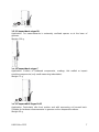
1.5.2.4 Impact device type C
Application: Surface of hardened components, coatings, thin walled or impact
sensitive components (only small measuring indentation).
Weight: 75 g
1.5.2.5 Impact device type D+15
Application: Particularly slim front section and with measuring coil moved back.
Suitable for hardness measurements in grooves and on deepened surfaces.
Weight: 80 g

8 HMO-BA-e-1512
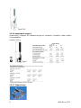
Type D+15
1.5.2.6 Impact device type G
Anwendung: Geeignet für Härtemessungen an schweren Gussteilen sowie soliden
Schmiedeteilen.
Gewicht: 250 g
Type G
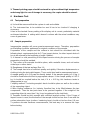
1.5.2.7 Support rings

HMO-BA-e-1512 9
On curved surfaces having a radius less than 30 mm, effective positioning on the test
object is facilitated by the use of support rings (set of 12 pcs.). The appropriate
support ring has to be screwed onto the front of the impact device. The set includes
cylindrical, hollow-cylindrical, spherical or hollow-spherical surfaces with a radius of
11 mm. Special support rings can be manufactured for geometrically complex
surfaces.
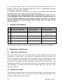
1.5.2.8 Application criteria
The support rings are valid for impact devices D, DC, DL, C, D+15, G. As standard
practice for hardness measurements, the measuring location surface should be
bright and smoothly. It does not have to be polished. Any damage to the test piece
surface will be minimal by testing with the HMO. At least, 2 or 3 test impacts should
be performed at each measuring location and then, in all cases, the average should
determine for the individual readings. A surface of 10 x 10 mm is sufficient for
measurement purposes. The device can also be used without special preparation
using the impact device D. Slim work pieces and those weighing between 2 and 5 kg
must be placed on a solid base plate for testing in the way that the force of the
impact neither shifts them nor causes them no flex, as otherwise the readings could
be falsified. Compact miniature parts with plane measuring surfaces can also be
tested, but they have to be “coupled” for the purpose with a rigid base. “Coupling” is
arranged by lightly coating the test object with coupling gel and sticking it firmly to a
base plate of adequate weight.
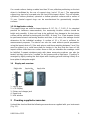
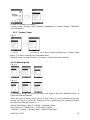
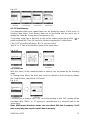
1.6 Display unit overview
Right side front side back side
1. Sensor jack
2. LCD Display
3. Printer and charger jack
4. Reset hole
5. IrDA window
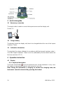
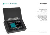
2 Checking supplied accessories
It should be checked that the following accessories are supplied with your instrument
(Fig. 2.1):

10 HMO-BA-e-1512
3 Quick start guide
3.1 Necessary connection
The signal cable is used to connect the impact sensor and the display unit.
Picture 3-1
3.2 Charge battery
The battery (inside the display unit) has to be charged before first use of the Impact
Hardness Tester.
3.3 Calibration information
The test block has been calibrated in accordance with the dynamic hardness value L.
The HMO Impact Hardness Tester has to be calibrated by the test block before the
first use (see item 4.2.5.1).
4 Operation instruction
4.1 Display
4.1.1 Keyboard description
The Power on/off button has to be pressed to turn on the instrument. In any case,
this button can be pressed again for one second to turn it off.
Note: During the instrument is charging, to monitor the charging state, the
instrument cannot be turned off by pressing this button!

HMO-BA-e-1512 11
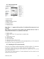
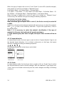
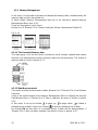
4.1.2 Measurement mode
1. Impact unit type
2. Material group
3. Battery remaining indicator
4. Hardness value L
5. Impact direction
6. Conversion value
Note: When “---“ appears at this position, it is indicated that conversion is out
of range.
When there is no message at this position, this indicates that the “Scale” is
being set and that there is no conversion in this time.
7. Statistic values
8. Statistic times value: The impact times in a statistic data
group
9. Impact times counter
10. Time and date
11. Print current value
12. Adjustment of the contrast of LCD
13. Backlight on/off: it has to be clicked and the backlight will turn on if it is turned off;
if it is turned on, it has to be clicked to turn it off.
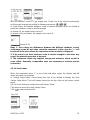
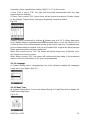
4.1.3 Adjusting the LCD contrast manually
Due to the use of different ambient temperatures and light conditions, it is necessary
to adjust the contrast of the LCD for a better observing and reading of data.
If “A” area is clicked, the dialog box which adjusts the contrast of the LCD, can be
opened (see picture 4-2).
Then it has to be clicked directly to “Contrast Adjustment” and the contrast can be
adjusted on the touch screen.

12 HMO-BA-e-1512
After this is achieved, “A” area has to be clicked to confirm the contrast and to close
this dialog box.
If there is no operation within 3 seconds during the dialog box is opened, it will close
automatically. After adjusting the contrast, it will be stored to its original state as long
as “A” area isn’t clicked again for the next current operation.
Fig. 4-2
4.1.4 Selecting the Type of Impact Device
It has to be clicked on the icon “D” in the upper left corner of Fig. 4-1 to change the
type of impact unit. D Type impact unit, G Type impact unit. If other types are
needed, please contact us.
Note: 1. Make sure that the correct type of impact device has been chosen,
otherwise the test value will be incorrect.
2. This operation is only valid in the main interface.
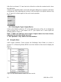
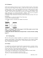
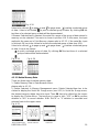
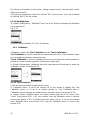
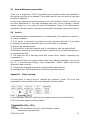
4.2 Using the Menu
HMO Impact Hardness Tester selects the Multistage Menu Mode, as shown in
picture 4-3. In Measuring Mode, MENU has to be clicked on the screen to display the
menu:
Fig. 4-3
Fig. 4-4 From Measurement mode into Menu mode

HMO-BA-e-1512 13
Picture 4-4 contains six options:
Testing Setup, Printing Setup, Memory Management, System Setting, Calibration
and Information.
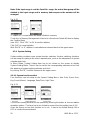
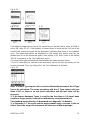
4.2.1 „Testing“ Setup
Fig.4-5
Testing Setup item has to be clicked in Menu Mode to display the Testing Setup
Menu. This Menu contains five selectable items:
Material Group, Impact Direction, Conversion, Limit Values and Statistics.
4.2.1.1 Material group
Fig. 4-6
Fig. 4-7
In Measuring Mode, the touch pen has to be used to click the “Material Group” to
select the desired material.
When the type of impact unit is set to D and “Scale” is set to hardness scale (see
picture 4-6) and it is clicked on “Material Group” continuously, the material changes
according to following sequence:
Steel & Cast Steel→ Alloy Tool Steel→ Stainless Steel→
Grey Cast Iron→ Ductile Iron→ Cast Alloys→ Brass
→Bronze→ Copper→ Forging Steel→ Steel & Cast Steel..

14 HMO-BA-e-1512
When the type of impact unit is set to D and “Scale” is set to MPa (tensile strength),
(see picture 4-7) and if it is clicked on “Material Group”
Low Carbon Steel→ Hi Carbon Steel→ Chrome Steel→
Cr-V Steel→ Cr-Ni Steel→ Cr- Mo Steel→Cr-Ni-Mo Steel→ Cr-Mn-Mo Steel→ Cr-
Mn-Si Steel→ Hi Strength Steel→ Stainless Steel→ Low Carbon Steel…
When the type of impact unit is set to G and if it is clicked on “Material Group”
continuously, the material changes according to following sequence:
Note: When the type of impact unit is set to G, the Scale can only be set to HV
or HRB.
It has to be clicked onto the desired material with the touch pen to select the material.
With or it has to be scrolled up and down. To get to the upper menu, it has to
be clicked “Back”.
Note: 1. It is necessary to select the material classification. If the type of
material isn’t known, the handbook will provide assistance.
2. If the material group has been changed, the impact times counter will be set
to “0”.
4.2.1.2 Impact direction
In measurement mode, the touch pen is used to click to “Impact direction” logo to set
the desired impact direction. If it is clicked continuously on that logo, the impact
direction changes according to following sequence:
The desired position has to be chosen and clicked.
Picture 4-8
4.2.1.3 Scale
In measurement mode, the touch pen has to used to click on “Scale” logo to select
the desired hardness scale or tensile strength. With the selected D Type impact unit,
“Scale” has to be clicked continuously and the scale changes according to following
sequence:
Picture 4-9

HMO-BA-e-1512 15
With the selection of the G Type impact unit, “Scale” has to be clicked continuously
and the scale changes according to following sequence:
In Scale Menu, the desired hardness scale or tensile strength has to be clicked to
select the hardness scale or tensile strength.
In picture 4.9, the impact unit is set to D.
In picture 4.10 (see below), the impact unit is set to G.
Picture 4-10
Note: 1. Since there are differences between the different hardness scale’s
valid range, some HL test value cannot be converted. In this case, the “---“ will
be shown at the place where the conversion value normally is displayed.
2. If the scale is set from hardness scale to tensile strength or the other way
round, the material group has to be reset.
3. The conversion value only supplies the general reference, which results in
some offset. Generally, comparative tests are necessary to achieve precise
conversion.
4.2.1.4 Limit values
When the measured value “L” is out of the limit value range, the display unit will
alarm and send out a prompt.
In Testing Setup Menu, Limit Values item has to be clicked to display the Limit
Values Setup Menu. The Limit Values have to be set by a click on the screen control
panel.
OK has to be clicked to confirm the Limit Values Setup.
Click back to cancel the Limit Values Setup.
Click to select a desired bit.
Fig. 4-11

16 HMO-BA-e-1512
4.2.1.5 Statistics
HMO Impact Hardness Tester has got an automatic statistic function. If the impact
times are up to the Statistic Times Value, value ( the mean value of the measured
hardness value L) and „S“ value (the difference of the max. value and the min. value)
are automatically formed and displayed on the screen. In Measurement Mode,
“Statistic “ item has to be clicked with the touch pen to display the Statistic Times
Value setup menu; or in Testing Setup Menu, “Statistic “ item has to be clicked to
display the Statistic Times Value setup menu (see picture 4-12).
The Statistic Times Value has to be set by a click on the screen and then OK has to
be clicked.
Click OK again to confirm the Statistic Times Value entry.
Click BACK to cancel the procedure.
Click to increase or decrease the Statistic Times Value.
Fig. 4-12
Note: 1. The Statistic Times Value range is 1~99. If this value is set to 1, the
system has got no Statistic process.
2. When this value has been reset, the impact times’ counter will start counting
from “0”.
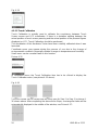
4.2.2 Printing Setup
With the Micro-printer (optional available) it is possible to print out the measured
values in many formats. In Menu Mode, Printing Setup has to be clicked to display
the Printing Setup Menu (see picture 4-13). There are three options in this menu:
Items, Print Memory and Print All.
4.2.2.1 Items
A complete test result report should include: measured values, conversion values,
date, time, impact direction, statistic value, material etc. The printing items can be
chosen in this menu. There are five options in this menu:
Date, Time, Direction, Mean Value and Material (see 4-13)
In Items Menu, the desired item has to be clicked to display its Function Switch.
“ON” or “OFF” has to be clicked to confirm the choice.
“BACK” or “X” has to be clicked to return to the upper menu.

HMO-BA-e-1512 17
Fig.4-13
4.2.2.2 Print Memory
The measured values and related items can be printed by means of this menu. In
Printing Setup Menu, Print Memory item has to be clicked with the touch pen to
display the Serial No. Range menu (see picture 4-14).
The printing range has to be set by a click on the screen control panel (click to
select a desired bit). Then OK has to be clicked to display the Confirm Menu.
Click “YES” to confirm printing or “NO” to cancel printing.
“BACK” or “X” has to be clicked to return to the upper menu.
Fig. 4-14
4.2.2.3Print all
With this menu, all the measured data in memory can be printed by the following
steps:
In Printing Setup Menu, the touch pen has to be clicked on Print All item to display
the Confirm Menu, see picture 4-15 below.
Fig. 4-15
The touch pen is used to click “YES” to confirm printing or with “NO” printing will be
cancelled. With “BACK” or “X” printing is cancelled and it is returned back to the
upper menu.
Note: HMP Impact Hardness tester can save about 800 data in memory. It will
take a very long time to print out all data in memory.

18 HMO-BA-e-1512
4.2.3 Memory Management
In this menu, it is possible to browse and delete the memory data, simultaneously the
memory data can also be printed out.
In Menu Mode, Memory Management item has to be clicked to display Memory
Management Menu (see 4-16).
There are five options in this menu:
Browse A to Z, Browse Z to A, Browse Selected, Delete Selected and Delete All.
Fig. 4-16
4.2.3.1 The Format of Memory data
The data group, such as test result, conversion result, sample material and impact
direction, are automatically saved in memory after each measurement. The format of
memory data is shown in picture 4-17:
4.2.3.2 Data Browser mode
This tester includes three browser modes: Browse A to Z, Browse Z to A and Browse
Selected.
It has to be clicked directly onto Memory Management Menu to display the relevant
Data Browse Menu. If “Browse A to Z” item is selected, the menu is shown in picture
4-16.
In this menu it has to be clicked to page up, to page down, to delete a
selected group of data. It has to be clicked to print a selected group of data.
By clicking OK the test time of a selected group of data will be demonstrated. If
“Browse Z to A” item has been selected, the menu is shown in picture 4-18.

HMO-BA-e-1512 19
Fig. 4-18
It has to be clicked to page up and to page down, to delete a selected group
of data. It has to be clicked to print a selected group of data. By clicking OK the
test time of a selected group of data will be demonstrated.
If Browse Selected item is desired, the serial No. range of the group of data stored in
memory can be selected. This menu is shown in picture 4-19. In this menu, the input
method is the same as in Print Memory, please refer to 4.2.2.2. If the serial No. input
is finished, OK has to be clicked to browse the selected group of data (see 4-20).
It has to be clicked to page up and to page down, to delete a selected group
of data. It has to be clicked
to print a selected group of data. By clicking OK the test time of a selected
group of data will be demonstrated.
Fig. 4-19 Fig. 4-20
4.2.3.3 Delete Memory Data
There are three ways to delete memory data:
1. Delete Memory Data in Data Browser Menu,
please refer to 4.2.3.2.
2. Delete Selected: In Memory Management menu, Delete Selected item has to be
clicked to display the Serial No. Range menu (see 4-21).In Serial No. Range menu,
the desired range to delete has to be input. Then OK has to be clicked on the screen
to display the Confirm Menu. The touch pen is used to click “YES” or OK to confirm
deletion or “NO” to cancel deletion. With “BACK” or “X” deletion is cancelled and
returned back to the upper menu.
Fig. 4-21

20 HMO-BA-e-1512
Note: If the input range is out the Serial No. range, the actual data group will be
deleted in the input range and in memory data sequence the number will be
arranged.
Fig. 4-22
3. Delete All: This operation will delete all data in memory.
To do this, in Memory Management it has to be clicked onto Delete All item to display
the Confirm Menu
(see 4-21). Click “YES” or OK to confirm deletion.
Click “NO” to cancel deletion.
With “BACK” or “X” deletion is cancelled and returned back to the upper menu.
4.2.4 System Setting
System setting contains some system function switches. Various switching functions
can be setup according to the users’ requirements, such as the adjustment of system
calendar and clock.
In Menu Mode, System Setting item has to be clicked on the screen to display
System Setting Menu. There it can be set for the corresponding switches to turn into
the windows of system setting calendar and clock.
By clicking “BACK”, it will be returned to the upper menu.
4.2.4.1 System function switch
Four functions can be setup on the System Setting Menu: Auto Print, Gross Error,
Key Sound (Alarm), Language, Date/Time, Light Time.
Fig. 4-23
The function-setting window can be opened by pressing the button to choose relative
operation options. This item has to be clicked to conduct function-setting (see 4-23).
It can be chosen to turn this function on or not. It has to be clicked directly ON or
OFF to confirm the amendment.
La pagina si sta caricando...
La pagina si sta caricando...
La pagina si sta caricando...
La pagina si sta caricando...
La pagina si sta caricando...
La pagina si sta caricando...
La pagina si sta caricando...
La pagina si sta caricando...
La pagina si sta caricando...
La pagina si sta caricando...
La pagina si sta caricando...
La pagina si sta caricando...
La pagina si sta caricando...
La pagina si sta caricando...
-
 1
1
-
 2
2
-
 3
3
-
 4
4
-
 5
5
-
 6
6
-
 7
7
-
 8
8
-
 9
9
-
 10
10
-
 11
11
-
 12
12
-
 13
13
-
 14
14
-
 15
15
-
 16
16
-
 17
17
-
 18
18
-
 19
19
-
 20
20
-
 21
21
-
 22
22
-
 23
23
-
 24
24
-
 25
25
-
 26
26
-
 27
27
-
 28
28
-
 29
29
-
 30
30
-
 31
31
-
 32
32
-
 33
33
-
 34
34


in altre lingue
- English: sauter SAUTER HMO User manual
Documenti correlati
Altri documenti
-
 Screening Eagle Equotip 550 Guida Rapida
-
Yamaha V4.0 Manuale del proprietario
-
Yamaha V3 Manuale del proprietario
-
-
-
-
-
Lindy Test-i Pro 43069 Manuale utente
-
-
Starrett SR160 Manuale utente
