Yamaha PM1D Manuale utente
- Categoria
- Attrezzatura musicale
- Tipo
- Manuale utente
Questo manuale è adatto anche per

EE
PM1D System Software V1.6
Supplementary Manual

PM1D System Software V1.6 Supplementary Manual
2
Copyright
Copying or distributing this manual in part or in whole using any method without the written permission of
Yamaha Corporation is prohibited.
Tr ade marks
Company names and product names are trademarks and registered trademarks of their respective owners.
Symbols such as ® and TM are not explicitly given in this document.
The illustrations and LCD screens as shown in this owner’s manual are for instructional purposes only, and may
appear somewhat different from those on your instrument.

Contents
3
Contents
Additions and changes in V1.6 . . . . . . . . . . . . 4
Improvements to functions that were added
in V1.5 . . . . . . . . . . . . . . . . . . . . . . . . . . . . . . 5
Panel Assign in the ST IN block . . . . . . . . . . . 5
Panel display of the unit name . . . . . . . . . . . 7
Channel name area added to the EQ CH and
LCR screens. . . . . . . . . . . . . . . . . . . . . . . . . . . 8
Channel name area. . . . . . . . . . . . . . . . . . . . 8
DCA Auto Naming function. . . . . . . . . . . . . . . 9
DCA auto naming procedure . . . . . . . . . . . . 9
Input Channel Auto Naming function. . . . . . 11
Input Channel Auto Naming procedure . . . 11
Pan Nominal Position. . . . . . . . . . . . . . . . . . . 13
Pan Nominal Position procedure . . . . . . . . . 13
DCA Unity. . . . . . . . . . . . . . . . . . . . . . . . . . . . 14
DCA Unity procedure . . . . . . . . . . . . . . . . . 14
Scene Link Event . . . . . . . . . . . . . . . . . . . . . . 15
Scene Link Event procedure . . . . . . . . . . . . 15
Selective Recall . . . . . . . . . . . . . . . . . . . . . . . . 18
Extended functionality for Recall Safe. . . . . . 21
Recall Safe is now possible for compressor
and gate . . . . . . . . . . . . . . . . . . . . . . . . . . 21
Clear Library. . . . . . . . . . . . . . . . . . . . . . . . . . 22
Extended functionality for the attenuators. . 23
Global Channel Copy . . . . . . . . . . . . . . . . . . . 24
CH COPY screen . . . . . . . . . . . . . . . . . . . . . 24
Using the Global Channel Copy function . . 25
Input Meter Bridge . . . . . . . . . . . . . . . . . . . . 27
FIXED CH mode . . . . . . . . . . . . . . . . . . . . . 28
FOLLOW PANEL mode . . . . . . . . . . . . . . . . 31
Parameter Lock/Console Lock . . . . . . . . . . . . 33
SECURITY screen . . . . . . . . . . . . . . . . . . . . . 33
Setting the System Password/Console
Password. . . . . . . . . . . . . . . . . . . . . . . . . . 34
Parameter Lock . . . . . . . . . . . . . . . . . . . . . . 35
Console Lock . . . . . . . . . . . . . . . . . . . . . . . 36
Surround panning . . . . . . . . . . . . . . . . . . . . . 37
SURR PRM screen . . . . . . . . . . . . . . . . . . . . 37
Internal settings and operation in surround
mode . . . . . . . . . . . . . . . . . . . . . . . . . . . . 40
Making surround pan settings. . . . . . . . . . . 43
Cautions regarding surround pan . . . . . . . . 45
Multi-band dynamics processor. . . . . . . . . . . 46
File transfer mode . . . . . . . . . . . . . . . . . . . . . .47
Additional preference items . . . . . . . . . . . . . .48
Preset Effects Programs (added in V1.6) . . . .49
Effects Parameters (added in V1.6). . . . . . . . 49
Scene Memory/Effect Library to Program
Change Table. . . . . . . . . . . . . . . . . . . . . . . . .50
MIDI control change NRPN (Non Registered
Parameter Number) assignment table . . . . 50
MIDI Data Format . . . . . . . . . . . . . . . . . . . . . .53

PM1D System Software V1.6 Supplementary Manual
4
This supplementary manual explains the functionality that has been added or changed in PM1D system soft-
ware V1.6. Please use this manual in conjunction with the existing manuals.
*In cases where the console (CS1D) display differs from the screen of the PM1D Manager application program, expla-
nations that apply only to the PM1D Manager are distinguished by an indication of [PM1D Manager].
Additions and changes in V1.6
The additions and changes made in PM1D system software V1.6 are summarized below. For details on each
function, refer to the corresponding page.
■
Improvements to functions that were
added in V1.5 (
→
p.5)
Of the new functions that were added in V1.5, “Panel
Assign” and “Unit Name” have been improved.
■
Channel name area added to the EQ
CH and LCR screens (
→
p.8)
An area that displays the channel names has been
added to the EQ CH screens of the IN EQ function,
and to the LCR screen of the PAN/ROUTING.
■
DCA Auto Naming function (
→
p.9)
The DCA [NAME] indicator in the DCA GROUP
block can now be made to display the channel names
of the two last-assigned channels.
■
Input Channel Auto Naming function
(
→
p.11)
You can now make the INPUT block INPUT
[NAME] indicator always display the port name.
■
Pan Nominal Position (
→
p.13)
You now have the option of specifying that paired
input channels (or ST IN channels) will be at nomi-
nal level (0 dB) when panned to far left or right.
■
DCA Unity (
→
p.14)
When cue-monitoring a DCA group, it is now possi-
ble to always monitor the unity-level signal regard-
less of the state of the DCA fader or DCA [MUTE]
switch.
■
Scene Link Event (
→
p.15)
You can now cause a pre-programmed string of
MIDI events to be output from the desired MIDI
OUT connector when a specific scene is recalled.
■
Selective Recall (
→
p.18)
A Selective Recall function has been added, allowing
you to specify for each scene, parameters/channels
that will be excluded from recall when that scene is
recalled.
■
Extended functionality for Recall Safe
(
→
p.21)
The Recall Safe function has been extended, resulting
in slight changes to the Recall Safe screen, and add-
ing parameters that can be set to Recall Safe.
■
Clear Library (
→
p.22)
A CLEAR button has been added to each library
screen, allowing you to erase a library as desired.
■
Extended functionality for the attenua-
tors (
→
p.23)
The functionality of the input channel attenuators
has been expanded to allow cut/boost in a range of
–96 to +24 dB.
■
Global Channel Copy (
→
p.24)
Now you can choose desired parameters from the
currently selected channel, and copy them to multi-
ple channels of the same type in a single operation.
■
Input Meter Bridge (
→
p.27)
The levels of input channels and ST IN channels can
now be displayed in the meter bridge.
■
Parameter Lock/Console Lock (
→
p.33)
By specifying a password, the user can prevent cer-
tain parameters from being edited until the correct
password is input, or prohibit console operations.
■
Surround panning (
→
p.37)
Surround Pan functionality has been added, allowing
sounds from an input channel to be placed in a two-
dimensional space when a multi-channel playback
system is used.
■
Multi-band dynamics processor (
→
p.46)
A multi-band dynamics processor that includes an
independent compressor for each of three bands has
been added as an effect type for the internal effects.
■
File transfer mode (
→
p.47)
Data saved on a computer in which PM1D Manager
is installed can now be uploaded to the console, and
CS1D settings can be downloaded to the computer.
■
Additional preference items (
→
p.48)
The following items have been added to the UTIL-
ITY function PREFERENCE screen.
•
PROHIBIT DCA ASSIGN ON SELECTED CH
BLOCK
•
SKIP CONFIRMATIONS FOR MIX MINUS
SHORTCUT
•
LIBRARY PROTECTION

Improvements to functions that were added in V1.5
5
Improvements to functions that were added in V1.5
The following improvements have been made to the new functions that were added in V1.5.
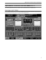
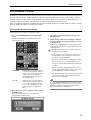
Panel Assign in the ST IN block
In V1.5, a PANEL ASSIGN screen was added to the UTILITY function, allowing the combination of input channels and
ST IN channels reflected in the panel to be specified for each individual block.

PM1D System Software V1.6 Supplementary Manual
6
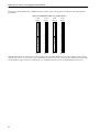
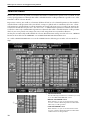
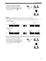
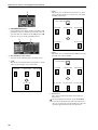
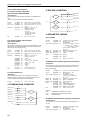
However for ST IN channels, the combinations that could be assigned to the panel were limited to the following four
possibilities.
•
The four combinations that were possible in V1.5
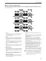
This limitation has been removed in V1.6. For example, any two ST IN channels of consecutive number such as ST IN
channels 1/2 and 5/6, or 1/2 and 7/8, can be combined freely. Also, if necessary, you may assign combinations of the same
ST IN channel to upper and lower ST IN blocks; e.g., ST IN channels 1/2 and 1/2, or ST IN channels 5/6 and 5/6.
12
34
34
12
56
78
78
56
ST IN
block 2
ST IN
block 1
ST IN
block 2
ST IN
block 1
ST IN
block 2
ST IN
block 2
ST IN
block 1
ST IN
block 1

Improvements to functions that were added in V1.5
7
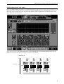
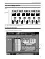
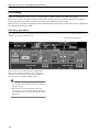
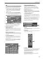
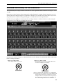
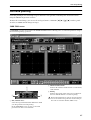
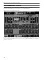
Panel display of the unit name
In V1.5, the UNIT NAME screen added to the SYS/W.CLOCK function allowed you to assign a name to each port of each
input/output unit or card. In addition, if you turned on the UNIT NAME button in the NAME MODE area at the bot-
tom of the screen, the name of the port assigned to that channel would be displayed instead of the short name of the
input channel shown in the screen.
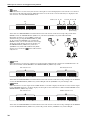
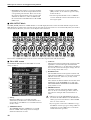
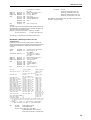
In V1.6 when you turn on the UNIT NAME button in the NAME MODE area, the INPUT [NAME] indicator in the
INPUT block will also show the name of the port assigned to that channel.
SEL
+
THR
-
COMP
+
THR
-
CLIP
6
12
18
30
60
GATE
+
THR
-
COMP
+
THR
-
GATE SEL
+
THR
-
COMP
+
THR
-
GATE SEL
+
THR
-
COMP
+
THR
-
GATE
CLIP
6
12
18
30
60
CLIP
6
12
18
30
60
CLIP
6
12
18
30
60
ONONONON
SEL
• INPUT block
Port name

PM1D System Software V1.6 Supplementary Manual
8
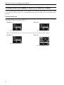
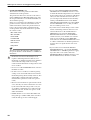
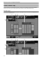
Channel name area added to the EQ CH and LCR screens
An area that displays the channel name of each channel has been added to the EQ CH screens (CH 1-24, CH
25-48, CH 49-72, CH 73-96, ST IN 1-8) of the IN EQ function and to the LCR screen of the PAN/ROUTING
function.
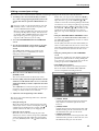
Channel name area
If the CH NAME button located in the NAME MODE area at the bottom of the display is turned on, this area will show
the short name of the corresponding channel.
•
EQ CH screen
•
LCR screen
When the UNIT NAME button is on, the name of the port assigned to that channel will be displayed.
•
EQ CH screen
•
LCR screen
Short name of the input channel
Short name of the input channel
Port name of the input channel
Short name of the input channel

DCA Auto Naming function
9
DCA Auto Naming function
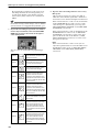
Normally, the DCA [NAME] indicator in the DCA GROUP block will display the name assigned to each DCA
group.
In V1.6, the channel names of the last-assigned two channels can also be displayed in the DCA [NAME] indi-
cator. (This is called the “DCA auto naming function.”)
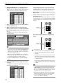
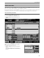
DCA auto naming procedure
The auto naming procedure is as follows.
1. Access the IN PATCH/OUT PATCH function NAME
screen.
DCA name
1
2
3
4

PM1D System Software V1.6 Supplementary Manual
10
2. In the LIST SELECT area (
1
), move the cursor to
the DCA button and press the [ENTER] switch.
The name list (
2
) will show a list of the long names
(eight characters) assigned to each DCA group.
3. In the name list, move the cursor to the column of
the desired DCA group.
4. Make sure that the cursor is located at the first
character of the text box (
3
) at right, and click the
DCA AUTO NAMING button of the character pal-
ette (
4
).
A highlighted “D” character will be input into the
character palette.
Hint
• If a PS/2 keyboard is connected to the CS1D, you
can also type Ctrl + D to input the highlighted “D”
character. (As a shortcut, you can hold down the
Ctrl key and type the first character of the button
name in the character palette.)
• When you input the highlighted “D,” no further
characters can be input into the text box. Also, any
previously-input characters will be deleted.
• To delete the highlighted “D,” click the CLEAR
button.
5. Click the ENTER button at the right of the charac-
ter palette.
A highlighted “D” character will be input in the long
name field of the name list.
The Auto Naming function is now enabled for the
corresponding DCA group. At this time, the DCA
[NAME] indicator will go dark if a channel has not
been assigned to the corresponding DCA group.
6. As necessary, perform the same operation for other
DCA groups.
7. Assign channels to the DCA groups for which you
performed steps 3–6.
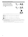
For example if you assign input channels 1 and then
2 to DCA group 1, the corresponding DCA [NAME]
indicator will show the channel names of input chan-
nels 1/2.
If you then add input channel 3 to the same DCA
group, the DCA [NAME] indicator will change as
follows.
• Be aware that when you use the DCA Auto Nam-
ing function, the DCA [NAME] indicator will
show the short names of the two last-assigned
channels.
• A maximum of twelve channels of names will be
remembered for a DCA group. If a paired chan-
nel is assigned, the lower-numbered channel will
be displayed above.
• If you remove input channel 3 from DCA group 1
in the example described above, the display will
be blank.
Hint
• If you turn on the UNIT NAME button in the
NAME MODE area at the bottom of the screen,
the DCA [NAME] indicator will show the name of
the port assigned to that channel, instead of show-
ing the short name of the input channel.
• If you turn Cue Monitor on for a DCA group for
which Auto Naming is enabled, the channel that
was last assigned to that DCA group will be
selected (its [SEL] key will light).
Channel
names
Channel
names

Input Channel Auto Naming function
11
Input Channel Auto Naming function
As explained earlier, V1.5 added the capability of displaying the channel name or port name in the INPUT
[NAME] indicator of the INPUT block.
However if necessary, it is also possible to specify that the patched port name be always displayed as the input
channel name for only a specific input channel. This is referred to as the “Input channel auto naming function.”
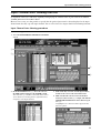
Input Channel Auto Naming procedure
The auto naming procedure is as follows.
1. Access the IN PATCH/OUT PATCH function NAME
screen.
2. In the LIST SELECT area (1), move the cursor to
the INPUT button and press the [ENTER] switch.
The name list (2) will show a list of the short names
(four characters) and long names (eight characters)
assigned to each input channel.
3. In the name list, select the desired input channel,
and move the cursor to the short name field.
4. Make sure that the cursor is located at the first
character of the text box (3) at right, and click the
UNIT NAME ASSIGN button of the character pal-
ette (4).
A highlighted “U” character will be input into the
character palette.
1
2
3
4

PM1D System Software V1.6 Supplementary Manual
12
Hint
• If a PS/2 keyboard is connected to the CS1D, you
can also type Ctrl + U to input the highlighted “U”
character. (As a shortcut, you can hold down the
Ctrl key and type the first character of the button
name in the character palette.)
• When you input the highlighted “U,” no further
characters can be input into the text box. Also, any
previously-input characters will be deleted.
• To delete the highlighted “U,” click the CLEAR
button.
5. Click the ENTER button at the right of the charac-
ter palette.
A highlighted “U” character will be input in the short
name field of the name list.
The Auto Naming function is now enabled for the
corresponding input channel. Now the port name
assigned to the channel will always be displayed in
areas of the screen that display the short name of the
corresponding channel, and in the corresponding
INPUT [NAME] indicator of the panel.
Hint
It is also possible to select the long name field instead
of the short name field in step 3. In this case, the port
name will always be displayed in areas of the screen
that display the long name of the corresponding
channel.

Pan Nominal Position
13
Pan Nominal Position
Normally if a signal sent from an input channel to the stereo bus is panned to the far-left or far-right position,
the level will increase by +3 dB compared to when the signal is panned to the center. This is done so that a
constant volume (energy) will be output whether the signal is mono or stereo; however when inputting a ste-
reo source such as a synthesizer or CD player, you may consider this an inconvenience.
Thus, V1.6 adds the option of specifying that only paired input channels (or ST IN channels) will be at nomi-
nal level (0 dB) when pan is set to far left or right.
Pan Nominal Position procedure
Use the following procedure to enable this option.
1. Access the PAN/ROUTING function CH to MIX
screen.
The PAN NOMINAL POSITION field has been
added to this screen.
• CENTER ......... If this button is on, all input chan-
nels and ST IN channels will be at
nominal level (0 dB) when panned
to the center, and +3 dB when
panned fully left or right. (This is
the default setting.)
• L ⇔ R.............. If this button is on, paired input
channels and ST IN channels will
be at –3 dB when panned to the
center, and at nominal level when
panned fully left or right (L63 or
R63).
2. Move the cursor to the L ⇔ R button and press the
[ENTER] switch.
A popup window will ask you to confirm the
changed Pan Nominal setting.
3. Move the cursor to the OK button and press the
[ENTER] switch.
4. Enable pairing for the desired channels, and make
sure that a mode other than BALANCE is selected
as the pan mode.
In this state, panning fully left or right will produce a
nominal level only for paired input channels and for
ST IN channels.
• Pan Nominal Position does not affect unpaired
monaural input channels.
• Even in the case of a paired input channel (or a
ST IN channel), this setting has no effect if the
pan mode is set to BALANCE.
• In the case of L-MONO or R-MONO, this setting
has no effect; however in the LR-MONO state,
changes in the Pan Nominal Position setting will
be valid.
• When you change the Pan Nominal Position set-
ting, the MIX SEND PAN of signals being sent to
paired MIX buses will also be switched.
• The Pan Nominal Position of each input channel
can be viewed in the graph in the PAN/ROUT-
ING function LCR screen.
Hint
By setting Pan Nominal Position to L ⇔ R, you can
minimize changes in level that occur when a paired
channel is switched between PAN, BALANCE, L-
MONO, R-MONO, or LR-MONO.

PM1D System Software V1.6 Supplementary Manual
14
DCA Unity
When cue-monitoring a DCA group, it is now possible to always monitor the unity-level signal.
In previous versions, even when you pressed the DCA [CUE] switch, you could not monitor the signal of a
DCA group whose DCA fader was lowered or whose DCA [MUTE] switch was on.
However in V1.6, you have the option of always monitoring the DCA group at unity level (the level equivalent
to setting the DCA fader at 0 dB).
DCA Unity procedure
To use this option, access the MONI/CUE function CUE/SOLO screen, and turn on the DCA UNITY ON/OFF button
that has been added to the DCA area.
If this button is on, pressing the DCA [CUE] button
allows you to monitor that DCA group at unity level,
regardless of the current position of the DCA fader or
the on/off state of the DCA [MUTE] switch.
Hint
• The setting of the DCA UNITY ON/OFF button
does not affect the individual channels included in
the DCA groups.
• If the fader of a channel included in the DCA
group is lowered or if its [ON] switch is turned off,
you will not be able to monitor that channel via the
DCA group.
DCA UNITY ON/OFF button

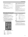
Scene Link Event
15
Scene Link Event
You can now cause a string of MIDI events to be output from the desired MIDI OUT connector when a spe-
cific scene is recalled. (This is called the “Scene Link Event” function.)
By using this function to pre-program MIDI events for each scene, you can modify the internal settings of an
external device when that scene is recalled, or automatically start the transport of an external device.
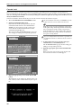
Scene Link Event procedure
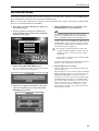
Here’s how to program MIDI events for each scene.
1. Access the SCENE function MEMORY screen.
2. In the list, click the row for the desired scene to
select it.
You cannot program MIDI events for a READ
ONLY scene or a protected scene.
3. Click the STORE button in the lower left of the
screen.
The SCENE STORE popup window will appear,
allowing you to assign a title or comment and store
the scene.
STORE button

PM1D System Software V1.6 Supplementary Manual
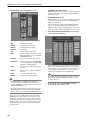
16
4. Click the COMMENT/MIDI EVENT field to select
it.
The EVENT CODE SET button will appear at the
lower left of the character palette.
5. Click the EVENT CODE SET button.
The characters in the COMMENT/MIDI EVENT
field will be erased, and a highlighted “M” character
will be input in their place. Also, the characters in the
character palette will be grayed-out except for 1, 2,
and E, and will be unavailable for input.
Hint
• If a PS/2 keyboard is connected to the CS1D, you
can also type Ctrl + E to input the highlighted “M”
character. (As a shortcut, you can hold down the
Ctrl key and type the first character of the button
name in the character palette.)
• To erase the highlighted “M,” click the CLEAR but-
ton.
6. Click either 1, 2, or E in the character palette to
select the MIDI OUT connector from which the
MIDI event will be output.
The numerals or “E” character correspond to the fol-
lowing MIDI OUT connectors.
• 1....................... MIDI OUT connector of console 1
• 2....................... MIDI OUT connector of console 2
(if using Dual Console mode)
• E ...................... MIDI OUT connector of the
engine
The highlighted numeral or “E” character will be
added to the COMMENT/MIDI EVENT field. Also,
characters in the characters palette other than 0–9
and A–F will be grayed-out, and will be unavailable
for input.
7. Use the 0–9 and A–F characters of the character
palette to directly input the MIDI event in hexadec-
imal format.
Two hexadecimal characters correspond to one byte
of the MIDI message.
8. When you have finished inputting the MIDI event,
click the AUTO STORE button or the MANUAL
STORE button.
The MIDI event you input will be stored in the scene.
You can check the contents of the MIDI event by
scrolling to the right edge of the scene list in the
MEMORY screen.
When you recall this scene, the MIDI event will be
transmitted from the specified MIDI OUT connec-
tor.
• The PM1D system is in no way aware whether the
MIDI message you input is a valid one. Please use
care when inputting the message.
• You can input a maximum of 32 bytes into the
COMMENT/MIDI EVENT field, calculated as
follows. Since a total of two bytes are used by the
highlighted “M” and the character that specifies
the output destination, you can input a maxi-
mum of 30 bytes of MIDI data here.
[Calculation method]
• One comment character .....................1 byte
• Highlighted “M”..................................1 byte
• Highlighted “1”....................................1 byte
• Highlighted “2”....................................1 byte
• Highlighted “E” ...................................1 byte
• Two characters of the MIDI message .1 byte
COMMENT/MIDI EVENT field

Scene Link Event
17
• It is possible to input two or more messages, as
long as the total stays within 32 bytes. However
you should be aware that, depending on the type
of message, the receiving device may not be able
to process MIDI events received in immediate
succession.
• If you input more than 32 bytes, a warning of
“LENGTH OVER!” will be displayed, and you
will not be able to press the STORE button.
Delete characters until the warning is no longer
displayed.
• You cannot input “FE” (Active Sensing) as a
MIDI code.
• While inputting the MIDI event, you can click
the EVENT CODE SET button and insert the
event that specifies the output destination. This
lets you output events to different MIDI OUT
connectors.
• ƒEven if you recall a scene for which a fade time is
set, the MIDI event will be transmitted immedi-
ately after the scene is recalled.

PM1D System Software V1.6 Supplementary Manual
18
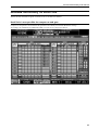
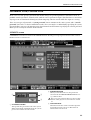
Selective Recall
In V1.6 you can restrict the parameters/channels that will be recalled when a specific scene is recalled, or con-
versely specify parameters/channels that will be excluded from the recall operation for a specific scene. (This
function is called “Selective Recall.”)
In previous versions, you could use a function called Recall Safe to select channels/parameters that would be
excluded from recall operations. These Recall Safe settings are global, and are common to all scenes. (Chan-
nels/parameters excluded from a recall operation do not change when any scene is recalled.) In contrast, the
Selective Recall function lets you store – for each scene – a combination of parameters/channels that will be
recalled, or conversely a combination of parameters/channels that will be excluded from the recall operation.
This lets you create partial scene images for store/recall, using them in a way similar to libraries.
So that you can universally enable/disable the Selective Recall function settings saved in each scene, a BYPASS
button has been added to the MEMORY screen SELECTIVE RECALL FUNCTION area.
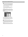
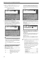
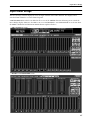
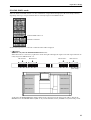
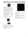
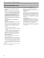
V1.6 adds a SELECTIVE RECALL screen to the SCENE function, allowing you to make Selective Recall set-
tings.
1 SELECTION MODE
Use the following two buttons to select how you want
to use the SELECTIVE RECALL screen.
• RECALL PARAMETER button
If this button is on, you can use the buttons in the
screen to select the channels/parameters that will be
affected by a recall operation.
• SAFE PARAMETER button
If this button is on, you can use the buttons in the
screen to select the channels/parameters that will be
excluded from a recall operation.
1

Selective Recall
19
Hint
Each time you switch between the RECALL PARAM-
ETER button and the SAFE PARAMETER button,
the settings in the screen will be initialized as follows.
• When you switch to the RECALL PARAMETER
button, all channels will be set to RECALL ON/
OFF button = On and RECALL PARAMETER
SELECT = ALL.
• When you switch to the SAFE PARAMETER but-
ton, all channels will be set to SAFE ON/OFF but-
ton = Off and SAFE PARAMETER SELECT = ALL.
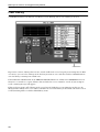
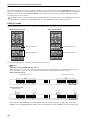
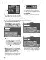
2 ENABLE/DISABLE button
This button enables (button indicates ENABLE) or
disables (button indicates DISABLE) the Selective
Recall function individually for each scene.
3 RECALL ON/OFF button
SAFE ON/OFF button
This button selects the channel that will be affected.
The function of this button will change depending
on the mode you select in the SELECTION MODE
area (1).
• If RECALL PARAMETER is on
This button will function as the SAFE ON/OFF but-
ton to specify channels that will be affected by recall
operations.
• If SAFE PARAMETER is on
This button will function as the SAFE ON/OFF but-
ton to specify channels that will be excluded from
recall operations.
The input channels/output channels for which this
function can be set are the same as in the SCENE
function RECALL SAFE screen.
4 RECALL PARAMETER SELECT button
SAFE PARAMETER SELECT button
This button selects the parameter that will be
affected. The function of this button will change
depending on the button you select in the SELEC-
TION MODE area (1).
• If RECALL PARAMETER is on
This button will function as the RECALL PARAME-
TER SELECT button to specify parameters that will
be affected by recall operations.
• If SAFE PARAMETER is on
This button will function as the SAFE ON/OFF but-
ton to specify parameters that will be excluded from
recall operations.
The types of parameters for which this function can
be set are the same as in the SCENE function
RECALL SAFE screen, with the exception that you
cannot specify UNIT (a unit patched to an input
channel) as an input channel.
5 SET ALL
If you click this button, all corresponding parameter
buttons will be turned on.
6 CLEAR ALL
If you click this button, all corresponding parameter
buttons will be turned off.
7 OTHERS
Use these buttons to select parameters other than the
above. The function of these buttons will change
depending on the button that is selected in the
SELECTION MODE area (1).
• If RECALL PARAMETER is on
These buttons select the parameters that will be
affected by recall operations.
2
3
4
5
6
7

PM1D System Software V1.6 Supplementary Manual
20
• If SAFE PARAMETER is on
These buttons select the parameters that will be
excluded from recall operations.
The parameters that can be selected are the same as
in the SCENE function RECALL SAFE screen, with
the exception that there is no MUTE MASTER (on/
off for all mute groups).
In the case of parameters for which there is only one
parameter for two adjacent odd-numbered/even-
numbered channels (such as the parameters listed
below), the parameter will be excluded from the
recall operation only if both channels are specified
for selective recall.
• HA GAIN GANG
• HA A/B LINK
• GATE LINK
• COMP LINK
• DELAY GANG
• PAN MODE
• GEQ LINK
Hint
All of the Selective Recall settings will be linked for
two paired channels, ST IN channels, or STEREO A/
B channels.
• Recall Safe and Selective Recall may be used
together. Channels/parameters that are set to
Recall Safe, or channels/parameters for which the
Selective Recall settings of the scene being
recalled exclude them from recall operations, will
not be recalled.
• If a scene is recalled in PREVIEW mode, Selective
Recall has no effect.
• If, when a scene is recalled, a conflict in pairing
settings occurs between Recall Safe and Selective
Recall, that pairing will be forcibly defeated. (The
channel that is excluded from the recall will
maintain all its parameters in the state prior to
recall.)
• However if two channels are paired in the current
scene, and only one of these channels is set to Safe
by the Selective Recall settings of the scene you
are recalling, recalling that scene will cause both
channels to be Safe, and the state prior to recall
will be maintained.
• If MIX channels set to Selective Recall have dif-
fering mix types (VARI or FIX) before and after
recall, the mix type before recall will apply.
• If you set the SELECTIVE RECALL ENABLE/
DISABLE button to ENABLE, and store a scene
in which all channels/all parameters are excluded
from recall operations, no parameters will change
when you next recall that scene. In such cases,
you can temporarily disable Selective Recall by
turning on the BYPASS button in the SELEC-
TIVE RECALL FUNCTION area of the SCENE
function MEMORY screen, so that you will be
able to recall the previous scene.
• If you later want to make changes to the combi-
nation of channels/parameters that were set to
Selective Recall, access the SCENE function
MEMORY screen, and in the SELECTIVE
RECALL FUNCTION area, turn the BYPASS
switch on before you recall that scene. Alterna-
tively, you can recall the scene in PREVIEW
mode. Then use the SELECTIVE RECALL screen
to edit the combination of channels/parameters,
and store the scene again into the same scene
number.
• If you recall a scene in which the RECALL
PARAMETER button = On and the ENABLE/
DISABLE button = ENABLE, parameters apply-
ing to the entire scene (such as fade time
ENABLE/DISABLE and TIME parameters, and
Pan Nominal Position) will not be recalled.
La pagina si sta caricando...
La pagina si sta caricando...
La pagina si sta caricando...
La pagina si sta caricando...
La pagina si sta caricando...
La pagina si sta caricando...
La pagina si sta caricando...
La pagina si sta caricando...
La pagina si sta caricando...
La pagina si sta caricando...
La pagina si sta caricando...
La pagina si sta caricando...
La pagina si sta caricando...
La pagina si sta caricando...
La pagina si sta caricando...
La pagina si sta caricando...
La pagina si sta caricando...
La pagina si sta caricando...
La pagina si sta caricando...
La pagina si sta caricando...
La pagina si sta caricando...
La pagina si sta caricando...
La pagina si sta caricando...
La pagina si sta caricando...
La pagina si sta caricando...
La pagina si sta caricando...
La pagina si sta caricando...
La pagina si sta caricando...
La pagina si sta caricando...
La pagina si sta caricando...
La pagina si sta caricando...
La pagina si sta caricando...
La pagina si sta caricando...
La pagina si sta caricando...
La pagina si sta caricando...
La pagina si sta caricando...
-
 1
1
-
 2
2
-
 3
3
-
 4
4
-
 5
5
-
 6
6
-
 7
7
-
 8
8
-
 9
9
-
 10
10
-
 11
11
-
 12
12
-
 13
13
-
 14
14
-
 15
15
-
 16
16
-
 17
17
-
 18
18
-
 19
19
-
 20
20
-
 21
21
-
 22
22
-
 23
23
-
 24
24
-
 25
25
-
 26
26
-
 27
27
-
 28
28
-
 29
29
-
 30
30
-
 31
31
-
 32
32
-
 33
33
-
 34
34
-
 35
35
-
 36
36
-
 37
37
-
 38
38
-
 39
39
-
 40
40
-
 41
41
-
 42
42
-
 43
43
-
 44
44
-
 45
45
-
 46
46
-
 47
47
-
 48
48
-
 49
49
-
 50
50
-
 51
51
-
 52
52
-
 53
53
-
 54
54
-
 55
55
-
 56
56


Yamaha PM1D Manuale utente
- Categoria
- Attrezzatura musicale
- Tipo
- Manuale utente
- Questo manuale è adatto anche per
in altre lingue
- English: Yamaha PM1D User manual
- français: Yamaha PM1D Manuel utilisateur
- español: Yamaha PM1D Manual de usuario
- Deutsch: Yamaha PM1D Benutzerhandbuch
- русский: Yamaha PM1D Руководство пользователя
- Nederlands: Yamaha PM1D Handleiding
- português: Yamaha PM1D Manual do usuário
- dansk: Yamaha PM1D Brugermanual
- čeština: Yamaha PM1D Uživatelský manuál
- polski: Yamaha PM1D Instrukcja obsługi
- svenska: Yamaha PM1D Användarmanual
- 日本語: Yamaha PM1D ユーザーマニュアル
- Türkçe: Yamaha PM1D Kullanım kılavuzu
- română: Yamaha PM1D Manual de utilizare
Documenti correlati
-
Yamaha PM1D Manuale utente
-
-
-
-
-
-
Yamaha CS1D Manuale del proprietario
-
-
-