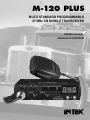
INTEK M-120 PLUS Manuale del proprietario
- Categoria
- Microfoni
- Tipo
- Manuale del proprietario

MULTI STANDARD PROGRAMMABLE
27 MHz CB MOBILE TRANSCEIVER
M-120 PLUS
OWNER'S MANUAL
MANUALE DI ISTRUZIONI

0678
NOTICE !
It is recommended to carefully read this owner’s manual before using the product. This will also help the user to
prevent using the radio in violation of the regulations valid in the country where the product is used, as well as to
avoid any possible interferences with other services.
CH
Declaration of Conformity
With the present declaration, we certify that the following products :
INTEK M-120 PLUS
comply with all the technical regulations applicable to the above mentioned products
in accordance with the EC Directives 73/23/EEC, 89/336/EEC and 99/5/EC.
Type of product : CB Transceiver
Details of applied standards : EN 300 433-1/-2, EN 300 135-1/-2
EN 301 489-1, EN 301 489-13
EN 60065
Manufacturer : INTEK S.R.L.
Via G. Marconi, 16
20090 Segrate, Italy
Tel. 39-02-26950451 / Fax. 39-02-26952185
E-mail : [email protected]
Notified Body : EMCCert Dr. Rasek
Boelwiese 5, 91320 Ebermannstadt
Germany
Identification Number : 0678
Contact Reference : Armando Zanni
Tel. 39-02-26950451 / Fax. 39-02-26952185
E-mail : [email protected]
Segrate, 23/05/2008 dr. Vittorio Zanetti
(General Manager)
DECLARATION OF CONFORMITY
EC Certificate of Conformity
(to EC Directive 99/5-89/336-93/68-73/23)
RoHS
2002/95/EC

car mounting bracket accessories (hardware, knobs, etc.)
microphone bracket
mobile antenna with magnet base (Full Kit version)
owner’s manual
Index - Introduction - Content of the packaging
- 1 -
Index - Introduction - Content of the packaging . . . . . . . . . . . . . . . . . . . . . . . . . . . . . . . . . . . . . . . . . .1
Controls and operation . . . . . . . . . . . . . . . . . . . . . . . . . . . . . . . . . . . . . . . . . . . . . . . . . . . . . . . . . . . 2 - 4
Installation . . . . . . . . . . . . . . . . . . . . . . . . . . . . . . . . . . . . . . . . . . . . . . . . . . . . . . . . . . . . . . . . . . . . . . . . 5
Installing and connecting the mobile antenna with magnet base (Full Kit Version) . . . . . . . . . . . . . 6
Frequency bands table - User Information . . . . . . . . . . . . . . . . . . . . . . . . . . . . . . . . . . . . . . . . . . . . . . 7
Frequency band selection / programming . . . . . . . . . . . . . . . . . . . . . . . . . . . . . . . . . . . . . . . . . . . . . . 8
Table of restrictions on the use of CB transceivers . . . . . . . . . . . . . . . . . . . . . . . . . . . . . . . . . . . . . . . 8
Specifications . . . . . . . . . . . . . . . . . . . . . . . . . . . . . . . . . . . . . . . . . . . . . . . . . . . . . . . . . . . . . . . . . . . . . . 9
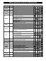
Table of restrictions on the use of CB transceivers . . . . . . . . . . . . . . . . . . . . . . . . . . . . . . . . . . . . . . . I
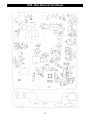
PCB - Main Board & Front Board . . . . . . . . . . . . . . . . . . . . . . . . . . . . . . . . . . . . . . . . . . . . . . . . . . . II-III
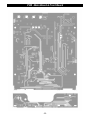
Diagram . . . . . . . . . . . . . . . . . . . . . . . . . . . . . . . . . . . . . . . . . . . . . . . . . . . . . . . . . . . . . . . . . . . . . . . . IV-V
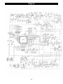
Block Diagram . . . . . . . . . . . . . . . . . . . . . . . . . . . . . . . . . . . . . . . . . . . . . . . . . . . . . . . . . . . . . . . . . .VI-VII
NOTICE !
Before using this transceiver, please check that the radio has been programmed on the frequency bands,
specifications and operating modes allowed by the regulations valid in the country where the product is used. If
not, please proceed to modify the frequency band programming, as it is described in this owner’s manual. This
transceiver is factory pre-programmed on the CE European frequency band (CEPT 40CH FM 4W).
Congratulations!
Congratulations for selecting and purchasing an INTEK quality product. This transceiver includes a number of advanced
functions and systems, therefore it is definitely necessary to carefully read this owner’s manual before using the radio.
With a correct use of the product in accordance with the operating method described in this manual, the product will offer
a trouble free use for many years. INTEK is constantly engaged to develop and provide quality products meeting the
customers requirements, however any suggestion or comments on this product that might help us to improve quality are
warmly welcome. INTEK M-120 PLUS is a CB transceiver using advanced hardware and software design, it includes
a special multi-standard programmable circuit, which allows to program the specifications of the radio (frequency
bands, operating modes, transmitter power) in compliance with the regulations valid in the various European
countries. Therefore this product can be used in any country of the European Community. The radio is delivered
factory pre-programmed on the CE European frequency band (CEPT 40CH FM 4W).
Content of the packaging
Please check that all the following items are contained in the packaging :
main unit (transceiver)
DC power cord with fuse holder and fuse
power cord with lighter adaptor plug
and fuse (Full Kit version)
condenser microphone
car mounting bracket
English

- 2 -
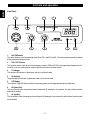
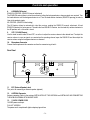
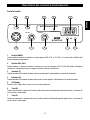
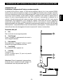
Controls and operation
Front Panel
1. AM / FM Selector
This switch allows to select the operating mode AM or FM, in both TX and RX, if the desired operating mode is enabled
by the programmed frequency band.
2. CH9 / CH19 Selector
This 3-position switch allows to select the emergency channels CH9 and CH19 in the programmed frequency band. If
the switch is set to its center position, radio will operate on the normal selected channel.
3. TX Indicator
This red color LED indicator is lighted when radio is in the transmit mode.
4. RX Indicator
This green color LED indicator is lighted when radio is in the receive mode.
5. LED Display
The large size 3-digit LED display indicates the operating channel and the programmed frequency band code.
6. DN (Down) Key
This key allows to select the operating channel downward. By keeping this key pressed, the quick channel selection
mode will be enabled.
7. UP (Up) Key
This key allows to select the operating channel upward. By keeping this key pressed, the quick channel selection mode
will be enabled.
1
9 8 7 610
2 3 4 5
TX
CH
RX
M-120 PLUS
VOLUME
MULTISTANDARD CB RADIO
OFF AS
UP DN
SQUELCH
AM FM CH9 CH19
English

- 3 -
English
Controls and operation
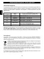
Rear Panel
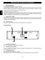
8. AS/SQUELCH Control
SQUELCH CONTROL (SQUELCH manual adjustment)
The SQUELCH control allows to silent the receiver by cutting the background noise, when no signals are received. Turn
the knob clockwise until the background noise is cut. Turn the knob counter clockwise (SQUELCH opening) in order to
listen to the weakest signals.
AS CONTROL (SQUELCH fixed setting)
The AS function allows to automatically silent the receiver, avoding the SQUELCH manual adjustment. A fixed
SQUELCH threshold is factory pre-set. To enable the fixed SQUELCH function, turn the knob fully counter clockwise to
the AS position, until a click noise is heard.
9. OFF / VOLUME Control
Use this knob to switch radio ON and OFF, as well as to adjust the receiver volume to the desired level. To adjust the
receiver volume in case no signals are received on the operating channel, open the SQUELCH and then adjust the
receiver volume using the background noise as a reference.
10. Microphone Connector
Connect the microphone to this connector and turn the connector ring to lock it.
11. EXT (External Speaker) Jack
This jack is for connecting an external speaker (optional).
12. ANTENNA Connector
Antenna connector. Refer to the sections INSTALLATION OF THE ANTENNA and INSTALLING AND CONNECTING
THE MOBILE ANTENNA WITH MAGNET BASE.
13. 13.2VDC POWER CORD
13.2VDC power cord input.
FULL KIT VERSION
The power cord is complete with lighter adaptor plug and fuse.
ANTENNA
EXT
DC
13.2V
11
13
12

Controls and operation
- 4 -
English
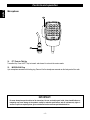
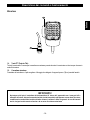
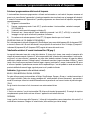
Microphone
14. PTT (Push-to-Talk) Key
Transmitter key. Press the PTT key to transmit and release it to return to the receive mode.
15. MICROPHONE Plug
4-pin microphone connector with locking ring. Connect it to the microphone connector on the front panel of the radio.
14
15
IMPORTANT !
Do never attempt to open the cabinet of the transceiver. No user serviceable parts inside. Internal modifications or
tampering may cause damage to the product, modify its technical specifications and will void warranty rights. If
service or repair are required, please go to an authorised service centre or specialized technician.

Installation
- 5 -
English
Installation
Before installing the main unit in the vehicle, check and select the most convenient location, in order that the radio will be
easy to reach and comfortable to operate, without disturbing or interfering with the vehicle drive. Use the supplied
bracket and hardware to install the radio. The bracket screws must be well tightened in order not to become loosen with
the vehicle vibrations. The car mounting bracket can be installed over or below the radio and the radio may be inclined
as desired according to the specific type of installation (under dashboard or track cabin roof installation).
Installation of the Main Unit
Before connecting the radio to the vehicle electric system, make sure that radio is switched off, with the OFF/VOLUME (9)
knob completely turned counter clockwise at OFF position. The DC power cable (13) of the radio is complete with a fuse
holder with fuse located on the red positive (+) wire. Connect the DC power cable to the vehicle electric system, with
special attention to respect correct polarity, even if the radio is protected against polarity inversion. Connect the red wire to
the positive (+) pole and the black wire to the negative (-) pole of the vehicle electric system. Make sure that the wires and
terminals are firmly and stably connected, in order to prevent cables from disconnecting or causing short circuits.
FULL KIT VERSION
Connect the lighter adaptor plug (13) to the 12VDC socket of the vehicle. Fuse is located inside the lighter adaptor plug.
To replace the fuse unscrew the cap of the plug, remove the fuse and the spring then reinstall all parts by first inserting
the spring and then the new fuse.
Installation of the Antenna
A specific mobile antenna adjusted for 27 MHz frequency range must be used. The antenna installation must be done by
a specialised technician or service centre. Please pay special attention to carefully install the antenna on the vehicle with
perfect connection to ground. Before connecting the antenna to the radio, it is necessary to check the correct operation
of the antenna with low standing wave ratio (S.W.R.), using adequate instruments. If not, the transmitter circuit of the
radio could be damaged. The antenna must be usually installed on the highest part of the vehicle, free from obstacles
and as far away as possible from any source of electric or electromagnetic noise. The RF antenna coaxial cable must
not be damaged or pressed on its way between antenna and the radio. The correct operation of the antenna and the low
standing wave ratio (S.W.R.) must be checked periodically. Connect the RF antenna coaxial cable to the antenna
connector (12), located on the rear side of the radio.
Checking Operation of the Radio
Once radio has been connected to the vehicle electric system and to the antenna, the correct operation of the system
may be checked. Please proceed as follows :
1) Check that the power cable is correctly connected.
FULL KIT VERSION
Check that power cord is correctly connected and that the lighter adaptor plug is correctly inserted in the 12VDC
socket of the vehicle.
2) Check that the RF antenna coaxial cable is correctly connected.
3) Connect the microphone to the connector (10), located on the front side of the radio.
4) Rotate the AS/SQUELCH (8) knob counter clockwise.
5) Turn radio on using the OFF/VOLUME (9) knob and adjust volume to the desired level.
6) Select the desired channel, using the channel selector keys (6, 7).
7) Rotate the AS/SQUELCH (8) knob clockwise, to cut the background noise.
8) Press the PTT (14) key to transmit and release it to receive.
The transceiver will work correctly.

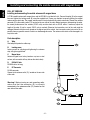
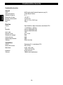
Installing and connecting the mobile antenna with magnet base
FULL KIT VERSION
Installing and connecting the mobile antenna with magnet base
A 27 MHz mobile antenna with magnet base and 4m RG-58/U is included in the kit. Connect the whip (A) to the magnet
base and tighten the locking screw (B) using the supplied tool. Please pay attention to correctly placing the magnet
antenna on the vehicle top. The magnet antenna must be firmly attached to the vehicle metal body. Connect the antenna
connector (E) to the antenna outlet (12) located on the rear side of the radio. Before turning on and operating the radio,
the correct performance of the antenna (S.W.R. ratio) must be check with an S.W.R. meter. If necessary, adjust the
length of the whip (A) until a correct S.W.R. ratio is reached. Otherwise the transmitter circuit of the radio might be
damaged. Antenna must be usually placed on the highest part of the vehicle, free from nearby metal parts and as far as
possible from any possible source of electric or electromagnetic noice. The antenna cable must not be damaged in its
way to the radio.
Parts description
A. Whip
Steel whip with protective rubber cup.
B. Locking screw
Locking screw for adjusting and tightening the antenna
whip, using the supplied tool.
C. Magnet base
Antenna magnet base to be placed on any iron or steel
surface, with no need to drill any hole on the vehicle body.
D. RG-58/U Cable
RG-58/U cable, 4m long.
E. RF Connector
PL-259 connector.
Connect to the antenna outlet (12), located on the rear side
of the radio.
Warning ! Before turning on and operating radio,
make sure that the connector (E) is correctly
connected to the antenna outlet (12) located on the
rear side of the radio.
A
B
D
E
C
- 6 -
English

Frequency bands table - User Information
- 7 -
Frequency Bands Table
The transceiver INTEK M-120 PLUS includes an advanced multi-standard programmable circuit, which allows to
program different frequency bands, specifications and operating modes, in conformity with the regulations in the country
where the product is used. 8 programmable frequency bands are available, as per the below table :
Attention ! This radio has been factory pre-programmed on the CE frequency band (CEPT 40CH FM 4W), since this
standard is currently accepted in all the European countries. Please refer to the information table at page I (Restrictions
on the use of CB transceivers).
User Information
in accordance with art. 13 of the Legislative Decree of 25th July 2005, no. 15 ”Implementation of Directives 2002/95/EC,
2002/96/EC and 2003/108/EC, relative to reduction of the use of hazardous substances in electrical and electronic
equipment, in addition to waste disposal”.
The crossed bin symbol shown on the equipment indicates that at the end of its working life the product must
be collected separately from other waste.
The user must therefore take the above equipment to the appropriate differentiated collection centres for
electronic and electro technical waste, or return it to the dealer when purchasing a new appliance of
equivalent type, in a ratio of one to one.
Appropriate differentiated waste collection for subsequent recycling, treatment and environment-friendly disposal of the
discarded equipment helps to prevent possible negative environmental and health effects and encourages recycling of
the component materials of the equipment.
Illegal disposal of the product by the user will be punished by application of the administrative fines provided for by the
legislative decree no. 22/1997 (article 50 and following of the legislative decree no. 22/1997).
FREQUENCY BAND
ID CODE
COUNTRY
SPECIFICATIONS
(Channels, Operating Modes, TX Power)
E1 ITALY/SPAIN
40CH AM / FM 4W
I2 ITALY
36CH AM / FM 4W
dE GERMANY
80CH FM 4W - 12CH AM 1W
d2 GERMANY
40CH FM 4W - 12CH AM 1W
EU EUROPE/FRANCE
40CH FM 4W - 40CH AM 1W
CE CEPT
40CH FM 4W
UUK
40CH FM 4W UK FREQUENCIES
40CH FM 4W CEPT FREQUENCIES
PL POLAND
40CH AM / FM 4W POLISH FREQUENCIES
English

Frequency band selection / programming
- 8 -
Frequency Band Selection / Programming
This two-way CB radio must be programmed and exclusively used on a frequency band allowed in the country where
the product is used. When radio is switched ON, the current programmed frequency band code will be displayed
(blinking) for about 3 seconds. To program a different frequency band, proceed as follows :
1) Turn OFF the radio.
2) Press and keep pressed the UP key (7), then turn ON the radio using the OFF/VOLUME knob (9).
3) The current frequency band code will blink on the display (5).
4) Now select the new desired frequency band code by pressing the UP (7) or DN (6) key; during the frequency
band selection process, the frequency band code will blink at a faster speed.
5) Press the PTT (14) key or wait for about 2 seconds to confirm and store the new selected frequency band
code.
UK/CE CHANNELS SELECTION (FREQUENCY BAND "U")
If the frequency band "U" (UK band) has been selected, all channels can be scrolled using the channel keys. When a
UK frequency channel will be selected the display (5) will show the channel number and the indication "U". When a
CEPT frequency channel will be selected the display (5) will show the channel number and the indication "C".
Table of Restrictions on the Use of CB Transceivers (page I)
The following information are to be considered only just as an indication. They are believed to be correct at the time of
printing this operating manual. It is however the user’s responsibility to check that, in the country where radio is used, the
regulations for the use of CB transceivers have not been modified. User is therefore suggested to contact the local
dealer or local authority, in order to check the current regulations for the use of CB transceivers, before operating this
product. The manufacturer does not take any responsibility if the product is used in violation of the regulations of the
country where the product is used.
Addendum (Updated information on national restrictions)
BELGIUM, UK, SPAIN, SWITZERLAND
In order to use this transceiver in Belgium, UK, Spain and Switzerland, residence must have an individual licence. Users
coming from abroad may freely use the radio in FM mode, while in order to use it in AM mode they must hold a licence
released in their own country.
ITALY
Foreigners arriving in Italy must get an Italian authorization.
AUSTRIA
Austria does not allow using multi standard programmable CB radios. It is recommended
to carefully follow this directives and not to use the product in the Austrian territory.
GERMANY
Along some border areas in Germany, the radio can not be used as a base station from
channel 41 to channel 80. Refer to local authority (notification office) for details.
English

Specifications
- 9 -
Specifications
General
Channels 40 FM (refer to the frequency bands table at page 7)
Frequency range 27 MHz Citizen Band
Frequency control P.L.L.
Operatine temperature -10°/+55°C
DC input voltage 13.2Vdc ±15%
Size 140 (L) x 37 (H) x 190 (D) mm
Weight 750 gr.
Receiver
System Double conversion, CPU controlled super-eterodine
IF 1° 10.695 MHz / 2° 455 KHz
Sensitivity 0.5uV for 20dB SINAD (FM)
0.5uV for 20dB SINAD (AM)
Audio output 2.5W
Audio distorsion <8% at 1 KHz
Image rejection 65dB
Adjacent channel 65dB
Signal/noise ratio 45dB
Current drain 325mA (stand-by)
Transmitter
System CPU controlled P.L.L. systhesizer
Maximum RF power 4W at 13.2Vdc
Modulation 85% to 90% (AM)
1.8 KHz ±0.2 KHz (FM)
Impedance 50 ohm unbalanced
Current drain 1300mA (at no modulation)
English

Indice - Introduzione - Contenuto della confezione
- 10 -
Indice - Introduzione - Contenuto della confezione . . . . . . . . . . . . . . . . . . . . . . . . . . . . . . . . . . . . . . .10
Descrizione dei comandi e funzionamento . . . . . . . . . . . . . . . . . . . . . . . . . . . . . . . . . . . . . . . . . . 11-13
Installazione e collegamenti elettrici . . . . . . . . . . . . . . . . . . . . . . . . . . . . . . . . . . . . . . . . . . . . . . . . . . 14
Installazione dell' antenna con base magnetica (versione Full Kit) . . . . . . . . . . . . . . . . . . . . . . . . . 15
Tabella bande di frequenza - Avviso agli utenti . . . . . . . . . . . . . . . . . . . . . . . . . . . . . . . . . . . . . . . . . 16
Selezione / programmazione della banda di frequenza . . . . . . . . . . . . . . . . . . . . . . . . . . . . . . . . . . . 17
Tabella delle restrizioni all' uso dei ricetrasmettitori CB . . . . . . . . . . . . . . . . . . . . . . . . . . . . . . . . . . 17
Caratteristiche tecniche . . . . . . . . . . . . . . . . . . . . . . . . . . . . . . . . . . . . . . . . . . . . . . . . . . . . . . . . . . . . 18
Tabella delle restrizioni all' uso dei ricetrasmettitori CB . . . . . . . . . . . . . . . . . . . . . . . . . . . . . . . . . . . I
Circuito stampato Main Board e Front Board . . . . . . . . . . . . . . . . . . . . . . . . . . . . . . . . . . . . . . . . . II-III
Schema elettrico . . . . . . . . . . . . . . . . . . . . . . . . . . . . . . . . . . . . . . . . . . . . . . . . . . . . . . . . . . . . . . . . . IV-V
Schema a blocchi . . . . . . . . . . . . . . . . . . . . . . . . . . . . . . . . . . . . . . . . . . . . . . . . . . . . . . . . . . . . . . .VI-VII
IMPORTANTE !
Prima di utilizzare la ricetrasmittente, verificare che la stessa sia programmata per operare sulle
bande di frequenza e nei modi previsti dalle norme di legge in vigore nel paese in cui la radio viene
utilizzata. Diversamente procedere alla modifica della programmazione, come indicato in questo
manuale di istruzioni. La radio è pre-programmata all' origine sulla banda di frequenza europea CE
(CEPT 40CH FM 4W).
Congratulazioni !
Congratulazioni per aver scelto ed acquistato un prodotto di qualità INTEK. Questo ricetrasmettitore dispone di numerose
funzioni avanzate e vari dispositivi, pertanto è assolutamente necessario leggere attentamente questo manuale di
istruzioni prima di utilizzare l' apparecchio. Con un uso corretto secondo quanto è indicato nel manuale di istruzioni, l'
apparecchio garantirà un servizio senza problemi per molti anni. Ci impegnamo costantemente a fornire prodotti di
qualità che rispondano alle vostre esigenze, ma siamo comunque sempre molto interessati a ricevere eventuali vostri
commenti o suggerimenti su questo prodotto, che ci aiutino nel continuo miglioramento della qualità. INTEK M-120
PLUS è un ricetrasmettitore con caratteristiche tecniche di hardware e software molto avanzate e dispone di un circuito
di tipo Multi Standard programmabile che consente di configurare i vari parametri dell' apparecchio (bande di
frequenza, modi operativi, potenza del trasmettitore) in modo conforme alle norme di legge in vigore nei vari paesi
della Comunità Europea. Pertanto questa ricetrasmittente può essere utilizzata in un qualsiasi paese della Comunità
Europea. L' apparecchio viene consegnato pre-programmato sulla banda CE (CEPT 40CH FM 4W).
Contenuto della confezione
Verificare che le seguenti parti siano contenute nella confezione :
ricetrasmettitore
cavetto di alimentazione DC con porta fusibile e fusibile
cavetto con presa accendisigari e fusibile (versione Full Kit)
microfono a condensatore
staffa di montaggio per veicolo
accessori per montaggio staffa (viti, pomelli, ecc.)
staffa di supporto per microfono
antenna con base magnetica (versione Full Kit)
manuale di istruzioni
Italiano

Descrizione dei comandi e funzionamento
- 11 -
Pannello frontale
1. Selettore AM/FM
Questo selettore consente di selezionare il modo operativo AM o FM, in TX e RX, se il modo scelto è abilitato dalla
banda di frequenza programmata.
2. Selettore CH9 / CH19
Questo selettore a 3 posizioni consente di selezionare i canali di emergenza CH9 e CH19 della banda di frequenza
selezionata. Nella posizione centrale vengono selezionati i normali canali operativi.
3. Indicatore TX
Questo indicatore LED luminoso di colore rosso è acceso quando il ricetrasmettitore è in modalità trasmissione.
4. Indicatore RX
Questo indicatore LED luminoso di colore colore verde è acceso quando il ricetrasmettitore è in modalità ricezione.
5. LED Display
Display a LED a 3-digit, indica il canale in uso o la banda selezionata.
6. Tasto DN
Questo tasto permette la selezione dei canali in ordine decrescente. Mantenendo premuto questo tasto, la selezione dei
canali avverrà in modo rapido.
7. Tasto UP
Questo tasto permette la selezione dei canali in ordine crescente. Mantenendo premuto questo tasto, la selezione dei
canali avverrà in modo rapido.
1
9 8 7 610
2 3 4 5
TX
CH
RX
M-120 PLUS
VOLUME
MULTISTANDARD CB RADIO
OFF AS
UP DN
SQUELCH
AM FM CH9 CH19
Italiano

Descrizione dei comandi e funzionamento
- 12 -
8. Manopola AS/SQUELCH
COMANDO SQUELCH (regolazione manuale SQUELCH)
Il comando SQUELCH permette di silenziare il ricevitore, eliminando il rumore (fruscio) di fondo in assenza di segnali.
Ruotare la manopola in senso orario sino a quando scompare il rumore di fondo. Ruotare la manopola in senso
antiorario (apertura dello SQUELCH) per ascoltare i segnali più deboli.
COMANDO AS (regolazione fissa SQUELCH)
E' disponibile la funzione AS per silenziare il ricevitore in modo automatico, senza eseguire la regolazione manuale dello
SQUELCH. Una regolazione fissa dello SQUELCH è pre-impostata in origine. Per impostare la funzione AS, ruotare la
manopola completamente in senso antiorario fino a farla scattare in posizione AS.
9. Manopola OFF / VOLUME
Manopola di accensione e spegnimento della radio. Permette la regolazione del volume di ascolto. In assenza di segnali
sul canale in uso, si consiglia di aprire lo SQUELCH e quindi di regolare il volume al livello desiderato utilizzando come
riferimento il rumore (fruscio) di fondo.
10. Presa per microfono
Collegare il microfono in dotazione a questa presa, bloccandolo tramite l’ apposita ghiera.
11. Presa EXT (External Speaker)
Presa per il collegamento di un altoparlante esterno (opzionale).
12. Connettore di antenna (SO-239)
Presa per il collegamento dell' antenna. Vedi capitoli "installazione e collegamenti elettrici" e "installazione dell' antenna
con base magnetica (versione Full Kit)".
13. Entrata POWER 13.2VDC
Entrata del cavetto di alimentazione DC in dotazione.
Nella versione FULL KIT, il cavetto di alimentazione è dotato di spinotto accendisigari con fusibile di protezione.
Pannello posteriore
ANTENNA
EXT
DC
13.2V
11
13
12
Italiano

Descrizione dei comandi e funzionamento
- 13 -
IMPORTANTE !
Non tentare mai di aprire il contenitore del ricetrasmettitore. All' interno dell' apparecchio non vi sono parti utili o
utilizzabili dall' utente. Interventi o manomissioni del circuito interno della radio possono causare danni alla stessa
o modificarne le caratteristiche tecniche ed inoltre violano e invalidano il diritto alla garanzia. In caso di interventi
tecnici, rivolgersi esclusivamente ad tecnico o ad un centro di assistenza autorizzato.
Microfono
14. Tasto PTT (Push-to-Talk)
Tasto di trasmissione. Premere per trasmettere e mantenere premuto durante la trasmissione e rilasciare per ritornare in
modalità ricezione.
15. Connettore microfono
Connettore del microfono a 4 poli con ghiera di fissaggio, da collegarsi alla apposita presa (10) sul pannello frontale.
14
15
Italiano

Installazione e collegamenti elettrici
- 14 -
Installazione del ricetrasmettitore
E' necessario verificare e localizzare sul veicolo la posizione più opportuna ove installare l' apparato, in modo che sia
pratico e confortevole l' utilizzo dello stesso e che l' ubicazione del ricetrasmettitore non sia in nessun modo di ostacolo
alla guida del veicolo. Per il montaggio del ricetrasmettitore, utilizzare la staffa e le viti in dotazione. Le viti di fissaggio
della staffa devono essere ben serrate in modo che le vibrazioni del veicolo non possano allentarle. La staffa può essere
montata sia sopra sia sotto l' apparecchio a seconda del tipo di installazione richiesto. Il ricetrasmettitore può anche
essere inclinato e poi bloccato nella posizione desiderata tramite i 2 pomelli di fissaggio in dotazione.
Collegamento elettrico del ricetrasmettitore
Prima di collegare l’ apparecchio al circuito elettrico del veicolo, assicurarsi che il ricetrasmettitore sia spento, ovvero che
la manopola OFF/VOLUME (9) sia girata completamente in senso antiorario in posizione OFF. Il cavetto di
alimentazione (13) del ricetrasmettitore è completo di porta-fusibile con fusibile di protezione posto sul cavo rosso del
positivo (+). Collegare il cavetto di alimentazione al circuito elettrico del veicolo, facendo molta attenzione nel rispettare
la corretta polarità, anche se l’ apparecchio è protetto contro le inversioni di polarità. Collegare il cavetto rosso al polo
positivo (+) e il cavetto nero al polo negativo (-) del circuito elettrico del veicolo. Assicurasi che il collegamento dei cavetti
sia ben eseguito e che i terminali siano ben fissati, per evitare che essi si possano staccare o causare corto circuiti.
Nella versione FULL KIT inserire lo spinotto accendisigari (13) nell' apposita presa del veicolo. Il fusibile di protezione è
posto all' interno dello spinotto stesso. Per sostituire il fusibile danneggiato, svitare il cappuccio dello spinotto, togliere il
fusibile e la molla e rimontare il tutto, inserendo prima la molla e successivamente il nuovo fusibile.
Installazione e collegamento dell’ antenna
Deve essere utilizzata un’ antenna veicolare tarata sulle frequenze CB 27 MHz. L’ installazione dell’ antenna deve
essere eseguita da un tecnico specializzato. La massima attenzione deve essere prestata nel montaggio dell’ antenna
sul veicolo e nel collegamento della stessa alla massa del veicolo. Prima del collegamento al ricetrasmettitore, è
indispensabile che sia verificato il corretto funzionamento dell’ antenna con basso livello di onde stazionarie (R.O.S.),
tramite apposita strumentazione. In caso contrario, il circuito trasmittente dell’ apparecchio potrebbe venire danneggiato.
L’ antenna deve essere normalmente montata sulla parte più alta del veicolo, libera da ostacoli e il più possibile distante
da fonti di disturbo elettrico o elettromagnetico. Il cavetto coassiale RF dell’ antenna non deve essere danneggiato o
schiacciato nel percorso dall’ antenna al ricetrasmettitore. La corretta funzionalità dell’ antenna ed il basso rapporto di
onde stazionarie (R.O.S.) devono essere controllati periodicamente. Collegare il cavo RF dell’ antenna all’ apposita
presa di antenna (12), posta sul pannello posteriore della radio.
Controllo del funzionamento del ricetrasmettitore
Una volta eseguiti i collegamenti elettrici del cavo di alimentazione e dell’ antenna, si può controllare il corretto
funzionamento del sistema. Procedere come segue :
1) Controllare che sia correttamente collegato il cavetto di alimentazione
Nella versione FULL KIT controllare che sia correttamente inserito lo spinotto accendisigari nell' apposita presa
del veicolo.
2) Controllare che sia correttamente collegato il cavetto coassiale RF dell’ antenna.
3) Collegare il microfono all’ apposita presa (10), posta sul pannello frontale della radio.
4) Ruotare il comando AS/SQUELCH (8) in senso antiorario a inizio corsa.
5) Accendere l’ apparecchio tramite la manopola OFF/VOLUME (9) e regolare il volume di ascolto al livello desiderato.
6) Selezionare il canale desiderato, tramite i tasti di selezione dei canali (6 e 7).
7) Ruotare il comando AS/SQUELCH (8) in senso orario, per eliminare il rumore di fondo.
8) Premere il tasto PTT (14) per trasmettere e quindi rilasciarlo per ricevere.
Il ricetrasmettitore dovrà funzionare correttamente.
Italiano

Installazione dell' antenna con base magnetica (versione Full Kit)
VERSIONE FULL KIT
Installazione e collegamento dell’ antenna con base magnetica
La versione Full Kit include un' antenna a 27 MHz con base magnetica, dotata di 4 mt. di cavo coassiale RG-58/U.
Inserire lo stilo (A) nella base magnetica e stringere la vite di fissaggio (B) utilizzando la chiave a brugola in dotazione.
La massima attenzione deve essere prestata nel posizionamento dell’ antenna sul veicolo. Assicurarsi che l' antenna sia
fissata con la massima aderenza al piano metallico. Collegare il connettore (E) dell’ antenna all’ apposita presa di
antenna (12), posta sul pannello posteriore della radio. Prima di utilizzare il ricetrasmettitore, è importante che sia
verificato il corretto funzionamento dell’ antenna con basso livello di onde stazionarie (R.O.S.), tramite apposita
strumentazione. Svitare leggermente la vite di fissaggio (B) e regolare l' altezza dello stilo (A) fino a raggiungere il
corretto livello di onde stazionarie e stringere nuovamente la vite (B). In caso contrario, il circuito trasmittente dell’
apparecchio potrebbe venire danneggiato. L’ antenna deve essere normalmente montata sulla parte più alta del veicolo,
libera da ostacoli e il più possibile distante da fonti di disturbo elettrico o elettromagnetico. Il cavetto coassiale RF dell’
antenna (D) non deve essere danneggiato o schiacciato nel percorso dall’ antenna al ricetrasmettitore.
Descrizione delle parti
A. Stilo
Stilo in acciaio inox nero con cappuccio protettivo.
B. Vite di fissaggio
Vite per il fissaggio e la regolazione dello stilo, tramite la
chiave a brugola in dotazione.
C. Base magnetica
Base magnetica per il fissaggio dell' antenna su superfici
metalliche, senza bisogno di effettuare alcun foro.
D. Cavo RG-58/U
Cavo coassiale RG-58/U, lunghezza 4 mt.
E. Connettore
Connettore PL-259.
Avvitare all' apposita presa (12), posta sul pannello
posteriore della radio.
Attenzione ! Prima di accendere il ricetrasmettitore,
assicurarsi che il connettore (E) dell' antenna sia
correttamente fissato alla presa della radio (12).
A
B
D
E
C
- 15 -
Italiano

- 16 -
Tabella bande di frequenza - Avviso agli utenti
Tabella bande di frequenza
Il ricetrasmettitore INTEK M-120 PLUS dispone di un avanzato circuito multi-standard programmabile, che
consente di programmare la banda di frequenza, i parametri e i modi operativi in conformità con le norme
del paese in cui viene utilizzato l’ apparecchio. Sono disponibili n. 8 bande programmabili, come dalla
seguente tabella :
Attenzione ! Il ricetrasmettitore è stato pre-programmato all’ origine sulla banda di frequenza con codice
paese CE (CEPT 40CH FM 4W), in quanto questo standard è attualmente riconosciuto in tutti i paesi
europei. Vedere la tabella delle informazioni alla pag.
I
(Restrizioni all’ uso dei ricetrasmettitori CB).
Avviso agli utenti
Ai sensi dell’art. 13 del decreto legislativo 25 luglio 2005, n. 15”Attuazione delle Direttive 2002/95/CE, 2002/96/CE e
2003/108/CE, relative alla riduzione dell’uso di sostanze pericolose nelle apparecchiature elettriche ed elettroniche,
nonché allo smaltimento dei rifiuti”.
Il simbolo del cassonetto barrato riportato sull’apparecchiatura indica che il prodotto alla fine della propria
vita utile deve essere raccolto separatamente dagli altri rifiuti.
L’utente dovrà, pertanto, conferire l’apparecchiatura giunta a fine vita agli idonei centri di raccolta
differenziata dei rifiuti elettronici ed elettrotecnici, oppure riconsegnarla al rivenditore al momento
dell’acquisto di una nuova apparecchiatura di tipo equivalente, in ragione di uno a uno.
L’adeguata raccolta differenziata per l’avvio successivo dell’apparecchiatura dismessa al riciclaggio, al trattamento e allo
smaltimento ambientalmente compatibile contribuisce ad evitare possibili effetti negativi sull’ambiente e sulla salute e
favorisce il riciclo dei materiali di cui è composta l’apparecchiatura.
Lo smaltimento abusivo del prodotto da parte dell’utente comporta l’applicazione delle sanzioni amministrative di cui al
dlgs. n. 22/1997” (articolo 50 e seguenti del dlgs. n. 22/1997).
CODICE BANDA
DI FREQUENZA
PAESE
SPECIFICHE
(Canali, modi operativi, potenza TX)
E1 ITALIA/SPAGNA
40CH AM / FM 4W
I2 ITALIA
36CH AM / FM 4W
dE GERMANIA
80CH FM 4W - 12CH AM 1W
d2 GERMANIA
40CH FM 4W - 12CH AM 1W
EU EUROPA/FRANCIA
40CH FM 4W - 40CH AM 1W
CE CEPT
40CH FM 4W
U INGHILTERRA
40CH FM 4W FREQUENZE UK
40CH FM 4W FREQUENZE CEPT
PL POLONIA
40CH AM / FM 4W FREQUENZE POLACCHE
Italiano

Selezione / programmazione della banda di frequenza
- 17 -
Selezione / programmazione della banda di frequenza
Il ricetrasmettitore deve essere programmato e utilizzato esclusivamente su una banda di frequenza ammessa nel
paese in cui viene utilizzato l’ apparecchio. La banda pre-impostata viene visualizzata con un lampeggio della durata di
3 secondi all' accensione dell' apparecchio. E’ possibile programmare una diversa banda di frequenza, eseguendo la
seguente procedura :
1) Spegnere il ricetrasmettitore.
2) Premere e mantenere premuto il tasto UP (7), quindi accendere il ricetrasmettitore, ruotando la manopola
OFF/VOLUME (9).
3) Il codice di paese impostato lampeggia sul display (5).
4) Selezionare ora il nuovo codice di paese desiderato, premendo i tasti UP (7) o DN (6); la velocità del
lampeggio sarà più rapida ad indicare la procedura di selezione.
5) Per confermare la selezione premere il tasto PTT (14) oppure attendere per circa 2 secondi.
SELEZIONE CANALI UK / CE (BANDA DI FREQUENZA U)
Se è stata programmata la banda di frequenza U (Gran Bretagna), per passare dalle frequenze UK alle frequenze CEPT
e viceversa, scorrere tutti i 40 canali della banda in uso per passare da una banda all' altra. Sul display (5) comparirà l'
indicazione U (frequenze UK) o C (frequenze CEPT) seguita dal numero del canale in uso.
Tabella delle restrizioni all’ uso dei ricetrasmettitori CB (pag. I)
Le seguenti informazioni sono date a solo titolo indicativo. Si ritiene che le stesse siano corrette al momento della
stampa del presente manuale di istruzioni. E’ tuttavia responsabilità dell’ utilizzatore del ricetrasmettitore il verificare che,
nel paese in cui viene utilizzato l’ apparecchio, non siano state introdotte variazioni alle norme di legge che abbiano
modificato le suddette restrizioni. Si consiglia quindi l’ utilizzatore di consultare il proprio rivenditore di fiducia o l’ autorità
locale al fine di verificare con esattezza le norme di legge in vigore e le restrizioni all’ uso per i ricetrasmettitori CB, prima
di utilizzare il prodotto. Il produttore non assume alcuna responsabilità per l’ uso del prodotto in modo non conforme a
quanto è stabilito dalle norme di legge, vigenti nel paese in cui il prodotto è utilizzato.
Addendum (Aggiornamento sulle restrizioni nazionali)
BELGIO, GRAN BRETAGNA, SPAGNA, SVIZZERA
Per poter utilizzare questo ricetrasmettitore in Belgio, Gran Bretagna, Spagna e Svizzera, i residenti necessitano di
una licenza individuale. Coloro che invece provengono dall’ estero possono utilizzare liberamente l’ apparecchio in
modo FM, mentre per utilizzarlo in modo AM devono essere in possesso di una licenza rilasciata dal paese di origine.
ITALIA
Per gli stranieri che arrivano in Italia, è necessaria una autorizzazione italiana.
AUSTRIA
L’ Austria non autorizza l’ uso di ricetrasmettitori CB di tipo multi-standard (programmabili). Si consiglia di rispettare
scrupolosamente questa direttiva e di non utilizzare l’ apparecchio nel territorio austriaco.
GERMANIA
Lungo i confini di alcune zone della Germania, l’ utilizzo del ricetrasmettitore come stazione base dal canale 41 al
canale 80 non è ammesso. Rivolgersi all’ autorità locale (ufficio notifiche) per ulteriori dettagli.
Italiano

Caratteristiche tecniche
- 18 -
Caratteristiche tecniche
Generali
Canali 40 FM (vedere tabella bande di frequenza a pag. 16)
Gamma di frequenza 27 MHz Banda Cittadina
Controllo di frequenza P.L.L.
Temperatura di lavoro -10°/+55°C
Tensione di alimentazione 13.2Vdc ±15%
Dimensioni 140 (L) x 37 (A) x 190 (P) mm
Peso 750 gr.
Ricevitore
Sistema Super-eterodina a doppia conversione, controllato da CPU
IF 1° 10.695 MHz / 2° 455 KHz
Sensibilità 0.5uV per 20dB SINAD (FM)
0.5uV per 20dB SINAD (AM)
Uscita audio 2.5W
Distorsione audio <8% a 1 KHz
Reiezione alle immagini 65dB
Canale adiacente 65dB
Rapporto segnale/rumore 45dB
Consumo 325mA (stand-by)
Trasmettitore
Sistema Sintetizzatore P.L.L. controllato da CPU
Potenza RF massima 4W a 13.2Vdc
Modulazione da 85% a 90% (AM)
1.8 KHz ±0.2 KHz (FM)
Impedenza 50 ohm sbilanciati
Consumo 1300mA (senza modulazione)
Italiano
La pagina sta caricando ...
La pagina sta caricando ...
La pagina sta caricando ...
La pagina sta caricando ...
La pagina sta caricando ...
La pagina sta caricando ...
La pagina sta caricando ...
La pagina sta caricando ...
-
 1
1
-
 2
2
-
 3
3
-
 4
4
-
 5
5
-
 6
6
-
 7
7
-
 8
8
-
 9
9
-
 10
10
-
 11
11
-
 12
12
-
 13
13
-
 14
14
-
 15
15
-
 16
16
-
 17
17
-
 18
18
-
 19
19
-
 20
20
-
 21
21
-
 22
22
-
 23
23
-
 24
24
-
 25
25
-
 26
26
-
 27
27
-
 28
28


INTEK M-120 PLUS Manuale del proprietario
- Categoria
- Microfoni
- Tipo
- Manuale del proprietario
in altre lingue
- English: INTEK M-120 PLUS Owner's manual
Documenti correlati
-
INTEK M-100 Plus Manuale del proprietario
-
INTEK M-130 PLUS Manuale del proprietario
-
-
-
-
-
-
-
-
