Intel D945GRW - Desktop Board Motherboard Manuale utente
- Categoria
- Schede madri
- Tipo
- Manuale utente

Intel® Desktop Board
D945GRW
Product Guide
Order Number: D32764-002

Revision History
Revision Revision History Date
-001
First release of the Intel
®
Desktop Board D945GRW Product Guide
September 2005
-002
Second release of the Intel
®
Desktop Board D945GRW Product Guide
April 2006
If an FCC declaration of conformity marking is present on the board, the following statement applies:
FCC Declaration of Conformity
This device complies with Part 15 of the FCC Rules. Operation is subject to the following two conditions: (1) this device
may not cause harmful interference, and (2) this device must accept any interference received, including interference that
may cause undesired operation.
For questions related to the EMC performance of this product, contact:
Intel Corporation
5200 N.E. Elam Young Parkway
Hillsboro, OR 97124
1-800-628-8686
This equipment has been tested and found to comply with the limits for a Class B digital device, pursuant to Part 15 of the
FCC Rules. These limits are designed to provide reasonable protection against harmful interference in a residential
installation. This equipment generates, uses, and can radiate radio frequency energy and, if not installed and used in
accordance with the instructions, may cause harmful interference to radio communications. However, there is no guarantee
that interference will not occur in a particular installation. If this equipment does cause harmful interference to radio or
television reception, which can be determined by turning the equipment off and on, the user is encouraged to try to correct
the interference by one or more of the following measures:
• Reorient or relocate the receiving antenna.
• Increase the separation between the equipment and the receiver.
• Connect the equipment to an outlet on a circuit other than the one to which the receiver is connected.
• Consult the dealer or an experienced radio/TV technician for help.
Any changes or modifications to the equipment not expressly approved by Intel Corporation could void the user’s authority to
operate the equipment.
Tested to comply with FCC standards for home or office use.
Canadian Department of Communications Compliance Statement
This digital apparatus does not exceed the Class B limits for radio noise emissions from digital apparatus set out in the
Radio Interference Regulations of the Canadian Department of Communications.
Le présent appareil numerique német pas de bruits radioélectriques dépassant les limites applicables aux appareils
numériques de la classe B prescrites dans le Réglement sur le broullage radioélectrique édicté par le ministére des
Communications du Canada.
Disclaimer
Information in this document is provided in connection with Intel
®
products. No license, express or implied, by estoppel or
otherwise, to any intellectual property rights is granted by this document. Except as provided in Intel’s Terms and Conditions
of Sale for such products, Intel assumes no liability whatsoever, and Intel disclaims any express or implied warranty, relating
to sale and/or use of Intel products including liability or warranties relating to fitness for a particular purpose, merchantability,
or infringement of any patent, copyright or other intellectual property right. Intel products are not intended for use in medical,
life saving, or life sustaining applications. Intel may make changes to specifications and product descriptions at any time,
without notice.
Desktop Board D945GRW may contain design defects or errors known as errata which may cause the product to deviate
from published specifications. Current characterized errata are available on request.
Contact your local Intel sales office or your distributor to obtain the latest specifications and before placing your product
order.
Copies of documents which have an ordering number and are referenced in this document, or other Intel literature, may be
obtained from Intel Corporation by going to the World Wide Web site at: http://www.intel.com/ or by calling
1-800-548-4725.
Intel, Pentium, and Celeron are registered trademarks of Intel Corporation or its subsidiaries in the United States and other
countries.
* Other names and brands may be claimed as the property of others.
Copyright © 2005-2006, Intel Corporation. All rights reserved.

iii
Preface
This Product Guide gives information about board layout, component installation, BIOS update,
and regulatory requirements for Intel
®
Desktop Board D945GRW.
Intended Audience
The Product Guide is intended for technically qualified personnel. It is not intended for general
audiences.
Use Only for Intended Applications
All Intel desktop boards are evaluated as Information Technology Equipment (I.T.E.) for use in
personal computers (PC) for installation in homes, offices, schools, computer rooms, and similar
locations. The suitability of this product for other PC or embedded non-PC applications or other
environments, such as medical, industrial, alarm systems, test equipment, etc. may not be supported
without further evaluation by Intel.
Information Layout
The chapters in this Product Guide are arranged as follows:
1 Desktop Board Features: a summary of product features
2 Installing and Replacing Desktop Board Components: instructions on how to install the desktop
board and other hardware components
3 Updating the BIOS: instructions on how to update the BIOS
A Error Messages and Indicators: information about BIOS error messages and beep codes
B Regulatory Compliance: safety and EMC regulations, product certification
Conventions
The following conventions are used in this manual:
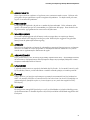
CAUTION
Cautions warn the user about how to prevent damage to hardware or loss of data.
NOTE
Notes call attention to important information.

Intel Desktop Board D945GRW Product Guide
iv
Terminology
The table below gives descriptions to some common terms used in the product guide.
Term Description
GB Gigabyte (1,073,741,824 bytes)
GHz Gigahertz (one billion hertz)
KB Kilobyte (1024 bytes)
MB Megabyte (1,048,576 bytes)
Mbit Megabit (1,048,576 bits)
MHz Megahertz (one million hertz)
Box Contents
• Intel Desktop Board D945GRW
• I/O shield
• One ATA-66/100 cable
• One locking Serial ATA cable
• Quick Reference poster
• Configuration and battery caution statement label
• Intel
®
Express Installer driver CD-ROM
• Intel Express Installer software CD-ROM

v
Contents
1 Desktop Board Features
Supported Operating Systems ............................................................................................11
Desktop Board Components ...............................................................................................12
Processor............................................................................................................................14
Main Memory ......................................................................................................................15
Intel
®
945G Express Chipset...............................................................................................16
Graphics Subsystem ...........................................................................................................16
Audio Subsystem ................................................................................................................16
Input/Output (I/O) Controller ................................................................................................17
LAN Subsystem ..................................................................................................................17
LAN Subsystem Software...........................................................................................17
RJ-45 LAN Connector LEDs.......................................................................................18
Hi-Speed USB 2.0 Support..................................................................................................18
Enhanced IDE Interface ......................................................................................................19
Serial ATA...........................................................................................................................19
Expandability.......................................................................................................................19
BIOS ...................................................................................................................................20
Serial ATA and IDE Auto Configuration ......................................................................20
PCI and PCI Express Auto Configuration ...................................................................20
Security Passwords....................................................................................................20
Chassis Intrusion.................................................................................................................20
Power Management Features .............................................................................................21
ACPI...........................................................................................................................21
Power Connectors......................................................................................................21
Fan Connectors..........................................................................................................21
Fan Speed Control (Intel
®
Precision Cooling Technology)..........................................21
Suspend to RAM (Instantly Available PC Technology) ...............................................22
Wake from USB..........................................................................................................23
Wake from PS/2 Keyboard/Mouse..............................................................................23
PME# Wakeup Support ..............................................................................................23
Speaker...............................................................................................................................23
Battery.................................................................................................................................23
Real-Time Clock..................................................................................................................23
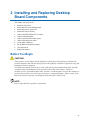
2 Installing and Replacing Desktop Board Components
Before You Begin................................................................................................................25
Installation Precautions .......................................................................................................26
Installation Instructions........................................................................................................26
Ensure Electromagnetic Compatibility (EMC) Compliance..........................................26
Chassis and Component Certifications.......................................................................27
Prevent Power Supply Overload.................................................................................27
Place Battery Marking ................................................................................................27
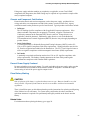
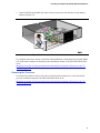
Installing the I/O Shield .......................................................................................................28
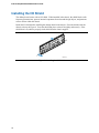
Installing and Removing the Desktop Board........................................................................29

Intel Desktop Board D945GRW Product Guide
vi
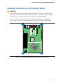
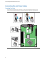
Installing and Removing a Processor ..................................................................................30
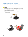
Installing a Processor .................................................................................................30
Installing the Thermal Module.....................................................................................33
Removing the Processor ............................................................................................35
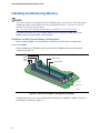
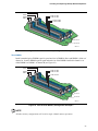
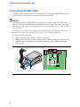
Installing and Removing Memory ........................................................................................36
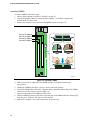
Installing DIMMs.........................................................................................................38
Removing DIMMs.......................................................................................................39
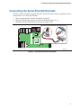
Connecting the IDE Cable...................................................................................................40
Connecting the Serial ATA (SATA) Cable ...........................................................................41
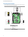
Connecting Internal Headers...............................................................................................42
Installing a Front Panel Audio Solution for Intel
®
High Definition Audio.......................43
Connecting the USB 2.0 Header.................................................................................44
Connecting the Front Panel Header ...........................................................................44
Connecting to the Flexible Audio System ............................................................................45
Connecting Fan and Power Cables .....................................................................................46
Connecting Fan Cables ..............................................................................................46
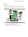
Connecting Power Cables ..........................................................................................47
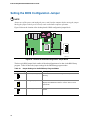
Setting the BIOS Configuration Jumper...............................................................................48
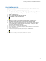
Clearing Passwords ............................................................................................................49
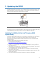
3 Updating the BIOS
Updating the BIOS with the Intel
®
Express BIOS Update Utility...........................................55
Updating the BIOS with the Iflash Memory Update Utility ....................................................56
Obtaining the BIOS Update File..................................................................................56
Updating the BIOS......................................................................................................56
Recovering the BIOS..................................................................................................57
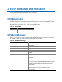
A Error Messages and Indicators
BIOS Beep Codes...............................................................................................................59
BIOS Error Messages .........................................................................................................59
B Regulatory Compliance
Safety Regulations ..............................................................................................................61
European Union Declaration of Conformity Statement ........................................................61
Product Ecology Statements ...............................................................................................63
Lead-Free Desktop Board ..........................................................................................66
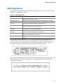
EMC Regulations ................................................................................................................67
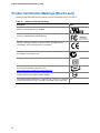
Product Certification Markings (Board Level) ......................................................................68

Contents
vii
Figures
1. Desktop Board D945GRW Components.......................................................................12
2. LAN Connector LEDs....................................................................................................18
3. Location of Standby Power Indicator.............................................................................22
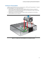
4. Installing the I/O Shield.................................................................................................28
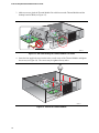
5. Desktop Board D945GRW Mounting Screw Hole Locations .........................................29
6. Lift Socket Lever...........................................................................................................30
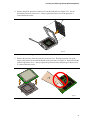
7. Lift the Load Plate and Don’t Touch the Socket Contacts .............................................30
8. Remove the Protective Socket Cover ...........................................................................31
9. Remove the Processor from the Protective Processor Cover/Do Not Touch.................31
10. Install Processor ...........................................................................................................32
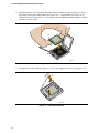
11. Close the Load Plate ....................................................................................................32
12. Position the Thermal Module Over the Mounting Holes ................................................33
13. Use Care Routing the Thermal Module Fan Cable........................................................34
14. Secure the Thermal Module..........................................................................................34
15. Connect the Thermal Module Fan Cable ......................................................................35
16. Dual Channel Memory Configuration Example 1...........................................................36
17. Dual Configuration Example 2 ......................................................................................37
18. Dual Configuration Example 3 ......................................................................................37
19. Installing a DIMM..........................................................................................................38
20. Connecting the IDE Cable ............................................................................................40
21. Connecting the Serial ATA Cable .................................................................................41
22. Internal Headers ...........................................................................................................42
23. Back Panel Audio Connectors ......................................................................................45
24. Location of Fan Headers...............................................................................................46
25. Connecting Power Supply Cables.................................................................................47
26. Location of the BIOS Configuration Jumper Block ........................................................48
27. Removing the Battery ...................................................................................................54
28. F2 Key ..........................................................................................................................55

Intel Desktop Board D945GRW Product Guide
viii
Tables
1. Feature Summary...........................................................................................................9
2. Desktop Board D945GRW Components.......................................................................13
3. Power Supply Requirements.........................................................................................14
4. Desktop Board D945GRW Memory Configurations ......................................................15
5. RJ-45 10/100/1000 Gigabit Ethernet LAN Connector LEDs ..........................................18
6. Front Panel Audio Header Signal Names for Intel High Definition Audio.......................43
7. AC ’97 Audio Header Signal Names .............................................................................43
8. USB 2.0 Header Signal Names.....................................................................................44
9. Front Panel Header Signal Names................................................................................44
10. Jumper Settings for the BIOS Setup Program Modes ...................................................48
11. Beep Codes..................................................................................................................59
12. BIOS Error Messages...................................................................................................59
13. Safety Regulations........................................................................................................61
14. Lead-Free Board Markings ...........................................................................................66
15. EMC Regulations..........................................................................................................67
16. Product Certification Markings ......................................................................................68

9
1 Desktop Board Features
This chapter briefly describes the main features of Intel
®
Desktop Board D945GRW. Table 1
summarizes the major features of the desktop board.
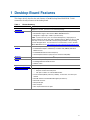
Table 1. Feature Summary
Form Factor
PicoBTX (10.5-inches x 8.0-inches)
Processor
Support for an Intel
®
processor in the LGA775 package
Main Memory
• Four 240-pin, 1.8 V SDRAM Dual Inline Memory Module (DIMM) sockets
• 667/533 MHz single or dual channel DDR2 SDRAM interface
• Designed to support up to 4 GB of system memory
NOTE: System resources (such as PCI and PCI Express*) require physical
memory address locations that reduce available memory addresses above 3 GB.
This may result in less than 4 GB of memory being available to the operating
system and applications. For the latest list of tested memory, refer to the Intel
World Wide Web site at: http://support.intel.com/support/motherboards/desktop/
Chipset
Intel
®
945G Express Chipset consisting of:
• Intel
®
82945G Graphics and Memory Controller Hub (GMCH) with Direct
Media Interface
• Intel
®
82801GB I/O Controller Hub (ICH7)
• Serial Peripheral Interface (SPI) Flash or Firmware Hub (FWH)
Graphics
Intel 945G Express Chipset with Intel
®
Graphics Media Accelerator 950
Audio
• Intel 945G Express Chipset
• Intel
®
High Definition Audio interface
• Realtek* codec
Expansion Capabilities
• One PCI Express x16 connector
Peripheral Interfaces
• Up to eight USB 2.0 ports
⎯ Six ports routed to the back panel
⎯ Two ports routed to an onboard USB header
• Two Serial ATA (SATA) channels (3.0 Gb/s), via the ICH7, one device per
channel
• One IDE interface with ATA-66/100 support (two devices)
• One VGA connector
• One parallel port
• One serial port
• PS/2* keyboard and mouse ports
continued

Intel Desktop Board D945GRW Product Guide
10
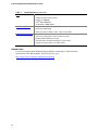
Table 1. Feature Summary (continued)
BIOS
• Intel
®
Platform Innovation Framework for extensible firmware interface
• 4 Mbit symmetrical flash memory
• Support for SMBIOS
• Intel
®
Rapid BIOS Boot
• Intel
®
Express BIOS Update
Power Management
• Support for Advanced Configuration and Power Interface (ACPI)
• Suspend to RAM (STR)
• Wake on USB, PCI Express, PS/2, LAN, and front panel
Hardware Management Hardware monitor with:
• Three fan sensing inputs used to monitor fan activity
• Remote diode temperature sensing
• Intel
®
Precision Cooling Technology fan speed control
• Voltage sensing to detect out of range values
Related Links:
For more information about desktop board D945GRW, including the Technical Product
Specification (TPS), BIOS updates, and device drivers, go to:
http://support.intel.com/support/motherboards/desktop/

Desktop Board Features
11
Supported Operating Systems
The desktop board supports the following operating systems:
• Microsoft Windows* 2000
• Microsoft Windows XP Professional
• Microsoft Windows XP Professional x64 Edition
• Microsoft Windows XP Home
• Microsoft Windows XP Media Center Edition 2005

Intel Desktop Board D945GRW Product Guide
12
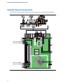
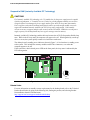
Desktop Board Components
Figure 1 shows the approximate location of the major components on desktop board D945GRW.
OM18149
L
P
O
N
M
Channel A, DIMM 0
K
I
H
F
G
D
E
J
Line In
A CB
Channel A, DIMM 1
Channel B, DIMM 1
Channel B, DIMM 0
Figure 1. Desktop Board D945GRW Components

Desktop Board Features
13
Table 2. Desktop Board D945GRW Components
Label Description
A Chassis intrusion header
B Serial ATA connectors
C Hi-speed USB 2.0 headers
D Main power connector (2x12)
E PCI Express x16 connector
F BIOS configuration jumper block
G Speaker
H Processor socket
I Alternate power LED header
J Front panel header
K Processor fan header (4-pin, fan speed control)
L 12 V processor core voltage connector (2x2)
M Rear chassis fan header 1 (3-pin, fan speed control)
N Battery
O IDE connector
P Front panel audio header
Related Links:
Go to the following links for more information about:
• Desktop board D945GRW
http://www.intel.com/design/motherbd
http://support.intel.com/support/motherboards/desktop
• Supported processors
http://support.intel.com/support/motherboards/desktop
• Audio software and utilities
http://www.intel.com/design/motherbd
• LAN software and drivers
http://www.intel.com/design/motherbd

Intel Desktop Board D945GRW Product Guide
14
Processor
CAUTION
Failure to use the appropriate power supply (below) and/or not connecting the 12 V (2x2) power
connector to the desktop board may result in damage to the board, or the system may not function
properly.
Table 3. Power Supply Requirements
Platform Compatibility Guide Power Supply Requirements
05A 12V2 rating of 13 A continuous and 16.5 A peak current for 10 ms
04A ATX12V (version 2.0 or greater) compliant power supply
Desktop board D945GRW supports an Intel processor in the LGA775 package. Processors are not
included with the desktop board and must be purchased separately. The processor connects to the
desktop board through the LGA775 socket.
The supported processors list for desktop board D945GRW is located on the web at:
http://support.intel.com/support/motherboards/desktop/
Related Links:
Go to the following links or pages for more information about:
• Instructions on installing or upgrading the processor, page
30 in Chapter 2
• The location of the two power connectors, page
46 in Chapter 2

Desktop Board Features
15
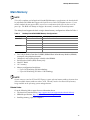
Main Memory
NOTE
To be fully compliant with all applicable Intel
®
SDRAM memory specifications, the board should
be populated with DIMMs that support the Serial Presence Detect (SPD) data structure. If your
memory modules do not support SPD, you will see a notification to this effect on the screen at
power up. The BIOS will attempt to configure the memory controller for normal operation.
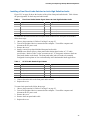
The desktop board supports the dual or single channel memory configurations defined in Table 4.
Table 4. Desktop Board D945GRW Memory Configurations
Memory Speed FSB Frequency (MHz) Memory Speed (MHz)
1066 667
800 667
DDR2-667
533 533
1066 533
800 533
DDR2-533
533 533
• Four 240-pin Double Data Rate 2 (DDR2) SDRAM Dual Inline Memory Module (DIMMs)
connectors with gold-plated contacts
• Unbuffered, non-registered single or double-sided DIMMs
• Serial Presence Detect (SPD) memory only
• Non-ECC RAM
• 1.8 V memory
• Memory configuration listed below:
⎯ Up to 2.0 GB utilizing 256 Mb technology
⎯ Up to 4.0 GB utilizing 512 Mb or 1 Gb technology
NOTE
System resources (such as PCI and PCI Express) require physical memory address locations that
reduce available memory addresses above 3 GB. This may result in less than 4 GB of memory
being available to the operating system and applications.
Related Links:
Go to the following links or pages for more information about:
• The latest list of tested memory,
http://support.intel.com/support/motherboards/desktop/
• SDRAM specifications,
http://www.intel.com/technology/memory/
• Installing memory, page
36 in Chapter 2

Intel Desktop Board D945GRW Product Guide
16
Intel
®
945G Express Chipset
The Intel 945G Express Chipset consists of the following devices:
• Intel 82945G Graphics and Memory Controller Hub (GMCH) with Digital Media Interface
• Intel 82801GB I/O Controller Hub (ICH7)
• Serial Peripheral Interface (SPI) Flash or Firmware Hub (FWH)
Related Link:
Go to the following link for more information about the Intel 945G Express Chipset:
http://developer.intel.com/design/nav/pcserver.htm
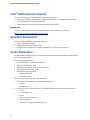
Graphics Subsystem
Desktop board D945GRW includes the following:
• Intel 945G Express Chipset
• Intel Graphics Media Accelerator 950
• PCI Express x16 connector for graphics expansion via a PCI Express riser card
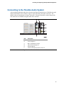
Audio Subsystem
Desktop board D945GRW includes a flexible 8-channel audio subsystem based on an Intel High
Definition Audio interface:
The audio subsystem features:
• Intel 82801GB I/O Controller Hub (ICH7)
• Realtek ALC880 audio codec
• Impedance sensing capability for jack re-tasking
• S/N (signal-to-noise) ratio: 95 dB
• Microphone input supporting:
⎯ Stereo microphone
⎯ Microphone boost
The subsystem includes the following connectors:
• Front panel audio connector, including functionality for:
⎯ Line out
⎯ Microphone in
• Back panel audio connectors that are configurable through the drivers of the audio devices:
⎯ Line in
⎯ Front left/right out
⎯ Mic in
⎯ Side surround left/right out
⎯ Rear left/right out
⎯ Center/Low Frequency Effects (LFE) out

Desktop Board Features
17
Related Links:
Go to the following link or pages for more information about:
• Audio drivers and utilities
http://support.intel.com/support/motherboards/desktop/
• Installing the front panel audio solution, page
43 in Chapter 2
• The location of audio connectors,
Figure 23 on page 45
Input/Output (I/O) Controller
The super I/O controller features the following:
• Low pin count (LPC) interface
• One serial port
• One parallel port with Extended Capabilities Port (ECP) and Enhanced Parallel Port
(EPP) support
• Serial IRQ interface compatible with serialized IRQ support for PCI systems
• PS/2-style mouse and keyboard interfaces
• Interface for one 1.2 MB or 1.44 MB diskette drive
• Intelligent power management, including a programmable wake up event interface
• PCI power management support
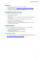
LAN Subsystem
The LAN subsystem, with Intel 82801GB (ICH7) provides the following functions:
• 10/100/1000 Gigabit Ethernet LAN (Intel
®
82573L)
• Support for RJ-45 connector with status indicator LEDs
• Programmable transit threshold
• Configurable EEPROM that contains the MAC address
LAN Subsystem Software
For LAN software and drivers, refer to the D945GRW link on Intel’s World Wide Web site at:
http://support.intel.com/support/motherboards/desktop

Intel Desktop Board D945GRW Product Guide
18
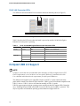
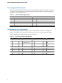
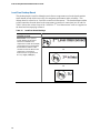
RJ-45 LAN Connector LEDs
Two LEDs are built into the RJ-45 LAN connector located on the back panel (see Figure 2).
Figure 2. LAN Connector LEDs
Table 5 describes the LED states when the board is powered up and the 10/100/1000 Gigabit
Ethernet LAN subsystem is operating.
Table 5. RJ-45 10/100/1000 Gigabit Ethernet LAN Connector LEDs
LED LED Color LED State Indicates
Left (A) Off LAN link is not established
Green
On LAN link is established
Blinking LAN activity is occurring
N/A Off 10 Mb/s data rate
Green On 100 Mb/s data rate
Right (B)
Yellow On 1000 Mb/s data rate
Hi-Speed USB 2.0 Support
NOTE
Computer systems that have an unshielded cable attached to a USB port might not meet FCC
Class B requirements, even if no device or a low-speed USB device is attached to the cable.
Use a shielded cable that meets the requirements for a full-speed USB device.
The desktop board supports up to eight USB 2.0 ports via ICH7; six ports routed to the back
panel and two routed to one internal USB 2.0 header. USB 2.0 ports are backward compatible with
USB 1.1 devices. USB 1.1 devices will function normally at USB 1.1 speeds.
USB 2.0 support requires both an operating system and drivers that fully support USB 2.0 transfer
rates. Disabling Hi-Speed USB in the BIOS reverts all USB 2.0 ports to USB 1.1 operation. This
may be required to accommodate operating systems that do not support USB 2.0.

Desktop Board Features
19
Enhanced IDE Interface
The ICH7’s IDE interface handles the exchange of information between the processor and
peripheral devices like hard disks, CD-ROM drives, and Iomega Zip* drives inside the computer.
The interface supports:
• Up to two IDE devices (such as hard drives)
• ATAPI-style devices (such as CD-ROM drives)
• Older PIO Mode devices
• Ultra DMA-33 and ATA-66/100 protocols
Serial ATA
The desktop board supports two Serial ATA channels (3.0 Gb/s) via ICH7, connecting one device
per channel.
Expandability
For system expansion, the desktop board provides the following:
• One PCI Express x16 connector

Intel Desktop Board D945GRW Product Guide
20
BIOS
The BIOS provides the Power-On Self-Test (POST), the BIOS Setup program, the PCI/PCI
Express and IDE auto-configuration utilities, and the video BIOS. The BIOS is stored in the Serial
Peripheral Interface (SPI) Flash or the Firmware Hub.
The BIOS can be updated by following the instructions on page
55 in Chapter 3.
Serial ATA and IDE Auto Configuration
If you install a Serial ATA or IDE device (such as a hard drive) in your computer, the auto-
configuration utility in the BIOS automatically detects and configures the device for your computer.
You do not need to run the BIOS Setup program after installing a Serial ATA or IDE device. You
can override the auto-configuration options by specifying manual configuration in the BIOS Setup
program.
PCI and PCI Express Auto Configuration
If you install a PCI/PCI Express add-in card in your computer, the PCI/PCI Express auto-
configuration utility in the BIOS automatically detects and configures the resources (IRQs, DMA
channels, and I/O space) for that add-in card. You do not need to run the BIOS Setup program after
you install a PCI/PCI Express add-in card.
Security Passwords
The BIOS includes security features that restrict whether the BIOS Setup program can be accessed
and who can boot the computer. A supervisor password and a user password can be set for the
BIOS Setup and for booting the computer, with the following restrictions:
• The supervisor password gives unrestricted access to view and change all Setup options. If
only the supervisor password is set, pressing <Enter> at the password prompt of Setup gives the
user restricted access to Setup.
• If both the supervisor and user passwords are set, you must enter either the supervisor password
or the user password to access Setup. Setup options are then available for viewing and
changing depending on whether the supervisor or user password was entered.
• Setting a user password restricts who can boot the computer. The password prompt is
displayed before the computer is booted. If only the supervisor password is set, the computer
boots without asking for a password. If both passwords are set, you can enter either password
to boot the computer.
Related Links:
For instructions on resetting the password, see
Clearing Passwords on page 49.
Chassis Intrusion
The board supports a chassis security feature that detects if the chassis cover has been removed.
The security feature uses a mechanical switch on the chassis that can be connected to the chassis
intrusion header on the desktop board. See
Figure 22 on page 42 for the location of the chassis
intrusion header.
La pagina si sta caricando...
La pagina si sta caricando...
La pagina si sta caricando...
La pagina si sta caricando...
La pagina si sta caricando...
La pagina si sta caricando...
La pagina si sta caricando...
La pagina si sta caricando...
La pagina si sta caricando...
La pagina si sta caricando...
La pagina si sta caricando...
La pagina si sta caricando...
La pagina si sta caricando...
La pagina si sta caricando...
La pagina si sta caricando...
La pagina si sta caricando...
La pagina si sta caricando...
La pagina si sta caricando...
La pagina si sta caricando...
La pagina si sta caricando...
La pagina si sta caricando...
La pagina si sta caricando...
La pagina si sta caricando...
La pagina si sta caricando...
La pagina si sta caricando...
La pagina si sta caricando...
La pagina si sta caricando...
La pagina si sta caricando...
La pagina si sta caricando...
La pagina si sta caricando...
La pagina si sta caricando...
La pagina si sta caricando...
La pagina si sta caricando...
La pagina si sta caricando...
La pagina si sta caricando...
La pagina si sta caricando...
La pagina si sta caricando...
La pagina si sta caricando...
La pagina si sta caricando...
La pagina si sta caricando...
La pagina si sta caricando...
La pagina si sta caricando...
La pagina si sta caricando...
La pagina si sta caricando...
La pagina si sta caricando...
La pagina si sta caricando...
La pagina si sta caricando...
La pagina si sta caricando...
-
 1
1
-
 2
2
-
 3
3
-
 4
4
-
 5
5
-
 6
6
-
 7
7
-
 8
8
-
 9
9
-
 10
10
-
 11
11
-
 12
12
-
 13
13
-
 14
14
-
 15
15
-
 16
16
-
 17
17
-
 18
18
-
 19
19
-
 20
20
-
 21
21
-
 22
22
-
 23
23
-
 24
24
-
 25
25
-
 26
26
-
 27
27
-
 28
28
-
 29
29
-
 30
30
-
 31
31
-
 32
32
-
 33
33
-
 34
34
-
 35
35
-
 36
36
-
 37
37
-
 38
38
-
 39
39
-
 40
40
-
 41
41
-
 42
42
-
 43
43
-
 44
44
-
 45
45
-
 46
46
-
 47
47
-
 48
48
-
 49
49
-
 50
50
-
 51
51
-
 52
52
-
 53
53
-
 54
54
-
 55
55
-
 56
56
-
 57
57
-
 58
58
-
 59
59
-
 60
60
-
 61
61
-
 62
62
-
 63
63
-
 64
64
-
 65
65
-
 66
66
-
 67
67
-
 68
68


Intel D945GRW - Desktop Board Motherboard Manuale utente
- Categoria
- Schede madri
- Tipo
- Manuale utente
in altre lingue
Documenti correlati
-
Intel Musical Toy Instrument D945GNT/D945GTP Manuale utente
-
Intel BOXD945PSNLK Manuale utente
-
-
-
-
-
eMachines D845GVSRL Manuale utente
-
-
-