Motorola MOTOSLVR L72 Manuale utente
- Categoria
- Cellulari
- Tipo
- Manuale utente
Questo manuale è adatto anche per

Level 1 and 2 Service Manual
6809510A66-O
Wireless Telephone
GSM 850/900/1800/1900 MHz GPRS/EDGE
MOTOSLVR
tm
L9/L72

MOTOROLA and the Stylized M Logo are registered in the US Patent & Trademark Office.
All other product or service names are the property of their respective owners.
The Bluetooth trademarks are owned by their proprietor and used by Motorola, Inc. under license.
© Motorola, Inc. 2007.
All rights reserved.
Mobile Devices Business,
Sawgrass International Concourse
789 International Parkway
Room S2C
Sunrise, FL 33325-6220

6809510A66-O October 12, 2006 3
Level 1 and 2 Service Manual Contents
Contents
Contents . . . . . . . . . . . . . . . . . . . . . . . . . . . . . . . . . . . . . . . . . . . . . . . . . . . . . . . . . . . . . . . . . . . . . . . . . . . . . . . . . . . . 3
Introduction . . . . . . . . . . . . . . . . . . . . . . . . . . . . . . . . . . . . . . . . . . . . . . . . . . . . . . . . . . . . . . . . . . . . . . . . . . . . . . . . . 5
Product Identification . . . . . . . . . . . . . . . . . . . . . . . . . . . . . . . . . . . . . . . . . . . . . . . . . . . . . . . . . . . . . . . . . . . 5
Product Names . . . . . . . . . . . . . . . . . . . . . . . . . . . . . . . . . . . . . . . . . . . . . . . . . . . . . . . . . . . . . . . . . . . . . . . . 5
Regulatory Agency Compliance . . . . . . . . . . . . . . . . . . . . . . . . . . . . . . . . . . . . . . . . . . . . . . . . . . . . . . . . . . . 5
Computer Program Copyrights . . . . . . . . . . . . . . . . . . . . . . . . . . . . . . . . . . . . . . . . . . . . . . . . . . . . . . . . . . . 6
About this Service Manual . . . . . . . . . . . . . . . . . . . . . . . . . . . . . . . . . . . . . . . . . . . . . . . . . . . . . . . . . . . . . . . 6
Warranty Service Policy . . . . . . . . . . . . . . . . . . . . . . . . . . . . . . . . . . . . . . . . . . . . . . . . . . . . . . . . . . . . . . . . . 7
Parts Replacement . . . . . . . . . . . . . . . . . . . . . . . . . . . . . . . . . . . . . . . . . . . . . . . . . . . . . . . . . . . . . . . . . . . . . 7
Specifications . . . . . . . . . . . . . . . . . . . . . . . . . . . . . . . . . . . . . . . . . . . . . . . . . . . . . . . . . . . . . . . . . . . . . . . . . . . . . . 9
Product Overview . . . . . . . . . . . . . . . . . . . . . . . . . . . . . . . . . . . . . . . . . . . . . . . . . . . . . . . . . . . . . . . . . . . . . . . . . . . 11
Features . . . . . . . . . . . . . . . . . . . . . . . . . . . . . . . . . . . . . . . . . . . . . . . . . . . . . . . . . . . . . . . . . . . . . . . . . . . . . 11
General Operation . . . . . . . . . . . . . . . . . . . . . . . . . . . . . . . . . . . . . . . . . . . . . . . . . . . . . . . . . . . . . . . . . . . . . . . . . . . 13
Controls, Indicators, and Input/Output (I/O) Connectors . . . . . . . . . . . . . . . . . . . . . . . . . . . . . . . . . . . . . 13
Battery Function . . . . . . . . . . . . . . . . . . . . . . . . . . . . . . . . . . . . . . . . . . . . . . . . . . . . . . . . . . . . . . . . . . . . . . 15
Operation . . . . . . . . . . . . . . . . . . . . . . . . . . . . . . . . . . . . . . . . . . . . . . . . . . . . . . . . . . . . . . . . . . . . . . . . . . . . 16
Tools and Test Equipment . . . . . . . . . . . . . . . . . . . . . . . . . . . . . . . . . . . . . . . . . . . . . . . . . . . . . . . . . . . . . . . . . . . . 17
Disassembly . . . . . . . . . . . . . . . . . . . . . . . . . . . . . . . . . . . . . . . . . . . . . . . . . . . . . . . . . . . . . . . . . . . . . . . . . . . . . . . . 18
Removing and Replacing the Battery Cover . . . . . . . . . . . . . . . . . . . . . . . . . . . . . . . . . . . . . . . . . . . . . . . . 18
Removing and Replacing the Battery . . . . . . . . . . . . . . . . . . . . . . . . . . . . . . . . . . . . . . . . . . . . . . . . . . . . . 19
Removing and Replacing the SIM . . . . . . . . . . . . . . . . . . . . . . . . . . . . . . . . . . . . . . . . . . . . . . . . . . . . . . . . 20
Removing and Replacing the Antenna Cap . . . . . . . . . . . . . . . . . . . . . . . . . . . . . . . . . . . . . . . . . . . . . . . . . 21
Removing and Replacing the Transceiver PC Board Shield . . . . . . . . . . . . . . . . . . . . . . . . . . . . . . . . . . . 22
Removing and Replacing the Transceiver PC Board . . . . . . . . . . . . . . . . . . . . . . . . . . . . . . . . . . . . . . . . . 23
Removing and Replacing the Camera Assembly . . . . . . . . . . . . . . . . . . . . . . . . . . . . . . . . . . . . . . . . . . . . . 26
Removing and Replacing the Front Housing . . . . . . . . . . . . . . . . . . . . . . . . . . . . . . . . . . . . . . . . . . . . . . . . 28
Removing and Replacing the Keypad . . . . . . . . . . . . . . . . . . . . . . . . . . . . . . . . . . . . . . . . . . . . . . . . . . . . . 29
Removing and Replacing the Keypad PC Board . . . . . . . . . . . . . . . . . . . . . . . . . . . . . . . . . . . . . . . . . . . . . 30
Removing and Replacing the Antenna . . . . . . . . . . . . . . . . . . . . . . . . . . . . . . . . . . . . . . . . . . . . . . . . . . . . 31
Removing and Replacing the Display Module . . . . . . . . . . . . . . . . . . . . . . . . . . . . . . . . . . . . . . . . . . . . . . . 32
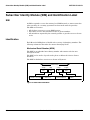
Subscriber Identity Module (SIM) and Identification Label . . . . . . . . . . . . . . . . . . . . . . . . . . . . . . . . . . . . . . . . . . 34
SIM . . . . . . . . . . . . . . . . . . . . . . . . . . . . . . . . . . . . . . . . . . . . . . . . . . . . . . . . . . . . . . . . . . . . . . . . . . . . . . . . 34
Identification . . . . . . . . . . . . . . . . . . . . . . . . . . . . . . . . . . . . . . . . . . . . . . . . . . . . . . . . . . . . . . . . . . . . . . . . . 34
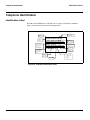
Telephone Identification . . . . . . . . . . . . . . . . . . . . . . . . . . . . . . . . . . . . . . . . . . . . . . . . . . . . . . . . . . . . . . . . . . . . . . 36
Identification Label . . . . . . . . . . . . . . . . . . . . . . . . . . . . . . . . . . . . . . . . . . . . . . . . . . . . . . . . . . . . . . . . . . . . 36
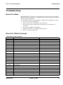
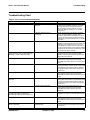
Troubleshooting . . . . . . . . . . . . . . . . . . . . . . . . . . . . . . . . . . . . . . . . . . . . . . . . . . . . . . . . . . . . . . . . . . . . . . . . . . . . 37
Manual Test Mode . . . . . . . . . . . . . . . . . . . . . . . . . . . . . . . . . . . . . . . . . . . . . . . . . . . . . . . . . . . . . . . . . . . . 37
Manual Test Mode Commands . . . . . . . . . . . . . . . . . . . . . . . . . . . . . . . . . . . . . . . . . . . . . . . . . . . . . . . . . . . 37
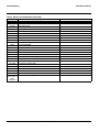
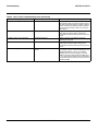
Troubleshooting Chart . . . . . . . . . . . . . . . . . . . . . . . . . . . . . . . . . . . . . . . . . . . . . . . . . . . . . . . . . . . . . . . . . 39
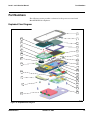
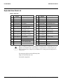
Part Numbers . . . . . . . . . . . . . . . . . . . . . . . . . . . . . . . . . . . . . . . . . . . . . . . . . . . . . . . . . . . . . . . . . . . . . . . . . . . . . . . 41
Exploded View Diagram . . . . . . . . . . . . . . . . . . . . . . . . . . . . . . . . . . . . . . . . . . . . . . . . . . . . . . . . . . . . . . . . 41
Exploded View Parts List . . . . . . . . . . . . . . . . . . . . . . . . . . . . . . . . . . . . . . . . . . . . . . . . . . . . . . . . . . . . . . 42
Accessories . . . . . . . . . . . . . . . . . . . . . . . . . . . . . . . . . . . . . . . . . . . . . . . . . . . . . . . . . . . . . . . . . . . . . . . . . . . 43
Related Publications . . . . . . . . . . . . . . . . . . . . . . . . . . . . . . . . . . . . . . . . . . . . . . . . . . . . . . . . . . . . . . . . . . . 46
Programming: Software Upgrade and Flexing . . . . . . . . . . . . . . . . . . . . . . . . . . . . . . . . . . . . . . . . . . . . . . 46
Index . . . . . . . . . . . . . . . . . . . . . . . . . . . . . . . . . . . . . . . . . . . . . . . . . . . . . . . . . . . . . . . . . . . . . . . . . . . . . . . . . . . . . . 47
1 and 2
6809510A66-O
MOTOSLVR L9/L72
Contents

4 October 12, 2006 6809510A66-O
Contents MOTOSLVR L9/L72

6809510A66-O October 12, 2006 5
Level 1 and 2 Service Manual Introduction
Introduction
Motorola
®
Inc. maintains a worldwide organization that is dedicated to provide
responsive, full-service customer support. Motorola products are serviced by an
international network of company-operated product-care centers as well as
authorized independent service firms.
Available on a contract basis, Motorola Inc. offers comprehensive maintenance
and installation programs that enable customers to meet requirements for
reliable, continuous communications.
To learn more about the wide range of Motorola service programs, contact your
local Motorola products representative or the nearest Customer Service Manager.
Product Identification
Motorola products are identified by the model number on the housing. Use the
entire model number when inquiring about the product. Numbers are also
assigned to chassis and kits. Use these numbers when requesting information or
ordering replacement parts.
Product Names
Product names are listed on the front cover. Product names are subject to change
without notice. Some product names, as well as some frequency bands, are
available only in certain markets.
Regulatory Agency Compliance
This device complies with Part 15 of the FCC Rules. Operation is subject to the
following conditions:
• This device may not cause any harmful interference, and
• must accept interference received, including interference that may cause
undesired operation.
This class B device also complies with all requirements of the Canadian
Interference-Causing Equipment Regulations (ICES-003).
Cet appareil numérique de la classe B respecte toutes les exigences du Règlement
sur le matériel brouilleur du Canada.
1 and 2
6809510A66-O
MOTOSLVR L9/L72

6 October 12, 2006 6809510A66-O
Introduction MOTOSLVR L9/L72
Computer Program Copyrights
The Motorola products described in this manual may include Motorola computer
programs stored in semiconductor memories or other media that are copyrighted
with all rights reserved worldwide to Motorola. Laws in the United States and
other countries preserve for Motorola, Inc. certain exclusive rights to the
copyrighted computer programs, including the exclusive right to copy, reproduce,
modify, decompile, disassemble, and reverse-engineer the Motorola computer
programs in any manner or form without Motorola's prior written consent.
Furthermore, the purchase of Motorola products shall not be deemed to grant
either directly or by implication, estoppel, or otherwise, any license or rights
under the copyrights, patents, or patent applications of Motorola, except for a
nonexclusive license to use the Motorola product and the Motorola computer
programs with the Motorola product.
About this Service Manual
Using this service manual and the suggestions contained in it assures proper
installation, operation, and maintenance of wireless telephones. Refer questions
about this manual to the nearest Customer Service Manager.
Audience
This manual aids service personnel in testing and repairing of wireless
telephones. Service personnel should be familiar with electronic assembly, testing,
and troubleshooting methods, and with the operation and use of associated test
equipment.
Use of this manual assures proper installation, operation, and maintenance of
Motorola products and equipment. It contains all service information required for
the equipment described and is current as of the printing date.
Scope
The scope of this manual is to provide basic information relating to wireless
telephones, and provide procedures and processes for repairing the phones at
Level 1 and 2 service centers including:
•Unit swap out
• Repairing of mechanical faults
• Basic modular troubleshooting
•Testing and verification of phone functionality
• Initiate warranty claims and send faulty modules to Level 3 or 4 repair
centers

6809510A66-O October 12, 2006 7
Level 1 and 2 Service Manual Introduction
Conventions
Special characters and typefaces, listed and described below, are used in this
manual to emphasize certain types of information.
Warranty Service Policy
This product is sold with the standard 12-month warranty terms and conditions.
Accidental damage, misuse, and extended warranties offered by retailers are not
supported under warranty. Non-warranty repairs are available at agreed fixed
repair prices.
Out of Box Failure Policy
The standard out of box failure criteria applies. Customer phones that fail very
early on after the date of sale, are to be returned to Manufacturing for root-cause
analysis, to guard against epidemic criteria. Manufacturing will bear the costs of
early life failure.
Product Support
Customer’s original phone will be repaired but not refurbished as standard.
Appointed Motorola Service Hubs will perform warranty and non-warranty field
service for level 2 (assemblies) and level 3 (limited PCB component). The Motorola
High Technology Centers will perform level 4 (full component) repairs.
Customer Support
Customer support is available through dedicated Call Centers and in-country help
desks. Product Service training should be arranged through the local Motorola
Support Center.
Parts Replacement
When ordering replacement parts or equipment, include the Motorola part
number and description used in the service manual.
When the Motorola part number of a component is not known, use the product model
number or other related major assembly along with a description of the related
➧
Note: Emphasizes additional information pertinent to the subject
matter.
G
Caution: Emphasizes information about actions that may result in
equipment damage.
E
Warning: Emphasizes information about actions that may result in
personal injury.
P
Keys to be pressed are represented graphically. For example, instead of “Press
the End key”, you will see “Press
P”.

8 October 12, 2006 6809510A66-O
Introduction MOTOSLVR L9/L72
major assembly and of the component in question.
In the U.S.A., to contact Motorola, Inc. on your TTY, call: 800-793-7834.
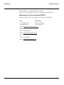
Replacement Parts Service Division (RPSD)
Order replacement parts, test equipment, and manuals from RPSD.
U.S.A. Outside U.S.A.
Phone: 800-422-4210 Phone: 847-538-8023
FAX: 800-622-6210 FAX: 847-576-3023
Website: http://businessonline.motorola.com
EMEA
Phone:
+49 461 803 1404
Website: http://emeaonline.motorola.com
Asia
Phone:
+65 648 62995
Website: http://asiaonline.motorola.com

6809510A66-O October 12, 2006 9
Level 1 and 2 Service Manual Specifications
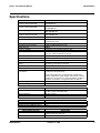
Specifications
General Function Specification
Frequency Range GSM 850
824-849 MHz Tx
869-894 MHz Rx
Frequency Range GSM 900
880-915 MHz Tx (with EGSM)
925-960 MHZ Rx
Frequency Range DCS 1800
1710-1785 MHz Tx
1805-1880 MHz Rx
Frequency Range PCS 1900
1850-1910 MHz Tx
1930-1990 MHz Rx
Channel Spacing 200 kHz
Channels 174 EGSM, 374 DCS, 374 PCS, 124 GSM 850 carriers with
8 channels per carrier
Modulation GSMK / 8- PSK (EDGE)
Transmitter Phase Accuracy 5 Degrees RMS, 20 Degrees peak
Duplex Spacing 45 MHz
Frequency Stability ± 0.10 ppm of the downlink frequency (Rx)
Operating Voltage +3.3V dc to +4.2V dc (battery)
+4 V dc to +5.6V dc (external connector)
Transmit Current Drain 90~280 mA average talk current drain
Stand-by Current drain 3.2 mA (DRX2), 2.2 mA (DXR9) typical
Temperature Range -10° C to +55° C (+15° F to +130° F)
Dimensions, with 840 mAh Li Ion
battery
113.5mm x 49mm x 11.5mm
(4.6 inches x 1.9 inches x 0.4 inches)
Size (Volume) 59 cc (3.6 in
3
), with battery
Weight 96 grams (3.3 oz), with battery
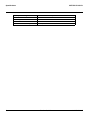
Battery Life, with standard 900 mAh
Li-Ion Battery
Talk time 210 to 400 minutes
Standby time 180 to 350 hours
All talk and standby times are approximate and depend on
network configuration, signal strength, and features selected.
Standby times are quoted as a range from DRX=2 to DRX=9.
Talk times are quoted as a range from DTX off to DTX on.
Battery Charge Time 4 hours to 90% of 900 mAh capacity
Alert volume Max 95 dB @5cm, 0.5 Watts input
Transmitter Function Specification
RF Power Output 32 dBm nominal GSM 850/900
29 dBm nominal GSM 1800/1900
Output Impedance 50 ohms nominal
Spurious Emissions -36 dBm from 0.1 to 1 GHz, -30 dBm from 1 to 4 GHz
Receiver Function Specification
Receive Sensitivity Better than -105 dBm
RX Bit Error Rate (100k bits) Type II < 2%
Speech Coding Function Specification
Speech Coding Type Regular pulse excitation/linear predictive coding with long term
prediction (RPE LPC with LTP)
Bit Rate 13.0 kbps

10 October 12, 2006 6809510A66-O
Specifications MOTOSLVR L9/L72
Frame Duration 20 ms
Block Length 260 bits
Classes Class 1 bits = 182 bits; Class 2 bits = 78 bits
Bit Rate with FEC Encoding 22.8 kbps
Speech Coding Function Specification

6809510A66-O October 12, 2006 11
Level 1 and 2 Service Manual Product Overview
Product Overview
MotoSLVR L9/L72 mobile telephones feature Global System for Mobile
communication (GSM) technology. The mobile telephone uses a simplified icon
and Graphical User Interface (GUI) for easier operation, allow Short Message
Service (SMS) text messaging, and include clock, alarm, datebook, and calculator
personal management tools. The telephones feature VibraCall vibrating alert and
a selection of ring tones. The MotoSLVR L9/L72 is a quad-band phone that allows
roaming within the 850, 900, 1800 and 1900MHz bands.
MotoSLVR L9/L72 telephones support EDGE/GPRS and SMS in addition to
traditional circuit switched transport technologies.
The telephones are made of polycarbonate plastic with a metal enclosure. The
display, camera, speaker, the 22-key keypad, transceiver Printed-circuit Board
(PCB), microphone, charger, headphone connectors, and power button are
contained within the candy bar form-factor housing. The 900 mAh Lithium Ion
(Li-Ion) battery provides up to 400 minutes of talk time with up to 350 hours of
standby time
1
. These telephones feature a 176 x 220 pixel display.
Features
The MotoSLVR L9/L72 telephones use advanced, self-contained, sealed, custom
integrated circuits to perform the complex functions required for GSM
communication. Aside from the space and weight advantage, microcircuits
enhance basic reliability, simplify maintenance, and provide a variety of
operational functions.
Features available in the MotoSLVR L9/L72 telephone include:
• Large 176 x 220 TFT display with 262K colors
• 2 Megapixel Camera 8x zoom,
• Video capture (15fps) and full screen video playback (15fps)
• Music player with MP3 and AAC support
• BlueTooth Class 2
• Software Skinning
• SyncML Device Management (Sync ML DM)
• Downloadable: Java apps, wallpaper, screensaver, ring tones (Midi/MP3)
• Integrated hands free speakerphone
• GPRS Class 10
• EDGE Class 10
• Push to Talk over cellular with GPRS
• SCREEN3 (Motorola/4th Pass server)
• Email POP3 & IMAP4
• 20MB internal memory, external Micro SD up to 2GB
Upon receipt of a call, the calling party’s phone number is compared to the
phonebook. If the number matches a phonebook entry, that name displays. If
1. All talk and standby times are approximate and depend on network configuration, signal strength, and features selected. Standby
times are quoted as a range from DRX=2 to DRX=9. Talk times are quoted as a range from DTX off to DTX on.

12 October 12, 2006 6809510A66-O
Product Overview MOTOSLVR L9/L72
there is no phonebook entry, the incoming phone number displays. If no caller
identification information is available, an incoming call message displays.
Personal Information Management
The MotoSLVR L9/L72 telephones contain a built-in datebook with alarm
reminders, message center, and a phonebook.
Other Features
Detailed descriptions of other features available for the MotoSLVR L9/L72
wireless telephones are in the appropriate User’s Guide listed in the Related
Publications section toward the end of this manual.
➧
User must subscribe to a caller line identification service through their service
provider.
➧
L9/L72 is the name used for this phone in the High Growth Markets (HGM),
North Asia & Latin America regions. L9/L72 is the name used for this phone in
the Europe region.

6809510A66-O October 12, 2006 13
Level 1 and 2 Service Manual General Operation
General Operation
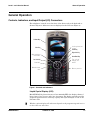
Controls, Indicators, and Input/Output (I/O) Connectors
The telephones’ controls are on the front of the device and on the keyboard as
shown in Figure 1. Indicator icons are displayed on the LCD (see Figure 2).
Liquid Crystal Display (LCD)
MotoSLVR L9/L72 phones feature a 176 x 220 262k TFT color display offering 7
lines of text, 1 line of icons, and 1 line of prompts. The display provides constant
graphical representations of battery capacity and signal strength, as well as the
real-time clock.
061507o
Figure 1. Controls and Indicators
➧
Whether a phone displays all indicators depends on the programming and services
to which the user subscribes.
Left Soft Key
Open and Select
menu items.
Volume Keys
Voice Key
Make & answer
calls.
Start radio.
Scroll up, down, left
or right.
Smart Key
Right Soft Key
Clear/Back Key
Turn on & off,
hang up, exit
menus.
Memory card slot.

14 October 12, 2006 6809510A66-O
General Operation MOTOSLVR L9/L72
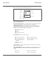
Figure 2 shows common icons displayed on the LCD.
1 Signal Strength Indicator – Vertical bars show the strength of the network
connection. You can’t make or receive calls when 1 or 0 appears.
2 EDGE/GPRS Indicator – Shows when your phone is using a high-speed
Enhanced Data for GSM Evolution (EDGE) or General Packet Radio Service
(GPRS) network connection. Indicators can include:
3 Data Indicator – Shows connection status.
4 Roam Indicator – Shows W when your phone is seeking or using a network
outside your home network.
5 Active Line Indicator – Shows h to indicate an active call, or g to indicate
when call forwarding is on. Indicators for dual-line-enabled SIM cards can
include:
050206o
Figure 2. Display Idle Screen
H
GPRS PDP context active
oe EDGE
B GPRS packet data available
L secure packet data transfer K unsecure packet data transfer
N secure application connection M unsecure application connection
S secure Circuit Switch Data
(CSD) call
T unsecure CSD call
O Bluetooth™ connection
is active
f line 1 active i line 1 active, call forward on
e line 2 active j line 2 active, call forward on
E
+
U
040079b
6.
Active Line
7.
Message
8.
Ring Style
9.
Battery
Level
5.
Roam
3.
PTT
2.
GPRS
1.
Signal
Strength
Service Provider
12:00
News and graphics from
your Service Provider
Setup Home Message
4.
Bluetooth

6809510A66-O October 12, 2006 15
Level 1 and 2 Service Manual General Operation
6 Messaging Presence Indicator – Shows when Instant Messaging (IM) is
active. Indicators can include:
When a Java™ application is active, z can show here.
If you set a reminder for a datebook event,l can show here.
7 Message Indicator – Shows when you receive a new message. Indicators can
include:
8 Ring Style Indicator – Shows the ring style setting.
9 Battery Level Indicator – Vertical bars show the battery charge level.
Recharge the battery when your display shows Low Battery.
Battery Function
Battery Charge Indicator
The telephone displays a battery charge indicator icon in the idle screen to
indicate the battery charge level. The gauge shows 4 levels: 100%, 50%, 20%, and
low battery.
Battery Removal
Removing the battery causes the phone to shut down immediately and loose any
pending work. For example, (partially entered phonebook entries or outgoing
messages).
q IM active s invisible to IM
r busy t offline
É text message Ë voice message
è voice & text message
é IM message
õ loud ring Ì vibrate & ring
ô soft ring ö vibrate then ring
Î vibrate Í silent
E
All batteries can cause property damage and/or bodily injury such as burns if a
conductive material such as jewelry, keys, or beaded chains touch exposed terminals.
The conductive material may complete an electrical circuit (short circuit) and
become quite hot. Exercise care when handling any charged battery, particularly
when placing it inside a pocket, purse, or other container with metal objects.

16 October 12, 2006 6809510A66-O
General Operation MOTOSLVR L9/L72
Operation
For detailed operating instructions, refer to the appropriate User’s Guide listed in
the Related Publications section toward the end of this manual.
G
If the battery is removed while receiving a message, the message is lost.
➧
To ensure proper memory retention, turn the phone OFF before removing the
battery. Immediately replace the old battery with a fresh battery.

6809510A66-O October 12, 2006 17
Level 1 and 2 Service Manual Tools and Test Equipment
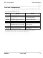
Tools and Test Equipment
This section describes how to disassemble MotoSLVR L9/L72 telephones. Table 1
lists the tools and test equipment used. Use either the listed items or equivalents.
Table 1. General Test Equipment and Tools
Motorola
Part Number
1
Description Application
See Table 6. Charger Used to charge battery and power phone.
0180386A82
Antistatic Mat Kit (includes 66-80387A95 antistatic
mat, 66-80334B36 ground cord, and 42-80385A59
wrist band)
Provides protection from damage to phone caused
by electrostatic discharge (ESD).
6680388B67 Disassembly Tool, plastic with flat and pointed
ends (manual opening tool)
Used during assembly/disassembly.
6680388B01 Tweezers, plastic Used during assembly/disassembly.
RSX4043-A Torque Driver Used to remove and replace screws.
—
Torque Driver Bits T3, and T6 Plus, Apex 440-5IP
Torx Plus or equivalent
Used with torque driver.
HP34401A
2
Digital Multimeter Used to measure battery voltage.
W.FL-LP-IN Coaxial cable connector removal tool
Used to attach or remove coaxial cable connector
to/from circuit board.
1. To order in North America, contact Motorola Aftermarket and Accessories Division (AAD) by phone at (800) 422-4210 or
FAX (800) 622-6210; Internationally, you can reach AAD by phone at (847) 538-8023 FAX (847) 576-3023.
2. Not available from Motorola. To order, contact Hewlett Packard at (800) 452-4844.
1 and 2
6809510A66-O
MOTOSLVR L9/L72

18 October 12, 2006 6809510A66-O
Disassembly MOTOSLVR L9/L72
Disassembly
This section describes how to disassemble MotoSLVR L9/L72 telephones. Tools and
equipment used are listed in Table 1.
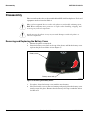
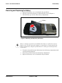
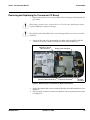
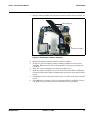
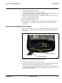
Removing and Replacing the Battery Cover
1. Ensure the phone is turned off.
2. Press the battery cover latch at the top of the phone, and lift the battery cover
up from the phone and lift it off (see Figure 3).
3. To replace, align the battery cover with the rear housing.
4. Place the battery cover on the rear housing and gently press the battery cover
until it snaps into place. Ensure that the battery door tap is tucked in below
the RF cover.
G
Many of the integrated devices used in this phone are vulnerable to damage from
ESD. Ensure adequate static protection is in place when handling, shipping, and
servicing any internal components.
G
Avoid stressing the plastic in any way to avoid damage to either the plastic or
internal components.
061492o
Figure 3. Removing the Battery Cover
Battery cover latch
Battery cover

6809510A66-O October 12, 2006 19
Level 1 and 2 Service Manual Disassembly
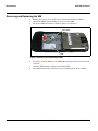
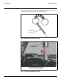
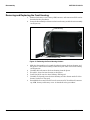
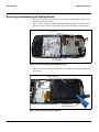
Removing and Replacing the Battery
1. Remove the battery cover as described in the procedures.
2. Lift the top end of the battery as indicated by the arrow in Figure 4.
3. Lift the battery up and out of the battery compartment.
4. To replace, insert the bottom of the battery into the battery compartment with
contacts facing downward.
5. Press the top of the battery into the battery compartment.
6. Replace the battery cover as described in the procedures.
061493o
Figure 4. Removing and Replacing the Battery
E
There is a danger of explosion if the Lithium-Ion battery is replaced incorrectly.
Replace only with the same type of battery or equivalent as recommended by the
battery manufacturer. Dispose of used batteries according to the manufacturer’s
instructions.
Battery

20 October 12, 2006 6809510A66-O
Disassembly MOTOSLVR L9/L72
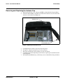
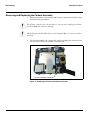
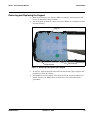
Removing and Replacing the SIM
1. Remove the battery cover and battery as described in the procedures.
2. Unlock the SIM holder by sliding it away from the SIM.
3. Lift up the SIM and remove it from the phone (see Figure 5).
4. To replace, slide the SIM into the SIM holder with the notched corner located
as shown.
5. Lock the SIM holder by sliding it toward the SIM.
6. Reassemble the battery and battery cover as described in the procedures.
061495o
Figure 5. Removing and Replacing the SIM
SIM
SIM Holder
unlock
La pagina si sta caricando...
La pagina si sta caricando...
La pagina si sta caricando...
La pagina si sta caricando...
La pagina si sta caricando...
La pagina si sta caricando...
La pagina si sta caricando...
La pagina si sta caricando...
La pagina si sta caricando...
La pagina si sta caricando...
La pagina si sta caricando...
La pagina si sta caricando...
La pagina si sta caricando...
La pagina si sta caricando...
La pagina si sta caricando...
La pagina si sta caricando...
La pagina si sta caricando...
La pagina si sta caricando...
La pagina si sta caricando...
La pagina si sta caricando...
La pagina si sta caricando...
La pagina si sta caricando...
La pagina si sta caricando...
La pagina si sta caricando...
La pagina si sta caricando...
La pagina si sta caricando...
La pagina si sta caricando...
La pagina si sta caricando...
La pagina si sta caricando...
-
 1
1
-
 2
2
-
 3
3
-
 4
4
-
 5
5
-
 6
6
-
 7
7
-
 8
8
-
 9
9
-
 10
10
-
 11
11
-
 12
12
-
 13
13
-
 14
14
-
 15
15
-
 16
16
-
 17
17
-
 18
18
-
 19
19
-
 20
20
-
 21
21
-
 22
22
-
 23
23
-
 24
24
-
 25
25
-
 26
26
-
 27
27
-
 28
28
-
 29
29
-
 30
30
-
 31
31
-
 32
32
-
 33
33
-
 34
34
-
 35
35
-
 36
36
-
 37
37
-
 38
38
-
 39
39
-
 40
40
-
 41
41
-
 42
42
-
 43
43
-
 44
44
-
 45
45
-
 46
46
-
 47
47
-
 48
48
-
 49
49


Motorola MOTOSLVR L72 Manuale utente
- Categoria
- Cellulari
- Tipo
- Manuale utente
- Questo manuale è adatto anche per
in altre lingue
- English: Motorola MOTOSLVR L72 User manual
Documenti correlati
-
Motorola PEBL U6 Manuale utente
-
-
-
Motorola V600 Manuale utente
-
Motorola E365 Manuale utente
-
-
Motorola T720 CDMA Manuale utente
-
-
-
Altri documenti
-
Makita VR001C Manuale utente
-
-
JBL REFERENCE 610 {jbl} Manuale utente
-
CommScope H350 Guida utente
-
Oakley Holeshot 3 Hand Manuale utente
-
Roland G-800 Service Notes
-
Sioux Tools TC50A Series Instructions Manual
-
Sonic Alert SS12VW Guida utente
-
ADC Network Card EMU-830 Manuale utente
-
KeySonic KSK-8001 UEL US Scheda dati