
EN
IT
FR
NL
PL
DE
SE
ES
RU
EN
IT
FR
NL
PL
DE
SE
ES
RU
FOR CAR USE ONLY/NUR FÜR AUTOMOBIL GEBRAUCH/POUR APPLICATION AUTOMOBILE UNIQUEMENT/PARA
USO EN AUTOMÓVILES/SOLO PER L’UTILIZZO IN AUTOMOBILE/ENDAST FÖR BILBRUK/ALLEEN VOOR GEBRUIK
IN DE AUTO/ТОЛЬКО ДЛЯ ИСПОЛЬЗОВАНИЯ В АВТОМОБИЛЯХ/DO UŻYCIA TYLKO W SAMOCHODZIE
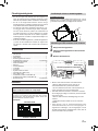
6.5-INCH NAVIGATION / DVD RECEIVER
INE-W611D
INSTALLATION MANUAL
INSTALLATIONSHANDBUCH
MANUEL D‘INSTALLATION
MANUAL DE INSTALACIÓN
MANUALE DI INSTALLAZIONE
INSTALLATIONSMANUAL
MONTAGEHANDLEIDING
РУКОВОДСТВО ПО УСТАНОВКЕ
INSTRUKCJA INSTALACJI


1
-EN
ENGLISH
Contents
WARNING ...........................................2
CAUTION .............................................2
Precautions ........................................2
Accessory List ...................................... 3
Installation ............................................ 3
Caution concerning the
installation location ............................3
Mounting the GPS Antenna
inside the vehicle ...............................3
Mounting the Microphone .................4
Installation example using the
Original Mounting Bracket .................4
Connections .......................................5
If an ACC power supply is not
available .............................................8
System Example ...............................9

2
-EN
WARNING
This symbol means important instructions. Failure to
heed them can result in serious injury or death.
DO NOT DISASSEMBLE OR ALTER.
Doing so may result in an accident, re or electric shock.
KEEP SMALL OBJECTS SUCH AS SCREWS OUT OF THE
REACH OF CHILDREN.
Swallowing them may result in serious injury. If swallowed,
consult a physician immediately.
USE THE CORRECT AMPERE RATING WHEN REPLACING
FUSES.
Failure to do so may result in re or electric shock.
DO NOT BLOCK VENTS OR RADIATOR PANELS.
Doing so may cause heat to build up inside and may result in re.
USE THIS PRODUCT FOR MOBILE 12V APPLICATIONS.
Use for other than its designed application may result in fire,
electric shock or other injury.
MAKE THE CORRECT CONNECTIONS.
Failure to make the proper connections may result in fire or
product damage.
USE ONLY IN CARS WITH A 12 VOLT NEGATIVE GROUND.
(Check with your dealer if you are not sure.) Failure to do so may
result in re, etc.
BEFORE WIRING, DISCONNECT THE CABLE FROM THE NEGA-
TIVE BATTERY TERMINAL.
Failure to do so may result in electric shock or injury due to
electrical shorts.
DO NOT ALLOW CABLES TO BECOME ENTANGLED IN SUR-
ROUNDING OBJECTS.
Arrange wiring and cables in compliance with the manual to
prevent obstructions when driving. Cables or wiring that obstruct
or hang up on places such as the steering wheel, gear lever,
brake pedals, etc. can be extremely hazardous.
DO NOT SPLICE INTO ELECTRICAL CABLES.
Never cut away cable insulation to supply power to other
equipment. Doing so will exceed the current carrying capacity of
the wire and result in re or electric shock.
DO NOT DAMAGE PIPE OR WIRING WHEN DRILLING HOLES.
When drilling holes in the chassis for installation, take precautions
so as not to contact, damage or obstruct pipes, fuel lines, tanks
or electrical wiring. Failure to take such precautions may result in
re.
DO NOT USE BOLTS OR NUTS IN THE BRAKE OR STEERING
SYSTEMS TO MAKE GROUND CONNECTIONS.
Bolts or nuts used for the brake or steering systems (or any
other safety-related system), or tanks should NEVER be used
for installations or ground connections. Using such parts could
disable control of the vehicle and cause re etc.
DO NOT INSTALL IN LOCATIONS WHICH MIGHT HINDER
VEHICLE OPERATION, SUCH AS THE STEERING WHEEL OR
GEARSHIFT.
Doing so may obstruct forward vision or hamper movement etc.
and results in serious accident.
DO NOT INSTALL THE MONITOR NEAR THE PASSENGER SEAT
AIR BAG.
If the unit is not installed correctly the air bag may not function
correctly and when triggered the air bag may cause the monitor to
spring upwards causing an accident and injuries.
CAUTION
This symbol means important instructions. Failure
to heed them can result in injury or material property
damage.
HAVE THE WIRING AND INSTALLATION DONE BY EXPERTS.
The wiring and installation of this unit requires special technical
skill and experience. To ensure safety, always contact the dealer
where you purchased this product to have the work done.
USE SPECIFIED ACCESSORY PARTS AND INSTALL THEM
SECURELY.
Be sure to use only the specied accessory parts. Use of other
than designated parts may damage this unit internally or may not
securely install the unit in place. This may cause parts to become
loose resulting in hazards or product failure.
ARRANGE THE WIRING SO IT IS NOT CRIMPED OR PINCHED BY
A SHARP METAL EDGE.
Route the cables and wiring away from moving parts (like the seat
rails) or sharp or pointed edges. This will prevent crimping and
damage to the wiring. If wiring passes through a hole in metal,
use a rubber grommet to prevent the wire’s insulation from being
cut by the metal edge of the hole.
DO NOT INSTALL IN LOCATIONS WITH HIGH MOISTURE OR
DUST.
Avoid installing the unit in locations with high incidence of moisture
or dust. Moisture or dust that penetrates into this unit may result in
product failure.

3
-EN
Precautions
• Be sure to disconnect the cable from the (–) battery post
before installing your unit. This will reduce any chance of
damage to the unit in case of a short-circuit.
• Be sure to connect the color coded leads according to
the diagram. Incorrect connections may cause the unit to
malfunction or damage to the vehicle’s electrical system.
• When making connections to the vehicle’s electrical
system, be aware of the factory installed components (e.g.
on-board computer). Do not tap into these leads to provide
power for this unit. When connecting the unit to the fuse
box, make sure the fuse for the intended circuit of the unit
has the appropriate amperage. When in doubt, consult
your Alpine dealer.
• Be sure to connect the speaker (–) leads to the speaker
(–) terminal. Never connect left and right channel speaker
cables to each other or to the vehicle body.
Accessory List
• INE-W611D....................................................................... 1
• Power cable.................................................................... 1
• GPS Antenna.................................................................. 1
• Antenna mounting plate................................................. 1
• Cable clamp for antenna........................................... 1set
• USB extension cable...................................................... 2
• PRE OUT cable.............................................................. 1
• Microphone..................................................................... 1
• Interface cable................................................................ 1
• Inner case............................................................................ 1
• Face plate............................................................................ 1
• Inner case release key....................................................... 2
• Flush Head Screw (M5 8mm)........................................... 6
• Screw (M5 8mm)............................................................... 8
• Rubber cap(only INE-W611D)............................................1
• Hex Bolt(only INE-W611D)..................................................1
• Owner’s Manual........................................................... 1set
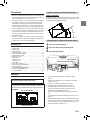
Installation
To install refer to the manual in the separately
purchased installation kit for each car type.
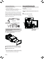
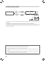
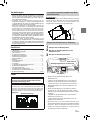
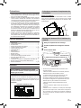
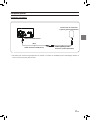
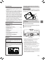
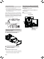
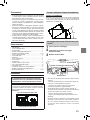
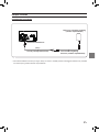
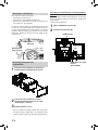
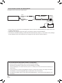
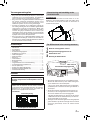
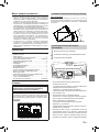
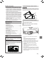
Caution
Do not block the unit’s fan, thus preventing air circulation. If
blocked, heat will accumulate inside the unit and may cause a re.
<example>
Air ventilation hole
Rear of the Unit
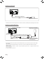
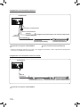
Caution concerning the installation location
Angle of installation
Install at an angle between horizontal and 30°. Note that
installing at an angle outside of this range will result in a loss
of performance and possibly damage.
0 - 30°
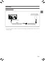
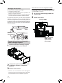
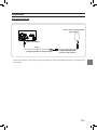
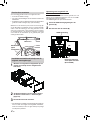
Mounting the GPS Antenna inside the vehicle
1
Clean the mounting location.
2
Put on the GPS Antenna mounting plate.
3
Mount the GPS Antenna.
• Do not mount the GPS Antenna inside the center
console.
- Mount the GPS Antenna on a at plane of the dash
board or rear tray.
- Make sure the GPS Antenna is not covered
(obstructed) by any metallic surface or object.
• If the GPS Antenna is mounted near the unit, the
reception becomes poor, and the location of your
vehicle may not be displayed correctly.
- Mount the GPS Antenna far away enough from the
unit.
- Bundle the GPS Antenna cable away from the rear of
the unit.
• Some thermal reection type or thermal absorption type
glass may interrupt high frequency waves. If reception
is poor with the antenna installed inside the car, try to
mount the antenna outside the car.
GPS Antenna
Antenna mounting plate
This unit

4
-EN
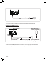
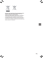
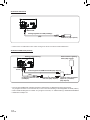
Mounting the Microphone
For safe use, make sure of the following:
• Location is stable and rm.
• Driver’s view and operations are not obstructed.
• Microphone is located where the driver’s voice can be
easily picked up (for example, on the sun visor).
When you speak into the microphone, you should not have
to change your driving posture. This may cause a distraction,
taking your attention away from safely driving your vehicle.
Carefully consider direction and distance while mounting the
microphone. Confirm that the driver’s voice can be easily
picked up at the selected location.
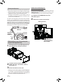
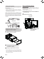
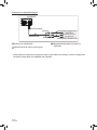
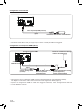
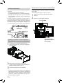
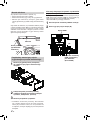
Installation example using the Original
Mounting Bracket
1
Mount the original mounting sleeve to the unit
using the supplied screws.
2
Connect all other leads of the unit according to
details described in the “Connections” (page 5).
3
Mounting the unit in a car.
• Fix the cables carefully. Do not damage them by tucking
them into movable parts, such as a seat rail, or by
locating them against sharp or pointed edges.
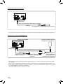
Note on using HDMI Connection Cables
When using HDMI connection cables, secure the cables
to the HDMI Terminals with the HDMI Fixation Bracket
(KCU-610HD).
*The HDMI bracket is not included.
1
Slide the HDMI Fixation Bracket into the grooves
(A).
2
Secure it with the screw (B).
Microphone
HDMI Terminal
HDMI Fixation Bracket
Sold Separtely
(KCU-610HD)
(A) (B)
Cable clamp
(Sold separately)

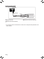
5
-EN
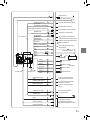
1
2
3
5
6
7
8
9
10
11 12
13
14
15
16
17
18
19
20
21
22
23
24
25
26
27
28
29
33
33
36
31
32
30
34
35
4
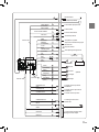
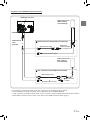
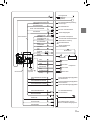
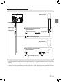
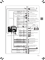
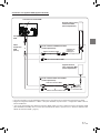
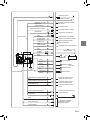
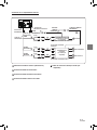
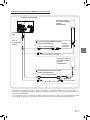
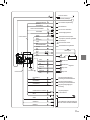
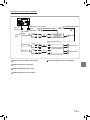
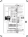
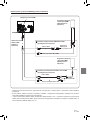
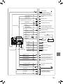
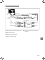
Interface cable
SPEED SENSOR
Vehicle Antenna
GPS Antenna (Included)
To the vehicle speed pulse line
To Rear camera
To Front or Side camera
To AUX output device
To amplier or equalizer
To power antenna
To the parking brake signal lead
Rear Left
Ignition key
Battery
Front Left
Speakers
Front Right
Rear Right
To remote control input lead
To input terminal of amplier when
adding an external amplier
Microphone (Included)
To steering remote control
interface box
To remote control input lead of
Rear Monitor
To remote control output lead of
Rear Monitor
To plus side of the back lamp signal
lead of the car
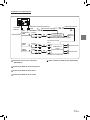
(Green/White)
(Blue/White)
REVERSE
(Orange/White)
P. ANT
(Blue)
PARKING BRAKE
(Yellow/Blue)
ACC
(Red)
BATT
(Yellow)
GND
(Black)
(Green)
(Green/Black)
(White)
(White/Black)
(Gray/Black)
(Gray)
RSE REMOTE OUT
(Gray)
RSE REMOTE IN
AUX REMOTE OUT
STEERING REMOTE
MIC IN
SUBW
FRONT OUT
REAR OUT
(Gray)
(Gray)
(Violet)
(Violet/Black)
REAR CAMERA
AUX INPUT
REMO
FRONT OR SIDE CAMERA
PRE OUT cable
Power cable

6
-EN
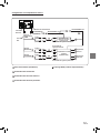
〇①〇
Radio Antenna Receptacle
〇②〇
Speed Sensor Lead (Green/White)
Improper connection of the speed pulse line may cause
important safety features of the vehicle to fail (such as the
brakes or air bags). Such failures may result in an accident
and loss of life. We strongly recommend that the installation
be performed by a trained, authorized Alpine dealer.
〇③〇
Rear Camera Input Connector (RCA)
〇④〇
Front or Side Camera Input Connector (RCA)
〇⑤〇
AUX Input Connector
Input lead for AUX video/audio signal.
〇⑥〇
Remote Turn-On Lead (Blue/White)
Connect this lead to the remote turn-on lead of your amplier
or signal processor.
〇⑦〇
Reverse Lead (Orange/White)
Connect to the plus side of the car’s reverse lights. These
lights illuminate when the transmission is shifted into reverse
(R).
With this lead properly wired, the video picture automatically
switches to the rear camera whenever the car is put into
reverse (R).
〇⑧〇
Power Antenna Lead (Blue)
Connect this lead to the +B terminal of your power antenna,
if applicable.
• This lead should be used only for controlling the vehicle’s
power antenna. Do not use this lead to turn on an amplier
or a signal processor, etc.
〇⑨〇
Parking Brake Lead (Yellow/Blue)
Connect this lead to the power supply side of parking brake
switch to transmit the parking brake status signals to the
unit.
〇⑩〇
Switched Power Lead (Ignition) (Red)
Connect this lead to an open terminal on the vehicle’s fuse
box or another unused power source that provides (+)
12V only when the ignition is turned on or in the accessory
position.
〇⑪〇
Fuse Holder (15A)
〇⑫〇
Battery Lead (Yellow)
Connect this lead to the positive (+) post of the vehicle’s
battery.
〇⑬〇
Ground Lead (Black)
Connect this lead to a good chassis ground on the vehicle.
Make sure the connection is made to bare metal and is
securely fastened using the sheet metal screw provided.
〇⑭〇
Left Rear (+) Speaker Output Lead (Green)
〇⑮〇
Left Rear (–) Speaker Output Lead (Green/
Black)
〇⑯〇
Left Front (+) Speaker Output Lead (White)
〇⑰〇
Left Front (–) Speaker Output Lead (White/
Black)
〇⑱〇
Right Front (–) Speaker Output Lead (Gray/
Black)
〇⑲〇
Right Front (+) Speaker Output Lead (Gray)
20
Right Rear (–) Speaker Output Lead (Violet/
Black)
21
Right Rear (+) Speaker Output Lead (Violet)
22
Remote Control Output Lead (Gray) (For Rear
Monitor)
Connect this lead to the remote control input lead. This lead
outputs the controlling signals from the remote control.
23
Remote Control Input Lead (Gray) (For Rear
Monitor)
Connect the external Alpine product to the remote control
output lead.
24
Remote Control Output Lead (Gray) (For Aux)
Connect this lead to the remote control input lead. This lead
outputs the controlling signals from the remote control.
25
Steering Remote Control Interface Connector
To steering remote control interface box.
For details about connections, consult your nearest Alpine
dealer.
26
MIC Input Connector
To microphone (Included)
• When using the included microphone, set Microphone
Select to “Add-on” For details, refer to “Setting the
Microphone Select” in the OWNER’S MANUAL.

7
-EN
27
Subwoofer RCA Connectors
RED is right and WHITE is left.
28
Front Output RCA Connectors
Can be used as Front Output RCA Connectors. RED is right
and WHITE is left.
29
Rear Output RCA Connectors
Can be used as Rear Output RCA Connectors. RED is right
and WHITE is left.
30
GPS Antenna Receptacle
Connect to GPS antenna (Included).
31
USB Connector
To USB ash drive, iPod/iPhone or Android smartphone.
32
HDMI Input Connector
33
Power Supply Connector
34
Interface / Wired Remote connector
35
PRE OUT Connector
36
DAB Connector

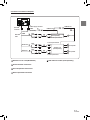
8
-EN
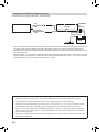
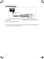
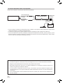
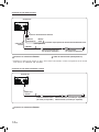
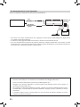
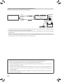
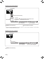
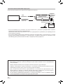
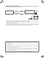
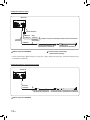
If an ACC power supply is not available
Connection Diagram of SPST Switch (sold separately)
• If your vehicle has no ACC power supply, add an SPST (single-pole, single-throw) switch (sold separately) and fuse (sold
separately).
• The diagram and the fuse amperage shown above are in the case when the unit is used individually.
• If the switched power (ignition) lead of the unit is connected directly to the positive (+) post of the vehicle’s battery, the
unit draws some current (several hundred milliamperes) even when its switch is placed in the OFF position, and the
battery may be discharged.
To prevent external noise from entering the audio system.
• Locate the unit and route the leads at least 10 cm away from the car harness.
• Keep the battery power leads as far away from other leads as possible.
• Connect the ground lead securely to a bare metal spot (remove any paint, dirt or grease if necessary) of the car
chassis.
• If you add an optional noise suppressor, connect it as far away from the unit as possible. Your Alpine dealer
carries various noise suppressors, contact them for further information.
• Your Alpine dealer knows best about noise prevention measures so consult your dealer for further information.
ACC
SPST SW (Optional)
Battery
FUSE (5A)
(Optional)
FUSE (20A)
(Optional)
(Red)
BATTERY
(Yellow)

9
-EN
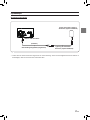
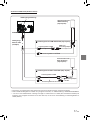
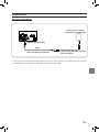
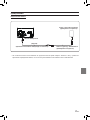
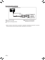
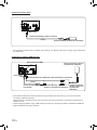
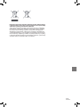
System Example
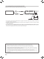
Connection of an iPhone
• Do not leave an iPhone in a vehicle for a long time. Heat and humidity may damage the iPhone, and you may not be
able to play it again.
Lower USB connector
iPhone with a Lightning
connector (sold separately)
USB extension cable (Included)
(Black)
Lightning to USB Cable
KCU-471i (sold separately)

10
-EN
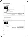
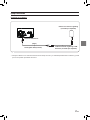
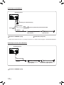
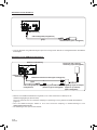
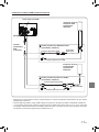
Connection of a Flash Drive
• Do not leave a ash drive in a vehicle for a long time. Heat and humidity may damage the ash drive.
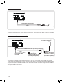
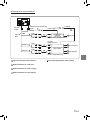
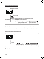
Connection of an HDMI Device (iPhone)
• When connecting an HDMI connection cable, be sure to secure it using the HDMI Fixation Bracket(KCU-610HD).
For details on how to secure it, see “Note on using HDMI Connection Cables” (page 4).
• Set the HDMI Setup to “HDMI.” For details, refer to “HDMI Setup” in the OWNER’S MANUAL.
• The HDMI bracket is not included.
USB connector
Lower USB
connector
HDMI input connector*
iPhone with a Lightning
connector (sold separately)
Lightning Digital AV Adapter
(Apple Inc., products)
(sold separately)
Lightning to USB Cable
KCU-471i (sold separately)
USB extension cable
(Included)
HDMI connection kit KCU-610HD (sold separately)
USB extension cable (Included)
USB Flash Drive (sold separately)
(Gray)
(Gray)

11
-EN
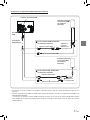
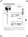
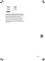
Connection of an HDMI Device (Android device)
• A connection kit or adapter kit suitable for the type of terminal on the connecting device is required.
• Set the HDMI Setup to “HDMI.” For details, refer to “HDMI Setup” in the OWNER’S MANUAL.
• * When connecting an HDMI connection cable, be sure to secure it using the HDMI Fixation Bracket (KCU-610HD/
KCU-610MH). For details on how to secure it, see “Note on using HDMI Connection Cables” (page 4).
USB connector
USB extension
cable
(Included)
HDMI input connector*
HDMI connection cable
HDMI Type-D
conversion adapter
Micro USB conversion cable
Micro USB conversion cable
HDMI connection cable
MHL conversion
adapter
HDMI connection kit KCU-610HD (sold separately)
MHL connection kit KCU-610MH (sold separately)
Android device with
HDMI connector
(sold separately)
Android device with
MHL connector
(sold separately)

12
-EN
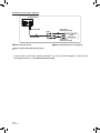
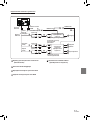
Connection of an External Device
5
I/F connector
(Yellow)
(Red)
(White)
To Video Output terminal
External Device
(sold separately)
To Audio Output terminal
5
AUX Input Connector
22
Remote Control Output Lead (Gray)
RCA Extension Cable (sold separately)
• You can change the name of an external device. For details, refer to “Setting the Auxiliary (AUX) Name” in the
OWNER’S MANUAL.
Interface cable
AUX INPUT

13
-EN
Connection of an External Amplier
6
27
28
29
6
Remote Turn-On Lead (Blue/White)
27
Subwoofer RCA Connectors
28
Front Output RCA Connectors
29
Rear Output RCA Connectors
RCA Extension Cable (sold separately)
PRE OUT
connector
Power cable
SUBW
FRONT OUT
REAR OUT
Power Supply connector
REMOTE ON
(Blue/White)
Amplier for subwoofer
(sold separately)
Amplier 4 ch
(sold separately)
To subwoofer input terminal
To front input terminal
To rear input terminal
Subwoofer
Front speaker
Rear speaker
REMO
REMOTE ON
(Blue/White)
(Red)
(Red)
(Red)
(White)
(White)
(White)
(Blue/White)
PRE OUT
cable

14
-EN
Connection of a Rearview camera
7
3
3
7
3
3
3
CAMERA Input Connector
7
Reverse Lead (Orange/White)
• Set the Camera Select to “Rear.” For details, refer to “Setting the Camera Input” in the OWNER’S MANUAL.
Connection of a Frontview or Sideview camera
7
3
3
7
3
3
I/F connector
Interface cable
Power Supply connector
Power
cable
CAMERA
Connect to the plus side of the car’s reverse lamp.
Reverse
(Orange/White)
RCA Extension Cable
(sold separately)
Rear Camera
(sold separately)
3
CAMERA Input Connector
Interface cable
CAMERA
RCA Extension Cable
(sold separately)
Frontview camera: (sold separately) or
Sideview camera: (sold separately)
I/F connector

15
-EN
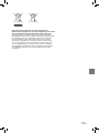
Information on Disposal of Old Electrlcal and Electronic
Equipment and Battery (applicable for countries that have adopted
spearate waste collection systems)
If you want to dispose this product, do not mix it with general household
waste. There is a separate collection system for used electronic
products in accordance with legislation that requires proper treatment,
recovery and recycling. Contact your local authority for details in
Locating a recycle facility nearest to you. Proper recycling and waste
disposal will help conserve resources whist preventing detrimental
effects on our health and the environment.


1
-DE
DEUTSCH
Inhaltsverzeichnis
WARNUNG ...................................... 2
VORSICHT ....................................... 2
VORKEHRUNGEN .......................... 2
Zubehörliste ..................................... 3
Einbau .............................................. 3
Vorsichtshinweise zum
Einbauort ........................................3
Einbau der GPS-Antenne im
Fahrzeug ........................................3
Einbau des Mikrofons ....................4
Einbaubeispiel unter Verwendung
der Original-Montagehalterung ......4
Anschlüsse .....................................5
Fahrzeuge ohne
ACC-Spannungsversorgung ..........8
Systembeispiel ...............................9

2
-DE
WARNUNG
Dieses Symbol weist auf wichtige Anweisungen
hin. Bei Nichtbeachtung besteht die Gefahr von
schweren Verletzungen oder Todesfällen.
GERÄT NICHT ÖFFNEN.
Andernfalls besteht Unfallgefahr, Feuergefahr oder die
Gefahr eines elektrischen Schlages.
KLEINE GEGENSTÄNDE WIE SCHRAUBEN VON KINDERN
FERNHALTEN.
Werden solche Gegenstände verschluckt, besteht die
Gefahr schwerwiegender Verletzungen. Suchen Sie
unverzüglich einen Arzt auf, wenn ein Kind einen solchen
Gegenstand verschluckt.
SICHERUNGEN IMMER DURCH SOLCHE MIT DER
RICHTIGEN AMPEREZAHL ERSETZEN.
Andernfalls besteht Feuergefahr oder die Gefahr eines
elektrischen Schlages.
LÜFTUNGSÖFFNUNGEN UND KÜHLKÖRPER NICHT
ABDECKEN.
Andernfalls kann es zu einem Wärmestau im Gerät
kommen, und es besteht Feuergefahr.
DAS GERÄT NUR AN EIN 12-V-BORDNETZ IN EINEM
FAHRZEUG ANSCHLIE
ẞ
EN.
Andernfalls besteht Feuergefahr, die Gefahr eines
elektrischen Schlages oder anderer Verletzungen.
AUF KORREKTE ANSCHLÜSSE ACHTEN.
Bei fehlerhaften Anschlüssen besteht Feuergefahr, und es
kann zu Schäden am Gerät kommen.
NUR IN FAHRZEUGEN MIT 12-VOLT-BORDNETZ UND MINUS
AN MASSE VERWENDEN.
(Fragen Sie im Zweifelsfall Ihren Händler.) Andernfalls
besteht Feuergefahr usw.
VOR DEM ANSCHLUSS DAS KABEL VOM MINUSPOL DER
BATTERIE ABKLEMMEN.
Andernfalls besteht die Gefahr eines elektrischen Schlages
oder Verletzungsgefahr durch einen Kurzschluss.
DAFÜR SORGEN, DASS SICH DIE KABEL NICHT IN
GEGENSTÄNDEN IN DER NÄHE VERFANGEN.
Verlegen Sie die Kabel laut Handbuch, damit sie beim
Fahren nicht hinderlich sind. Kabel, die behindern oder auf
Stellen, wie Lenkrad, Schalthebel, Bremspedal usw. herab
hängen, können sehr gefährlich sein.
ELEKTRISCHE KABEL NICHT SPLEI
ẞ
EN.
Kabel dürfen nicht abisoliert werden, um andere Geräte mit
Strom zu versorgen. Andernfalls wird die Strombelastbarkeit
des Kabels überschritten, und es besteht Feuergefahr oder
die Gefahr eines elektrischen Schlages.
BEIM BOHREN VON LÖCHERN LEITUNGEN UND KABEL
NICHT BESCHÄDIGEN.
Wenn Sie beim Einbauen Löcher in das Fahrzeugchassis
bohren, achten Sie unbedingt darauf, die Kraftstofeitungen
und andere Leitungen, den Benzintank und elektrische
Kabel nicht zu berühren, zu beschädigen oder zu blockieren.
Werden diese Vorkehrungen missachtet, so kann dies zum
Brand führen.
SCHRAUBEN UND MUTTERN DER BREMSANLAGE NICHT
ALS MASSEPUNKTE VERWENDEN.
Schrauben oder Muttern der Brems- bzw. Lenkanlage (oder
irgendein anderes sicherheitsrelevante System) oder Tanks
dürfen NIEMALS für den Einbau oder als Masseanschluss
verwendet werden. Andernfalls besteht die Gefahr, dass
Sie die Kontrolle über das Fahrzeug verlieren oder ein
Feuer ausbricht.
DAS GERÄT NICHT AN EINER STELLE EINBAUEN, AN DER
ES BEIM FAHREN HINDERLICH SEIN KÖNNTE, WEIL ES Z. B.
DAS LENKRAD ODER DEN SCHALTHEBEL BLOCKIERT.
Andernfalls ist möglicherweise keine freie Sicht nach
vorne gegeben, oder die Bewegungen des Fahrers sind so
eingeschränkt, dass Unfallgefahr besteht.
MONITOR NICHT UNMITTELBAR NEBEN DEM
BEIFAHRERAIRBAG ANBRINGEN.
Wenn das Gerät nicht korrekt eingebaut wird, funktioniert
der Airbag unter Umständen nicht ordnungsgemäß,
und bei Auslösung des Airbags kann der Monitor hoch
geschleudert werden und Verletzungen verursachen.
VORSICHT
Dieses Symbol weist auf wichtige Anweisungen
hin. Bei Nichtbeachtung besteht die Gefahr von
Verletzungen bzw. Sachschäden.
VERKABELUNG UND EINBAU VON FACHPERSONAL
AUSFÜHREN LASSEN.
Die Verkabelung und der Einbau dieses Geräts erfordern
technisches Geschick und Erfahrung. Zu Ihrer eigenen
Sicherheit sollten Sie Verkabelung und Einbau dem
Händler überlassen, bei dem Sie das Gerät erworben
haben.
NUR DAS VORGESCHRIEBENE ZUBEHÖR VERWENDEN
UND DIESES SICHER EINBAUEN.
Verwenden Sie ausschließlich das vorgeschriebene
Zubehör. Andernfalls wird das Gerät möglicherweise
beschädigt, oder es lässt sich nicht sicher einbauen. Wenn
sich Teile lösen, stellen diese eine Gefahrenquelle dar, und
es kann zu Betriebsstörungen kommen.
DIE KABEL SO VERLEGEN, DASS SIE NICHT GEKNICKT
ODER DURCH SCHARFE KANTEN GEQUETSCHT WERDEN.
Verlegen Sie die Kabel so, dass sie sich nicht in beweglichen
Teilen (bspw. Sitzschienen) verfangen oder an scharfen
Kanten oder spitzen Ecken beschädigt werden können. So
verhindern Sie eine Beschädigung der Kabel. Wenn Sie
ein Kabel durch eine Bohrung in einer Metallplatte führen,
schützen Sie die Kabelisolierung mit einer Gummitülle vor
Beschädigung durch die Metallkanten der Bohrung.
DAS GERÄT NICHT AN STELLEN EINBAUEN, AN DENEN ES
HOHER FEUCHTIGKEIT ODER STAUB AUSGESETZT IST.
Bauen Sie das Gerät so ein, dass es vor hoher Feuchtigkeit
und Staub geschützt ist. Wenn Feuchtigkeit oder Staub
in das Gerät gelangen, kann es zu Betriebsstörungen
kommen.
La pagina si sta caricando...
La pagina si sta caricando...
La pagina si sta caricando...
La pagina si sta caricando...
La pagina si sta caricando...
La pagina si sta caricando...
La pagina si sta caricando...
La pagina si sta caricando...
La pagina si sta caricando...
La pagina si sta caricando...
La pagina si sta caricando...
La pagina si sta caricando...
La pagina si sta caricando...
La pagina si sta caricando...
La pagina si sta caricando...
La pagina si sta caricando...
La pagina si sta caricando...
La pagina si sta caricando...
La pagina si sta caricando...
La pagina si sta caricando...
La pagina si sta caricando...
La pagina si sta caricando...
La pagina si sta caricando...
La pagina si sta caricando...
La pagina si sta caricando...
La pagina si sta caricando...
La pagina si sta caricando...
La pagina si sta caricando...
La pagina si sta caricando...
La pagina si sta caricando...
La pagina si sta caricando...
La pagina si sta caricando...
La pagina si sta caricando...
La pagina si sta caricando...
La pagina si sta caricando...
La pagina si sta caricando...
La pagina si sta caricando...
La pagina si sta caricando...
La pagina si sta caricando...
La pagina si sta caricando...
La pagina si sta caricando...
La pagina si sta caricando...
La pagina si sta caricando...
La pagina si sta caricando...
La pagina si sta caricando...
La pagina si sta caricando...
La pagina si sta caricando...
La pagina si sta caricando...
La pagina si sta caricando...
La pagina si sta caricando...
La pagina si sta caricando...
La pagina si sta caricando...
La pagina si sta caricando...
La pagina si sta caricando...
La pagina si sta caricando...
La pagina si sta caricando...
La pagina si sta caricando...
La pagina si sta caricando...
La pagina si sta caricando...
La pagina si sta caricando...
La pagina si sta caricando...
La pagina si sta caricando...
La pagina si sta caricando...
La pagina si sta caricando...
La pagina si sta caricando...
La pagina si sta caricando...
La pagina si sta caricando...
La pagina si sta caricando...
La pagina si sta caricando...
La pagina si sta caricando...
La pagina si sta caricando...
La pagina si sta caricando...
La pagina si sta caricando...
La pagina si sta caricando...
La pagina si sta caricando...
La pagina si sta caricando...
La pagina si sta caricando...
La pagina si sta caricando...
La pagina si sta caricando...
La pagina si sta caricando...
La pagina si sta caricando...
La pagina si sta caricando...
La pagina si sta caricando...
La pagina si sta caricando...
La pagina si sta caricando...
La pagina si sta caricando...
La pagina si sta caricando...
La pagina si sta caricando...
La pagina si sta caricando...
La pagina si sta caricando...
La pagina si sta caricando...
La pagina si sta caricando...
La pagina si sta caricando...
La pagina si sta caricando...
La pagina si sta caricando...
La pagina si sta caricando...
La pagina si sta caricando...
La pagina si sta caricando...
La pagina si sta caricando...
La pagina si sta caricando...
La pagina si sta caricando...
La pagina si sta caricando...
La pagina si sta caricando...
La pagina si sta caricando...
La pagina si sta caricando...
La pagina si sta caricando...
La pagina si sta caricando...
La pagina si sta caricando...
La pagina si sta caricando...
La pagina si sta caricando...
La pagina si sta caricando...
La pagina si sta caricando...
La pagina si sta caricando...
La pagina si sta caricando...
La pagina si sta caricando...
La pagina si sta caricando...
La pagina si sta caricando...
La pagina si sta caricando...
La pagina si sta caricando...
La pagina si sta caricando...
La pagina si sta caricando...
La pagina si sta caricando...
La pagina si sta caricando...
La pagina si sta caricando...
La pagina si sta caricando...
La pagina si sta caricando...
La pagina si sta caricando...
La pagina si sta caricando...
-
 1
1
-
 2
2
-
 3
3
-
 4
4
-
 5
5
-
 6
6
-
 7
7
-
 8
8
-
 9
9
-
 10
10
-
 11
11
-
 12
12
-
 13
13
-
 14
14
-
 15
15
-
 16
16
-
 17
17
-
 18
18
-
 19
19
-
 20
20
-
 21
21
-
 22
22
-
 23
23
-
 24
24
-
 25
25
-
 26
26
-
 27
27
-
 28
28
-
 29
29
-
 30
30
-
 31
31
-
 32
32
-
 33
33
-
 34
34
-
 35
35
-
 36
36
-
 37
37
-
 38
38
-
 39
39
-
 40
40
-
 41
41
-
 42
42
-
 43
43
-
 44
44
-
 45
45
-
 46
46
-
 47
47
-
 48
48
-
 49
49
-
 50
50
-
 51
51
-
 52
52
-
 53
53
-
 54
54
-
 55
55
-
 56
56
-
 57
57
-
 58
58
-
 59
59
-
 60
60
-
 61
61
-
 62
62
-
 63
63
-
 64
64
-
 65
65
-
 66
66
-
 67
67
-
 68
68
-
 69
69
-
 70
70
-
 71
71
-
 72
72
-
 73
73
-
 74
74
-
 75
75
-
 76
76
-
 77
77
-
 78
78
-
 79
79
-
 80
80
-
 81
81
-
 82
82
-
 83
83
-
 84
84
-
 85
85
-
 86
86
-
 87
87
-
 88
88
-
 89
89
-
 90
90
-
 91
91
-
 92
92
-
 93
93
-
 94
94
-
 95
95
-
 96
96
-
 97
97
-
 98
98
-
 99
99
-
 100
100
-
 101
101
-
 102
102
-
 103
103
-
 104
104
-
 105
105
-
 106
106
-
 107
107
-
 108
108
-
 109
109
-
 110
110
-
 111
111
-
 112
112
-
 113
113
-
 114
114
-
 115
115
-
 116
116
-
 117
117
-
 118
118
-
 119
119
-
 120
120
-
 121
121
-
 122
122
-
 123
123
-
 124
124
-
 125
125
-
 126
126
-
 127
127
-
 128
128
-
 129
129
-
 130
130
-
 131
131
-
 132
132
-
 133
133
-
 134
134
-
 135
135
-
 136
136
-
 137
137
-
 138
138
-
 139
139
-
 140
140
-
 141
141
-
 142
142
-
 143
143
-
 144
144
-
 145
145
-
 146
146
-
 147
147
-
 148
148


Alpine Electronics INE-W611DC Manuale utente
- Tipo
- Manuale utente
- Questo manuale è adatto anche per
in altre lingue
Documenti correlati
Altri documenti
-
 Alpine Serie INE-F904D Manuale utente
-
 Alpine INE-F INE-F904D Guida d'installazione
-
Alpine INE-W INE-W720D Guida d'installazione
-
Alpine Serie INE-W720D Manuale utente
-
Alpine KCX-630HD Manuale del proprietario
-
Albrecht Aktive DAB+ Scheiben-Folienantenne SMB DR54 / DR56+ / DR56C / DR57 Manuale del proprietario
-
JVC Portable Air Purifier USB Power Manuale del proprietario
-
Panasonic CAGA60N Istruzioni per l'uso
-
Garmin Antena GPS/GLONASS GA 38 Guida d'installazione
-
Clarion SRV250 Manuale utente

