
smart
Living
The smarter way to
protect your home
•
Yale Smart Home
Alarm Manual
•
SR-310 • SR-320 • SR-330 • SR-340

smart
Living
Control your home
security from your
smartphone
The smarter way to
protect your home
•

1. Location planning 4
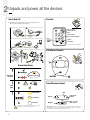
2. Un-pack all the parts 6
3. Initial set-up 8
3. Additional accessories 9
4. Mounting devices 10
5. Using the system 13
6. Default settings 15
7. Using accessories 16
8. Changing the batteries 18
9. Troubleshooting and frequently asked questions 21
10. Specifications 23
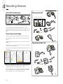
Recommended Installation Sequence
We recommend you follow the simple install
sequence, headings numbered 1-5.
Contents
Issue No: 2A
The 2 year guarantee for this Yale Smart Home
Alarm Kit is active from the date of purchase
(A copy of this guarantee is available on our
website).
Please register online within
12 months of purchase at
www.yale.co.uk/help
2
For more information on this product and Yale Smart Living Range visit www.yale.
co.uk/smart-living
Consumer Support: www.yale.co.uk/help
smart
Living

4
Y ale
ale
Y
1
2
3
6
5
4
7
8
9
0
ale
Y
ale
Y
1
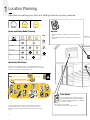
Plan device locations and part arm settings before mounting devices.
Home and Away Mode Planning
Operating 30m Range
Key Pad
• Key Pad should be accessible from a protected entry/exit
point
• Ensure that the Key Pad is not visible from the outside of the
premises.
Panic Button
The Panic Button provides extra protection for you
and your family. When needed the Panic Button
can activate your alarm immediately - even when
the system is disarmed.
• Keep out of reach of children
• Keep hidden from view while easily accessible.
Location Planning
(25)
(GB) Sensor setting - (IT) Configurazione sensore -
(DE) Sensoreinstellungen - (NO) Oppsett av sensor - (SE) Sensorinställningar -
(DK) Sensor indstilling.
Burglar
Home Omit
Entry
Bypass
Chime
Intrusione
Escluso attivazione parziale
Entrata
Bypass
Notifica acustica
Alarmanlage
Zuhause Modus
Eingang
Unterdrückung
Klingel
Innbrudd
Aktiv alarm hjemme
Inngangssone
Forbikoblet
Dørklokke
Inbrott
Från vid hemlarmat
Entré sektion
Frånkoppla
Ding dong
Indbrud
GB
IT
DE
NO
SE
DK
GB
IT
DE
NO
SE
DK
GB
IT
DE
NO
SE
DK
GB
IT
DE
NO
SE
DK
GB
IT
DE
NO
SE
DK
Fra mens hjemme
Indgangszone
Frakoblet
Dørklokke
Information and illustrations are subject to change within this document. Yale
reserves the right to alter the specification and product design at anytime
without notice. Yale® is a registered trademark. © 2017 ASSA ABLOY. All rights
reserved.
(GB) Installation - (IT) Installazione - (DE) Installation - (NO) Installasjon - (SE) Installation -
(DK) Installation.
Remove battery strips
(1
Test your planned location of components (2
Test location for radio signal strength (4
Press button to test connection
(3
(11)
(1 (IT) Rimuovi la linguetta della batteria - (DE) Entfernen der Batteriefolie - (NO) Fjern plastbeskyttelsen på batteriet
(SE) Ta bort batterifliken - (DK) Fjern batteri-strimmel
(2 (IT) Verifica la posizione scelta per i dispositivi - (DE) Testen Sie den geplanten Standort -
(NO) Test plasseringen av komponenten - (SE) Testa tilltänkta placeringen av sensorerna -
(DK) Test komponent placering
(3 (IT) Premere il pulsante per verificare la connessione - (DE) Drücken Sie den Knopf um die Verbindung zu testen
(NO) Trykk på knappen for å teste forbindelse - (SE) Tryck på knappen för att testa kopplingen -
(DK) Tryk knap for test af forbindelse.
(4 (IT) Verifica la connessione nella posizione prescelta - (DE) Testen Sie den Ort für die Stärke des Signals -
(NO) Test plassering i forhold til stabilitet av de trådløse signalene - (SE) Testa radiosignalens styrka -
(DK) Test placering for god trådløs forbindelse
8 9
5
6
1
a
a
d
b
b
c
2
3
4
5 6
(12)
(GB) Installation - (IT) Installazione - (DE) Installation - (NO) Installasjon - (SE) Installation -
(DK) Installation.
Ø 3.5mm
Ø 5mm
7
Disarmed
Part Armed
Armed
All devices must be within 30 metres of the Smart Hub and must not be
mounted on or near large metal objects. Avoid obvious sources of electrical
interference such as fridges and microwave ovens.
Burglar
Home Omit
Entry
Home Access
Disarmed Part-Armed Armed
Key
Burglar
Home Omit
Entry
Home Access
Disarmed Part-Armed Armed
Sensor
Ignored
Burglar
Home Omit
Entry
Home Access
Disarmed Part-Armed Armed
Instant Siren
Burglar
Home Omit
Entry
Home Access
Disarmed Part-Armed Armed
Triggers
Countdown

5
Y ale
ale
Y
1
2
3
6
5
4
7
8
9
0
ale
Y
ale
Y
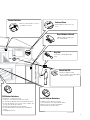
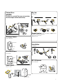
PIR Motion Detectors
• Mount 1.8m - 2.1m above floor level
• Location in a corner will ensure wider room coverage
• Do not mount the PIR where its field of view will be obstructed
• Do not point directly at sources of heat e.g. fires or boilers, and
do not position directly above radiators
• Avoid mounting the PIR directly facing a window
• Do not point the PIR at a door protected by a Door/Window
Contact
• Pet PIR Motion Detectors
Smoke Detector
External Siren
Mount as high as possible, out of easy
reach.
Door/Window Contact
• Mount as high as possible on the
door or window frame.
Key Fob
• Use inside or outside within a 30m
range
Smart Hub 2.0
• Ensure it is hidden from view.
• Access to a mains socket and broadband
internet router is required.
Introduction
(02)
Thank you for choosing the Yale Smart Home Alarm kit. This simple to install system has
been designed with the user in mind.
All the components are self contained and no connections are needed between the
units. There is no need to damage the home decor, lift carpets or run cables.
You can install up to 20 devices (Max. 6 PIR Cameras) in this system. As well as extra
door/window contacts, PIRs and smoke detectors, you can add keyfob remote controls
and keypads for added control convenience.
There is no need to wire into the mains supply or seek the services of a qualied
electrician. The Smart HUB is powered by an adaptor and all other components are
powered by battery (all batteries included). Batteries will operate for 2 years or more
before they need changing. Regular testing and battery changes (when notied by the
system) will ensure reliability and peace of mind.
The security detectors and external siren are ‘tamper’ protected. Any unauthorised
tampering with these items when the system is armed will result in an alarm.
Display extreme caution when using ladders or steps, please follow manufacturer’s
instructions. Be careful when using hand and power tools and follow the manufacturer’s
guidelines when using them. Take care that the correct tools are used. Wear goggles or
protective clothing where required. The external Siren is extremely loud, please ensure
you replace the cover and retreat to a safe distance before testing.
The dialling facilities must only be used with persons who have consented to being
contacted by the system. The system is not to be used to make 999 emergency calls
directly. Yale do not hold responsibility for any actions taken by emergency services for
incorrect use of the dialling facility.
Special Notes on Compatibility: This alarm system is NOT compatible with HSA6000
series and HSA3000 series accessories. Please note the prex “EF- & SR-” on the front of
the part number to indicate compatibility.
(03)
Learn
Power
LAN
Battery
<On Off>
1
2
3
4
5
6
7
Learn
Power
LAN
Battery
<On Off>
(p. 04-06)
(p. 07)
(p. 08)
(p. 09-10)
(p. 22-24)(p. 11)
(p. 11)
(p. 12-21)
(GB) Step by step index -
Accessories vary depending on kit
Pet PIR Motion Detectors
• Suitable for homes with pets up to 25kg
• For rooms where pets are active and may climb on
furniture, protect the area with a door/window
contact instead to prevent false alarms.
30M
30M
30M
30M
30M
Mount on a ceiling in main access areas
e.g. hallways, top of stairs.

6
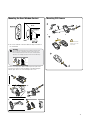
Unpack and power all the devices
2
Smart Hub 2.0
1. Plug in the power adaptor and connect the Smart Hub to your
internet router using the cable provided.
Key Pad
PIR Motion Detector
Door/Window Contact
ale
Y
1
2
3
6
5
4
7
8
9
0
Panic button A
Panic button B
Disarm
Home
Arm
LED
Learn button=
Press 8 and 9 together
/
Away
ale
Y
Status
LED
Learn/Test button Cover
screw
1
2
4
(09)
(GB) Setting up - (IT) ITSetting up - (DE) DESetting up - (NO) NOSetting up - (SE) SESetting up -
(DK) Opsætning.
3
a
b
4
Router
NOT INCLUDED
Learn
Power
LAN
Batt
ery
<On O>
Battery
<On O>
<On O>
Learn
P
ower
LAN
Battery
<On O>
OR
a
b
c
Ø5mm
Learn
Pow
er
L
AN
Bat
tery
<On O
>
a
b
(10)
(GB) Reset - (IT) Reset - (DE) Reset - (NO) Tilbakestill - (SE) Återställning - (DK) Nulstil .
Learn
Power
LAN
Battery
<On Off>
Battery
<On Off>
<On Off>
Learn
Power
LAN
Battery
<On Off>
<On Off>
HOME SERVER
GB - Network
IT - Rete
DE - Netzwerk
NO - Nettverk
SE - Nätverk
DK - Netværk
GB - Fault Status
IT - Guasto Stato
DE - Fehlerstatus
NO - Feil Status
SE - Felindikering
DK - Fejlstatus
GB - PANEL MODE
IT - Modalitá Pannello
DE - Panel-Modus
NO - Panel Mode
SE - Larmstatus
DK - Panel tilstand
4
(GB) Setting up - (IT) Configurazione - (DE) Einstellung -
(NO) Tilkobling og montering av alarmsentralen - (SE) Driftsättning -
(DK) Opsætning.
(GB) Installation - (IT) Installazione - (DE) Installation - (NO) Installasjon - (SE) Installation -
(DK) Installation.
Remove battery strips
(1
Test your planned location of components (2
Test location for radio signal strength (4
Press button to test connection
(3
(11)
(1 (IT) Rimuovi la linguetta della batteria - (DE) Entfernen der Batteriefolie - (NO) Fjern plastbeskyttelsen på batteriet
(SE) Ta bort batterifliken - (DK) Fjern batteri-strimmel
(2 (IT) Verifica la posizione scelta per i dispositivi - (DE) Testen Sie den geplanten Standort -
(NO) Test plasseringen av komponenten - (SE) Testa tilltänkta placeringen av sensorerna -
(DK) Test komponent placering
(3 (IT) Premere il pulsante per verificare la connessione - (DE) Drücken Sie den Knopf um die Verbindung zu testen
(NO) Trykk på knappen for å teste forbindelse - (SE) Tryck på knappen för att testa kopplingen -
(DK) Tryk knap for test af forbindelse.
(4 (IT) Verifica la connessione nella posizione prescelta - (DE) Testen Sie den Ort für die Stärke des Signals -
(NO) Test plassering i forhold til stabilitet av de trådløse signalene - (SE) Testa radiosignalens styrka -
(DK) Test placering for god trådløs forbindelse
8 9
5
6
Alarm Hub Status
Connected
to server
Fault
Light
Fully Armed
Part Armed
Disarmed
Unit must be turned on otherwise orange light
will appear on Smart Hub.
See page 16 for Key pad installation.
ale
Y
Learn/Test
button
LED
Gap no more
than 10mm
Magnet
Sensor
Please Note: The door sensor will not work correctly if the magnet is parallel to the
curved part of the sensor or similar statement. MUST be mounted as in the diagram,
either vertically or horizontally. Also FLUSH with each other.
Alarm hub status (and troubleshooting page 225) – the red led
will extinguish on the next alarm arm/disarm cycle.

7
External Siren
WARNING
The Siren is very loud! Take care not to activate
the Siren tamper switch unnecessarily.
Remove battery tab.
Insert batteries
Plug in to socket.
Key Fob
Insert battery
Smoke Detector Enter into self-calibration Note: mode for
10 minutes. It will resume normal once
batteries have been inserted.
Replace the cover.
Panic Button
Insert battery
Learn/Test button
Camera
Flash light
Learn: Hold for 10 seconds
Test: Hold for 1 second
On/Off, Test &
Learn button
Learn: Hold for 10 seconds
Power On/Off: Press & release
Test: Press & release
Power Switch
ale
Y
Status
LED
Learn/Test button Cover
screw
(21)
7
1
3
4 5
2
6
a
a
a
b
b
b
c
d
(GB) Installation - (IT) Installazione - (DE) Installation - (NO) Installasjon - (SE) Installation -
(DK) Installation.
Ø 5mm
(21)
7
1
3
4 5
2
6
a
a
a
b
b
b
c
d
(GB) Installation - (IT) Installazione - (DE) Installation - (NO) Installasjon - (SE) Installation -
(DK) Installation.
Ø 5mm
(GB) Installation - (IT) Installazione - (DE) Installation - (NO) Installasjon - (SE) Installation -
(DK) Installation.
Remove battery strips
(1
Test your planned location of components (2
Test location for radio signal strength (4
Press button to test connection
(3
(11)
(1 (IT) Rimuovi la linguetta della batteria - (DE) Entfernen der Batteriefolie - (NO) Fjern plastbeskyttelsen på batteriet
(SE) Ta bort batterifliken - (DK) Fjern batteri-strimmel
(2 (IT) Verifica la posizione scelta per i dispositivi - (DE) Testen Sie den geplanten Standort -
(NO) Test plasseringen av komponenten - (SE) Testa tilltänkta placeringen av sensorerna -
(DK) Test komponent placering
(3 (IT) Premere il pulsante per verificare la connessione - (DE) Drücken Sie den Knopf um die Verbindung zu testen
(NO) Trykk på knappen for å teste forbindelse - (SE) Tryck på knappen för att testa kopplingen -
(DK) Tryk knap for test af forbindelse.
(4 (IT) Verifica la connessione nella posizione prescelta - (DE) Testen Sie den Ort für die Stärke des Signals -
(NO) Test plassering i forhold til stabilitet av de trådløse signalene - (SE) Testa radiosignalens styrka -
(DK) Test placering for god trådløs forbindelse
8 9
5
6
Camera
Flash light
Learn/Test button
Learn: Hold for 10 seconds
Test: Hold for 1 second
SR-SD
SR-PB
(GB) Changing batteries - (IT) Sostituzione batterie - (DE) Batteriewechsel - (NO) Batteribytte -
(SE) Batteribyte - (DK) Batteriskift.
(23)
3 x 1.5v AA
CR 2032
SR-KF
CR 2032
3 x 1.5v AA
SR-PVC
(Lithium)
1.
2.
SR-SD
SR-PB
(GB) Changing batteries - (IT) Sostituzione batterie - (DE) Batteriewechsel - (NO) Batteribytte -
(SE) Batteribyte - (DK) Batteriskift.
(23)
3 x 1.5v AA
CR 2032
SR-KF
CR 2032
3 x 1.5v AA
SR-PVC
(Lithium)
1. 2. 3.
SR-SD
SR-PB
(GB) Changing batteries - (IT) Sostituzione batterie - (DE) Batteriewechsel - (NO) Batteribytte -
(SE) Batteribyte - (DK) Batteriskift.
(23)
3 x 1.5v AA
CR 2032
SR-KF
CR 2032
3 x 1.5v AA
SR-PVC
(Lithium)
1. 3.
PIR Image Camera
ON / OFF
On/Off, Test &
Learn button
Learn: Hold for 10 seconds
Power On/Off: Press & release
Test: Press & release
(GB) Installation - (IT) Installazione - (DE) Installation - (NO) Installasjon - (SE) Installation -
(DK) Installation.
Remove battery strips
(1
Test your planned location of components (2
Test location for radio signal strength (4
Press button to test connection
(3
(11)
(1 (IT) Rimuovi la linguetta della batteria - (DE) Entfernen der Batteriefolie - (NO) Fjern plastbeskyttelsen på batteriet
(SE) Ta bort batterifliken - (DK) Fjern batteri-strimmel
(2 (IT) Verifica la posizione scelta per i dispositivi - (DE) Testen Sie den geplanten Standort -
(NO) Test plasseringen av komponenten - (SE) Testa tilltänkta placeringen av sensorerna -
(DK) Test komponent placering
(3 (IT) Premere il pulsante per verificare la connessione - (DE) Drücken Sie den Knopf um die Verbindung zu testen
(NO) Trykk på knappen for å teste forbindelse - (SE) Tryck på knappen för att testa kopplingen -
(DK) Tryk knap for test af forbindelse.
(4 (IT) Verifica la connessione nella posizione prescelta - (DE) Testen Sie den Ort für die Stärke des Signals -
(NO) Test plassering i forhold til stabilitet av de trådløse signalene - (SE) Testa radiosignalens styrka -
(DK) Test placering for god trådløs forbindelse
8 9
5
6
PET PIR Detector
Remove battery tab.
2. Insert batteries
PIR Video Camera

8
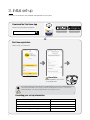
3. Initial set-up
Please ensure all devices are powered and operational at this point.
Download the Yale Home App
Internet Connection: Required on Smartphone
First time registration
Follow the in App set-up instructions.
E-mail used to set up system:
Smart Security Hub 2.0 serial number
Phone number used for notifications:
Keypad PIN Code for Disarm/Arm (default 1234):
Keypad code for keypad setting (default 0000):
Recording your set-up information
iOS 9 +
Android 4.2 +
(08)
(GB) App download - (IT) Scarica l'App -
(DE) App Download - (NO) Nedlasting av App - (SE) Installera appen -
(DK) Installer APP.
Yale Smart Living Home
3
IOS 9.0 +
Android 4.2 +
Serial No.
(08)
(GB) App download - (IT) Scarica l'App -
(DE) App Download - (NO) Nedlasting av App - (SE) Installera appen -
(DK) Installer APP.
Yale Smart Living Home
3
IOS 9.0 +
Android 4.2 +
Serial No.
If you encounter errors, it is due to the Smart Hub not communicating with our server. Please see “Warning LED” (page 22).
Please register the hub within one hour of power up, otherwise app ‘authentication error’ appears – re-boot the hub
(including switching off / on the back-up battery) and start the process again if necessary.
Please Note:
Panel Serial Number can be found on
the Smart Hub sticker.
Serial No.

9
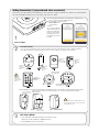
Adding Accessories (if you purchased extra accessories)
All accessories in the kit are linked to the Smart Hub. You can also add devices using the “Add new device” button in the Smart Living Home
app. Start Learning Mode and then press the learn button on the device to be added.
Exit Learn Mode:
1. Press and hold the Smart Hub Learn button for at least 6 seconds.
After the 6 seconds you will hear a slightly longer beep.
2. Your Smart Hub is now out of Learn mode.
3
1. Press and hold the learn button on your Smart Hub. you will hear a beep,
after 6 seconds you will hear a slightly longer beep.
2. Your Smart Hub is now in learn mode.
Please Note: Back
up battey must be
turned on.
3. You can also add devices
using the “Add new device”
button in the Smart Living
Home app. Start Learning
Mode and then press the
learn button on the device to
be added.
1
Enter Learn Mode
Learn/ Test
button
Press & hold
for 3 seconds
Learn/Test
button
One single
press.
For the following accessories, please hold the Learn button for 10 seconds, before releasing to enter Learn mode.
Learn/Test
button
One single
press.
Learn/Test button
One single press.
Hold for 10 seconds
Hold for 10 seconds
Hold for 10 seconds
Learn/Test button
One single press.
Learn/Test
button
One single
press.
Learn/Test
button
Press 8 and 9
together
Learn/Test button
Learn/Test button
Learn/Test button
LED
One by one, press the learn button on the accessory according to below. The Smart Hub will beep (single or multiple dependent on
device) when a new device is registered, and after a couple of seconds you will see it in your Device List on your App.
2
If the accessory doesn’t learn in, remove the batteries for 5 seconds, then replace and try relearning
within 3 minutes.
EF-PETPIR
SR-PC SR-PVC SR-PS
Learn in Accessories
Ensure you
initialise your
keypad before
you learn it. (See
page 17)
SR-PVC must be learned in with the tamper screw
removed so that the tamper is open. Sensor will not
learn with tamper closed.

10
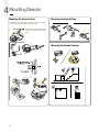
Mounting Devices
4
Smart Hub 2.0 Mounting
The Smart Hub can be free standing, either vertically or horizontally on a
flat surface with access to mains socket and broadband internet router.
It is also suitable for wall mounting. Using the two holes on the
mounting back plate, mark the position of the holes. Drill two holes and
fix with the screws and plugs provided. Hook the Smart Hub onto the
plate.
Check Accessories Range
1.) Place each device in the location where you wish to mount them.
Before mounting each device. Please check the system with a simple
range test.
Login to your Yale Home App. Select “Tests”, “Device List” then select
“Walk Test”.
Hold the devices in the desired location and press the Test/Learn button
on the accessories. (see page 9)
If the sensor signal reached the Smart Hub, it will show in the device list
on your app.
When you are happy that all your devices can communicate with the
Smart Hub, please proceed to mounting the accessories.
Before you mount a device use the device settings in the Smart Living
Home app to bypass the device and disable the tamper alert. After the
device is fully in place don’t forget to disable the bypass.
Mounting the PIR
Mounting the Key Pad
1
a
d
b
c
~1.8m
2.1m
2
a
a
b
b
3
4
5
6
(16)
(GB) Installation - (IT) Installazione - (DE) Installation - (NO) Installasjon - (SE) Installation -
(DK) Installation.
Ø 5mm
Ø 3.5mm
7
2.
3.
4. 5.
Corner Mounting
Flat Mounting
1
a
a
d
b
b
c
2
3
4
5
6
(12)
(GB) Installation - (IT) Installazione - (DE) Installation - (NO) Installasjon - (SE) Installation -
(DK) Installation.
Ø 3.5mm
Ø 5mm
7
2.
3.
1.
4.
5.
1
a
d
b
c
~1.8m
2.1m
2
a
a
b
b
3
4
5 6
(16)
(GB) Installation - (IT) Installazione - (DE) Installation - (NO) Installasjon - (SE) Installation -
(DK) Installation.
Ø 5mm
Ø 3.5mm
7
1.
1
2
4
(09)
(GB) Setting up - (IT) Configurazione - (DE) Einstellung -
(NO) Tilkobling og montering av alarmsentralen - (SE) Driftsättning -
(DK) Opsætning.
3
a
b
4
Router
NOT INCLUDED
Learn
Power
LAN
Battery
<On Off>
Battery
<On Off>
<On Off>
Learn
Power
LAN
Battery
<On Off>
OR
a
b
c
Ø5mm
Learn
Power
LAN
Battery
<On Off>
a
b
ø6mm

11
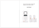
Mounting the Door/Window Contact
1. The sensor should be on the frame while the magnet should be on
the door/window.
Clean the mounting surface with a suitable degreaser agent. Please
note that some surfaces may be unsuitable for mounting using the
adhesive pads. Please use screw mounting in these cases.
Mounting PIR Camera
Testing
The gap between the magnet and sensor should be no more than 10mm
when closed. Test to see whether the magnet is in range of the sensor:
before mounting hold the magnet and sensor in place and then pull them
apart. If the sensor LED lights up it implies the two items are within range.
1
3
5
6 7
2
4
a
a
b
b
max 10mm
or
(14)
(GB) Installation - (IT) Installazione - (DE) Installation - (NO) Installasjon - (SE) Installation -
(DK) Installation.
Ø 3.5mm
7
1
3
5
6 7
2
4
a
a
b
b
max 10mm
or
(14)
(GB) Installation - (IT) Installazione - (DE) Installation - (NO) Installasjon - (SE) Installation -
(DK) Installation.
Ø 3.5mm
7
2.
1
3
5
6 7
2
4
a
a
b
b
max 10mm
or
(14)
(GB) Installation - (IT) Installazione - (DE) Installation - (NO) Installasjon - (SE) Installation -
(DK) Installation.
Ø 3.5mm
7
4.
1
3
5
6 7
2
4
a
a
b
b
max 10mm
or
(14)
(GB) Installation - (IT) Installazione - (DE) Installation - (NO) Installasjon - (SE) Installation -
(DK) Installation.
Ø 3.5mm
7
5.
1
3
5
6 7
2
4
a
a
b
b
max 10mm
or
(14)
(GB) Installation - (IT) Installazione - (DE) Installation - (NO) Installasjon - (SE) Installation -
(DK) Installation.
Ø 3.5mm
7
3.
1
3
5
6 7
2
4
a
a
b
b
max 10mm
or
(14)
(GB) Installation - (IT) Installazione - (DE) Installation - (NO) Installasjon - (SE) Installation -
(DK) Installation.
Ø 3.5mm
7
or
a
d
b
c
Ø 5 mm
4
5 6
a
b
a
d
b
c
Ø 5 mm
4
5
6
a
b
a
d
b
c
Ø 5 mm
4
5
6
a
b
Please be careful when
removing case as cable
is very delicate.
6.
1
3
5
6 7
2
4
a
a
b
b
max 10mm
or
(14)
(GB) Installation - (IT) Installazione - (DE) Installation - (NO) Installasjon - (SE) Installation -
(DK) Installation.
Ø 3.5mm
7
ø6mm

12
Mounting Devices
4
1
1
1
2
3
(15)
(GB) Installation - (IT) Installazione - (DE) Installation - (NO) Installasjon - (SE) Installation -
(DK) Installation.
Pair / Test button
Pair / Test button
(IT) Associazione/test - (DE) Verbinden/Testen -
(NO) Tilkobling/Test - (SE) Para/Testa - (DK) Tilslut/test
(IT) Associazione/test - (DE) Verbinden/Testen -
(NO) Tilkobling/Test - (SE) Para/Testa - (DK) Tilslut/test
Ø 5mm
7
1.
2.
3.
1
1
1
2
3
(15)
(GB) Installation - (IT) Installazione - (DE) Installation - (NO) Installasjon - (SE) Installation -
(DK) Installation.
Pair / Test button
Pair / Test button
(IT) Associazione/test - (DE) Verbinden/Testen -
(NO) Tilkobling/Test - (SE) Para/Testa - (DK) Tilslut/test
(IT) Associazione/test - (DE) Verbinden/Testen -
(NO) Tilkobling/Test - (SE) Para/Testa - (DK) Tilslut/test
Ø 5mm
7
1
1
1
2
3
(15)
(GB) Installation - (IT) Installazione - (DE) Installation - (NO) Installasjon - (SE) Installation -
(DK) Installation.
Pair / Test button
Pair / Test button
(IT) Associazione/test - (DE) Verbinden/Testen -
(NO) Tilkobling/Test - (SE) Para/Testa - (DK) Tilslut/test
(IT) Associazione/test - (DE) Verbinden/Testen -
(NO) Tilkobling/Test - (SE) Para/Testa - (DK) Tilslut/test
Ø 5mm
7
Mounting the External Siren
The tamper spring is fully compressed when the siren is mounted. If
there is a gap, pack with a suitable spacing material.
Mounting the Panic Button
Mounting the Smoke Detector
(21)
7
1
3
4 5
2
6
a
a
a
b
b
b
c
d
(GB) Installation - (IT) Installazione - (DE) Installation - (NO) Installasjon - (SE) Installation -
(DK) Installation.
Ø 5mm
1.
(21)
7
1
3
4 5
2
6
a
a
a
b
b
b
c
d
(GB) Installation - (IT) Installazione - (DE) Installation - (NO) Installasjon - (SE) Installation -
(DK) Installation.
Ø 5mm
2.
(21)
7
1
3
4 5
2
6
a
a
a
b
b
b
c
d
(GB) Installation - (IT) Installazione - (DE) Installation - (NO) Installasjon - (SE) Installation -
(DK) Installation.
Ø 5mm
3.
4.
Powering up the siren will automatically
disable the siren tamper for three hour
period.
-
 1
1
-
 2
2
-
 3
3
-
 4
4
-
 5
5
-
 6
6
-
 7
7
-
 8
8
-
 9
9
-
 10
10
-
 11
11
-
 12
12


in altre lingue
- English: Yale Smart Home Alarms User manual
Documenti correlati
Altri documenti
-
Crow RUNNER 8/64 Guida d'installazione
-
 Tiiwee X3 Home Alarm Kit XL Manuale utente
-
ADEMCO Security System VISTA-15CN Installation And Setup Manual
-
-
Eminent e-Alarm specificazione
-
Risco Agility Manuale utente
-
 Tiiwee X1 Manuale utente
-
Pyronix Matrix 832 Guida d'installazione
-
König SEC-ALARM100 specificazione
-
Marmitek HOMEGUARD MS8000 Manuale utente

