
1
USER’S GUIDE
CUSTOMER SERVICE CONTACTS
Suunto Oy Phone +358 9 875870
Fax +358 9 87587301
Suunto USA Phone 1 (800) 543-9124
Canada Phone 1 (800) 776-7770
European Call Center Phone +358 2 284 11 60
Suunto Website
www.suunto.com
EN

2
TABLE OF CONTENTS
CHAPTER 1 INTRODUCTION .......................................................... 6
1.1 GENERAL INFORMATION .......................................................................................... 6
1.2 MAIN FUNCTIONS (MODES) ...................................................................................... 6
1.2.1 Backlight Features ......................................................................................... 7
1.2.2 Water Resistance .......................................................................................... 7
1.3 BUTTON FUNCTIONS ................................................................................................ 7
1.3.1 The [Mode] Button ......................................................................................... 7
1.3.2 The [+] Button ................................................................................................ 8
1.3.3 The [-] Button ................................................................................................. 8
1.3.4 The [Select] Button ........................................................................................ 8
1.4 LCD DISPLAY .............................................................................................................. 8
1.5 MEASUREMENTS AND UNITS ................................................................................. 10
1.5.1 Selecting the Units of Measurement ............................................................ 10
1.6 PRESSURE SENSOR CALIBRATION ........................................................................ 11
1.7 CARE AND MAINTENANCE ....................................................................................... 11
1.7.1 Battery Replacement ................................................................................... 12
CHAPTER 2 TIME MODE ............................................................... 13
2.1 HOW TO SET THE TIME .......................................................................................... 13
2.2 DAILY ALARM SUB MODE ........................................................................................ 15
2.2.1 How to Set the Daily Alarms ........................................................................ 15
2.3 STOPWATCH SUB MODE ........................................................................................ 16
2.3.1 How to Use the Stopwatch .......................................................................... 16
2.4 COUNTDOWN TIMER SUB MODE........................................................................... 17
2.4.1 How to Set the Countdown Timer ................................................................ 18

3
2.4.2 How to Start the Countdown Timer .............................................................. 18
2.5 DUAL TIME SUB MODE (ALTIMAX , S-LANDER) ..................................................... 19
2.5.1 Setting the Dual Time Function ................................................................... 19
CHAPTER 3 ALTIMETER MODE .................................................... 20
3.1 SETTING THE ALTIMETER ....................................................................................... 21
3.2 ALTITUDE DIFFERENCE MEASUREMENT SUB MODE .......................................... 23
3.2.1 How to Start the Altitude Difference Measurement ...................................... 23
3.3 24-HOUR MEMORY SUB MODE ............................................................................... 24
3.4 LOGBOOK SUB MODE ............................................................................................. 24
3.4.1 How to Start and Stop a Logbook ................................................................ 26
3.4.2 Fast Cumulative Button ............................................................................... 26
3.5 LOGBOOK HISTORY SUB MODE ............................................................................ 27
3.5.1 Clearing the Logbook History ...................................................................... 28
CHAPTER 4 BAROMETER MODE .................................................. 28
4.1 PRESSURE DIFFERENCE MEASUREMENT SUB MODE ........................................ 29
4.1.1 How to Start the Pressure Difference Measurement .................................... 30
4.2 4-DAY MEMORY SUB MODE .................................................................................... 30
4.3 SEA LEVEL PRESSURE SUB MODE ........................................................................ 31
4.3.1 Setting the Sea Level Pressure ................................................................... 31
4.4 BAROMETRIC TREND INDICATOR .......................................................................... 32
CHAPTER 5 COMPASS MODE (VECTOR AND X-LANDER) ............ 32
5.1 BEARING TRACKING SUB MODE ............................................................................ 34
5.2 DECLINATION ADJUSTMENT SUB MODE ............................................................... 34
5.2.1 Setting the Local Declination ....................................................................... 35
5.3 CALIBRATING THE COMPASS ................................................................................. 35

4
CHAPTER 6 FREQUENTLY ASKED QUESTIONS ........................... 36
6.1 GENERAL .................................................................................................................. 36
6.1.1 Is the Wristop Computer waterproof? .......................................................... 36
6.1.2 How long will the battery last? ..................................................................... 36
6.1.3 What do the segments on the circumference mean? .................................. 37
6.1.4 Why do the segments on the circumference go to the left
(counterclockwise)? .................................................................................... 37
6.1.5 Why are there two symbols above the mode indicator bar and what do
they mean? ................................................................................................. 37
6.2 TIME .......................................................................................................................... 38
6.2.1 Why do the segments on the circumference increase and decrease when
I am in the Time mode? .............................................................................. 38
6.2.2 What is the longest time I can set in the timer? .......................................... 38
6.3 ALTIMETER ............................................................................................................... 38
6.3.1 How do you clear the logbook? ................................................................... 38
6.3.2 How does the logbook self-erase? .............................................................. 38
6.3.3 How many logbooks can you record? ......................................................... 38
6.3.4 What is the duration readout? ..................................................................... 39
6.3.5 What is the maximum capacity of total vertical ascent or descent feet/
meters in the logbook history? .................................................................... 39
6.3.6 If hiking from a level of 5,000 ft down hill to 3,000 ft and then back up to
8,000 feet, how is the Vector going to read this or average it out? ............. 39
6.3.7 Why does the vertical ascent/descent measurement show different
readings even though I am inside and staying in the same room? ............. 40
6.4 BAROMETER ............................................................................................................ 40
6.4.1 What is the little box on the top left of the display? ..................................... 40

5
6.4.2 Does the Wristop Computer show future trends in weather conditions? ..... 41
6.4.3 What does “absolute pressure” and “relative pressure” mean? .................. 41
6.4.4 What is temperature compensation? .......................................................... 41
6.5 COMPASS ................................................................................................................. 41
6.5.1 What is the purpose of the rotating outer bezel? ......................................... 41
6.5.2 Where do I find the correct declination for my area so I can set my
Wristop Computer? ..................................................................................... 42
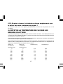
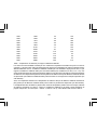
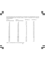
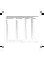
6.6 EFFECT OF AIR TEMPERATURE ON ALTITUDE MEASUREMENT ........................ 42
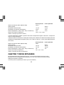
CHAPTER 7 SPARE PARTS AVAILABLE ........................................ 44
CHAPTER 8 ABBREVIATIONS ....................................................... 45
CHAPTER 9 COPYRIGHT AND TRADEMARK NOTICE ................... 45
CHAPTER 10 CE COMPLIANCE ..................................................... 45
CHAPTER 11 LIMITS OF LIABILITY AND ISO 9001 COMPLIANCE 46
CHAPTER 12 DISPOSAL OF THE DEVICE ..................................... 46

6
CHAPTER 1 INTRODUCTION
1.1 GENERAL INFORMATION
The Wristop Computer is a reliable high precision electronic instrument, intended for recreational use. The
outdoor enthusiast who enjoys venturing in sports like skiing, kayaking, mountain climbing, hiking and biking
can rely on the Wristop Computer’s accuracy.
The ergonomically designed Wristop Computer weighs only 2 ounces or 55 grams and is accompanied by a
LCD featuring a large number display intended to be clearly visible in almost any condition.
Note: The Wristop Computer should not be substituted for acquiring measurements that require professional or
industrial precision and should not be used to acquire measurements when skydiving, hang gliding, paragliding,
gyrocopter riding and flying small aircraft.
IMPORTANT NOTE: A PULLOUT PAGE LOCATED ON THE FRONT INSIDE COVER OF THIS MANUAL
GRAPHICALLY ILLUSTRATES AND IDENTIFIES THE PROPERTIES OF THE WRISTOP COMPUTER AND
LCD DISPLAY. THIS PAGE IS DESIGNED TO FACILITATE THE USER’S UNDERSTANDING OF THE
FUNCTIONS AND PROCESSES TO SETUP THOSE FUNCTIONS.
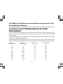
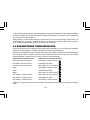
1.2 MAIN FUNCTIONS (MODES)
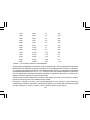
Though the user’s guide applies to all the Wristop Computer models, functions and differences in operation of
the models are noted in the table below.
Functions Wristop Computer Models
Altimax S-Lander Vector X-Lander
Time YES YES YES YES
Altimeter YES YES YES YES
Barometer YES YES YES YES
Compass - - YES YES

7
In each of the functions, associated sub modes provide further enhancements to the usefulness of its owner.
All key features and sub modes are discussed in detail following this section.
Note: Wristop computer models Vector and X-Lander share the same features as well as Altimax and S-
Lander do. The difference is the Vector and Altimax are housed in a sturdy plastic case and the X-Lander and
S-Lander are set in brushed aluminium.
1.2.1 Backlight Features
The Wristop Computer has an electroluminescent backlight. This is initiated by pressing and holding the
[Mode] button for 2 seconds. The backlight will remain on for 5 seconds. Pressing the [Mode] button during
this time will restart the 5 second period, continuing the backlight feature.
1.2.2 Water Resistance
This product is water resistant. Water resistance is tested to 30m/100ft according to ISO 2281 standard
(www.iso.ch).
Note: The Wristop computer is not a dive instrument.
1.3 BUTTON FUNCTIONS
Four buttons are used to operate the Wristop Computer: [Mode], [+] (ON/OFF), [-] (Fast Bearing), and [Select].
1.3.1 The [Mode] Button
Is located on the top right of the Wristop Computer.
• In the main mode level, pressing the [Mode] button allows the user to select or move from one mode or
function to the next (TIME, ALTI, BARO, COMP).
• In the sub mode level, pressing the [Mode] button returns the user to the main mode level.
• In the setup process, pressing the [Mode] button accepts the changes or preferences. Pressing the button
again will return the user to the main mode level.
• Pressing the button for 2 seconds activates the backlight feature.

8
1.3.2 The [+] Button
Is located on the bottom right of the Wristop Computer.
• In the setup process, pressing the [+] button changes or scrolls the value upward.
• In the timing and logbook functions, this button can act as a start/stop (or On/Off) button.
1.3.3 The [-] Button
Is located on the bottom left of the Wristop Computer.
• In the setup process, pressing the [-] button changes or scrolls the value downward.
• For the Vector and X-Lander models this button is also known as the “Fast Bearing” button. Pressing
the [-] button in any of the main modes will quickly display the compass mode, showing either the normal
compass or bearing tracking feature (depending on what display has been chosen in the compass mode).
• For the Altimax and S-Lander models, this button is also called the “Fast Cumulative” button. Pressing the
[-] button in any of the main modes will quickly display the cumulative information of the current logbook
recording.
Note: Details of this feature can be located on Page 26 of this manual.
1.3.4 The [Select] Button
Is located on the top left of the Wristop Computer.
• In the main mode level, pressing the [Select] button allows the user to enter into the sub modes of the
particular function or return to the main mode the user is in.
• In the main mode or sub mode, pressing and holding the [Select] button for more than 2 seconds allows the
user to enter the setup process.
• In the setup process, the [Select] button allows the user to move between settable units or values and
determine preferences.
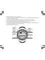
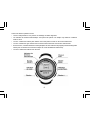
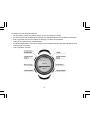
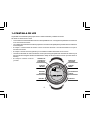
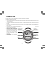
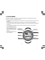
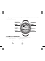
1.4 LCD DISPLAY
The display is designed to offer maximum clarity and simplicity to the user.

9
The display is divided into several regions or areas.
• The Outer Circumference encompasses the outer boundary of the LCD display. The peripheral segments
are found in the Outer Circumference.
• A Barometric Trend Indicator provides a quick reference for forecasting weather conditions.
• Field 1 displays values either numbers or text depending on the mode or sub mode the user is in.
• Field 2 displays large numbers and/or related unit of measure of the function.
• A Mode Indictor Bar displays the main modes (functions) of the Wristop Computer (a triangle arrow located
just below the bar indicates the mode the user is viewing).
• Field 3 displays numbers and/or text.
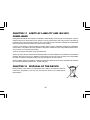
MODE
BUTTON
SELECT
BUTTON
- BUTTON
+ BUTTON
Mode Bar
Indicator
Outer
Circumference
Bubble
Level
Barometer
Trend
Indicator
Field 1
Field 2
Field 3

10
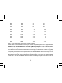
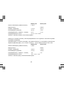
1.5 MEASUREMENTS AND UNITS
The Wristop Computer supplies two units of measure: metric or imperial.
Metric Unit of Measure Imperial Unit of Measure
mft
m/min ft/min
°C °F
mbar inHg
1.5.1 Selecting the Units of Measurement
To change the unit of measure displayed:
1. Check the mode indicator. If the mode arrow is not on TIME, PRESS the [Mode] button until the arrow is
directly below TIME on the Mode Indicator Bar.
2. PRESS the [Mode] and [Select] buttons simultaneously and hold in for 3 seconds. Field 1 will display “SET”
momentarily and then display “UNI” (Fig. 43).
Note: If the user does not press any button for 1 minute in the setup mode, the display will automatically exit
setup.
WARNING: If the user presses the [Select] button (and does not hold for 2 seconds) while in the “UNI” setting
mode, the user will be in the Pressure Sensor Calibration. Refer to the next section for details.
3. PRESS the [Select] button and hold in for 2 seconds. Located to the right in Field 2, “m” or “ft” will begin to
flash.
4. PRESS the [+] button to toggle between “m” and “ft”.
5. At the unit of measure desired, PRESS the [Select] button to move to the next unit. Located below the “m” or
“ft” in Field 2, “mbar” or “inHg” will begin to flash.
6. PRESS the [+] button to toggle between “mbar” and “inHg”.
7. At the unit of measure desired, PRESS the [Select] button to move to the next unit. Located at the top right
in Field 1 (just above the bubble), °C or °F will begin to flash.
8. PRESS the [+] button to toggle between °C and °F.

11
9. At the unit of measure desired, PRESS the [Select] button to move to the next unit. Located at the top
center in Field 1, “m/min” or “ft/min” will begin to flash.
10 PRESS the [+] button to toggle between “m/min” and “ft/min”.
11 At the unit of measure desired, PRESS the [Mode] button to accept the changes. PRESS the [Mode] button
again to return to the main time mode.
Selecting the units of measurement is complete.
1.6 PRESSURE SENSOR CALIBRATION
This is a FACTORY SETTING CALIBRATION. If you are in this mode we highly suggest that you exit this setting
by pressing the [Mode] button. Calibrating this setting will ADVERSELY IMPACT all altitude and barometric
settings of the Wristop Computer.
In this setting, the user will be viewing “SNR” (Sensor) in Field 1. Do not press the [+] or [-] button to adjust the
pressure. Simply exit this setting by pressing the [Select] button to return to the “UNI” setting mode or by
pressing the [Mode] button to return to the main mode.
If the Pressure Setting Calibration has been altered, in error, please contact our Product Support Department.
1.7 CARE AND MAINTENANCE
Perform only the detailed processes discussed in this manual. Do not perform any other service to the
Wristop Computer or attempt to open the case or remove the buttons or the bezel.
Protect your Wristop Computer from shocks, extreme heat and prolonged exposure to direct sunlight. If not in
use, your Wristop Computer should be stored in a clean, dry environment at room temperature.
The Wristop Computer can be wiped clean with a lightly moistened (warm water) cloth. Applying a mild soap to
the area can clean stubborn stains or marks.
Avoid exposing the Wristop Computer to strong chemicals like gasoline, cleaning solvents, acetone, alcohol,
adhesives, and paint, as they will damage the unit’s seals, case and finish.
Never attempt to take the Wristop Computer apart or service it yourself. Make sure the area around the sensors
(backside of the instrument) is kept free of dirt and sand. Never insert any objects into the sensor openings of
the Wristop Computer.

12
1.7.1 Battery Replacement
The Wristop Computer operates on a three-volt lithium cell Type: CR 2430. The maximum life expectancy is
approximately 12-18 months.
A low battery-warning indicator is activated when 5-15 percent of the battery capacity is still available. When
this occurs we recommend replacement of the battery.
Extreme cold weather will activate the low battery-warning indicator. Though the indicator is activated, the
battery may not need to be replaced due to this condition. In temperatures above 10°C (50°F) and the low
battery warning indicator is activated, the battery will need to be replaced.
Note: Heavy use of the electroluminescent backlight, altimeter, and compass will significantly reduce the life of
the battery.
To replace the battery:
1. turn the Wristop Computer to view the backside;
2. insert a coin in the coin slot located on the battery compartment cover;
3. turn the coin counterclockwise to the open position marked on the back of the case;
4. remove the battery compartment cover;
5. remove the old cell from the battery compartment and ensure the o-ring and all surfaces are clean, dry and
not damaged. Do not stretch the o-ring;
6. place the new cell into the battery compartment (negative side down, positive side up);
7. ensure that the o-ring is in its place to keep the Wristop Computer waterproof. Place the battery compartment
cover back onto the backside of the Wristop Computer;
8. insert a coin back into the coin slot; and
9. turn the coin clockwise to the close position marked on the back of the case.
Note: Battery replacement should be performed with extreme care so as to ensure the Wristop Computer
continues to remain waterproof.It is the operator’s responsibility to take due care to ensure that the Wristop
Computer remains waterproof.
After every battery replacement, it is necessary to calibrate the magnetic sensor. Details on performing this
process are found in Calibrating the Compass section of this manual.

13
CHAPTER 2 TIME MODE
The Time Mode provides the user with:
• an adjustable 24/12 hour clock display;
• a calendar pre-programmed to the year 2089; and
• three sub modes: three daily alarms, stopwatch and countdown timer.
To view and use the Time mode:
Check the Mode Indicator Bar. If the mode arrow is not on TIME, PRESS the [Mode] button until the arrow is
directly below TIME on the bar.
In the TIME mode (Fig. 10):
• Field 1 displays the day of the week.
• Field 2 displays the current time.
• Field 3 displays the date (month/day).
• The Outer Circumference graphically displays time in seconds.
The Time mode and all sub modes can be adjusted through the setup program of the Wristop Computer.
2.1 HOW TO SET THE TIME
To set the Time:
1. PRESS the [Select] button and hold in for 2 seconds. Located in Field 3, the seconds will begin to flash
(Fig. 11).
2. PRESS the [+] button to scroll the seconds upward or
PRESS the [-] button to reset the seconds to zero.
3. At the seconds desired, PRESS the [Select] button to move to the next setting. Located on right of Field 2,
the minutes will begin to flash.
4. PRESS the [+] button to scroll the minutes upward or
PRESS the [-] button to scroll the minutes downward.

14
5. At the minutes desired, PRESS the [Select] button to move to the next setting. Located in the center of
Field 2, the hour will begin to flash.
6. PRESS the [+] button to scroll the hour upward or
PRESS the [-] button to scroll the hour downward.
7. At the hour desired, PRESS the [Select] button to move to the next setting. Located in Field 1, the 24 or 12
hour clock setting will begin to flash.
8. PRESS either the [+] or the [-] button to toggle between the 24hr and 12hr.
Note: If the 12 hour clock is chosen either AM/PM will appear below the hour in Field 2.
9. At the clock setting desired, PRESS the [Select] button to move to the next setting. Located in the center of
Field 2, the year will begin to flash (Fig. 12).
10. PRESS the [+] button to scroll the year upward or
PRESS the [-] button to scroll the year downward.
11. At the year desired, PRESS the [Select] button to move to the next setting. Located in the center of Field 3,
the month represented by a number will begin to flash.
12. PRESS the [+] button to scroll the month upward or
PRESS the [-] button to scroll the month downward.
13. At the month desired, PRESS the [Select] button to move to the next setting. Located to the right of Field 3,
the date will begin to flash.
14. PRESS the [+] button to scroll the date upward or
PRESS the [-] button to scroll the date downward.
Note: Once the user has determined the year, month and day, the Wristop Computer will supply the day of the
week in Field 1. The American month/day -view can not be changed to a day/month -view.
15. At the desired date, PRESS the [Mode] button to accept the changes and return to the main mode.
Note: If the user does not press any button for 1 minute in the setup mode, the display will automatically exit
setup.
Setting the time is now complete.

15
2.2 DAILY ALARM SUB MODE
The Wristop Computer allows the user to select and enter settings for up to three alarms.
In the TIME mode, PRESS the [Select] button once to enter this sub mode.
In the Daily Alarm sub mode (Fig. 39) :
• Field 1 displays “ON” or “OFF” (the activation status of a particular alarm),
• Field 2 displays the time of a particular alarm, and
• Field 3 displays the alarm (1, 2, or 3) the user is viewing.
Press the [+] or [-] button to select alarms 1,2, or 3. Then, change the settings in the manner described in the
following section.
2.2.1 How to Set the Daily Alarms
1. PRESS the [+] or the [-] button to select the desired alarm to be set (1,2, or 3).
2. PRESS the [Select] button and hold in for 2 seconds. Located in Field 1, the “ON” or “OFF” will begin to
flash.
3. PRESS either the [+] or the [-] button to toggle between “ON” and “OFF”.
4. At the setting desired, PRESS the [Select] button to move to the next setting. Located in the center of Field
2, the hour will begin to flash.
5. PRESS the [+] button to scroll the hour upward or
PRESS the [-] button to scroll the hour downward.
6. At the hour desired, PRESS the [Select] button to move to the next setting. Located on the right of Field 2,
the minutes will begin to flash.
7. PRESS the [+] button to scroll the minutes upward or
PRESS the [-] button to scroll the minutes downward.
8. At the minutes desired, PRESS the [Mode] button to accept the changes and exit the setup program. A
small bell will appear at the bottom left side in Field 2 to signify an alarm has been activated.
The Alarm setup is complete. To activate up to three alarms, please repeat steps 1-8 for the selected alarm (1,2, or 3).
Note: The Alarm volume can not be changed.

16
2.3 STOPWATCH SUB MODE
The Wristop Computer stopwatch sub mode can provide split time measurement and two finish times up to
23 hours 59 minutes and 59 seconds.
In the TIME mode, PRESS the [Select] button twice to enter this sub mode.
In the Stopwatch sub mode (Fig. 40):
• Field 1 displays the seconds and tenths of a second,
• Field 2 displays the current time, and
• Field 3 displays hours and minutes and to the far right “stopwatch”.
2.3.1 How to Use the Stopwatch
There are three timing modes the user can employ:
• an elapsed time measurement;
• a split time measurement; and
• a two finish time measurement.
In the elapsed time mode:
1. PRESS the [+] button to start, stop, and restart the stopwatch in the stopwatch sub mode.
2. PRESS the [-] button to reset the stopwatch to zero once the stopwatch has stopped.
In the split time mode:
1. PRESS the [+] button to start the stopwatch in the stopwatch sub mode.
2. PRESS the [-] button once to stop the stopwatch and to display a split time.
3. PRESS the [-] button a second time to release the split time display and resume the stopwatch.
4. PRESS the [+] button to stop the stopwatch.
5. PRESS the [-] button to reset the stopwatch to zero once the stopwatch has stopped.

17
In the two finish time mode:
1. PRESS the [+] button to start the stopwatch in the stopwatch sub mode.
2. PRESS the [-] button once to stop the stopwatch to display the finish time of the first person.
3. PRESS the [+] button to stop the stopwatch.
4. PRESS the [-] button a second time to release and display the finish time of the second person.
5. PRESS the [-] button to clear and to reset the stopwatch.
Note: When the stopwatch function is activated, the stopwatch will continue and remain in the background if
the user is in other modes or sub modes. The user can identify the stopwatch is still activated by the flashing
text “stopwatch” in Field 3.
2.4 COUNTDOWN TIMER SUB MODE
In the TIME mode, PRESS the [Select] button three times to enter this sub mode.
In the countdown timer sub mode (Fig. 41):
• Field 1 displays the seconds,
• Field 2 displays the current time, and
• Field 3 displays the hours and minutes and to the bottom far right the text “timer”.

18
2.4.1 How to Set the Countdown Timer
1. PRESS the [Select] button and hold in for 2 seconds. Located in Field 1, the seconds will begin to flash.
2. PRESS the [+] button to scroll the seconds upward or
PRESS the [-] button to scroll the seconds downward.
3. At the seconds desired, PRESS the [Select] button to move to the next setting. Located on right of Field 3,
the minutes will begin to flash.
4. PRESS the [+] button to scroll the minutes upward or
PRESS the [-] button to scroll the minutes downward.
5. At the minutes desired, PRESS the [Select] button to move to the next setting. Located in the center of Field
3, the hour will begin to flash.
6. PRESS the [+] button to scroll the hour upward or
PRESS the [-] button to scroll the hour downward.
7. At the hour desired, PRESS the [Mode] button to accept the changes and exit the setup program.
8. The countdown timer setup is complete.
2.4.2 How to Start the Countdown Timer
To start the countdown timer:
1. PRESS the [+] button to start, stop, and restart the timer in the countdown timer sub mode.
2. PRESS the [-] button to reset the timer to zero once the timer has stopped.
Note: When the countdown timer is activated, the countdown timer will continue and remain in the background
if the user is in other modes or sub modes. The user can identify the countdown timer still activated by the
flashing text “timer” in Field 3.

19
2.5 DUAL TIME SUB MODE (ALTIMAX AND S-LANDER)
Note: This feature applies to the Altimax and S-Lander Wristop Computers
In the TIME mode, PRESS the [Select] button four times to enter this sub mode.
In the dual time mode (Fig. 42):
• Field 1 displays dUA indicating “dual time”,
• Field 2 displays the current time, and
• Field 3 displays the dual time (e.g. your home time).
The user can display the seconds while in this sub mode by pressing the [+] button, in Field 3 the seconds will
appear for 10 seconds. Afterwards the display returns back to showing the dual time.
2.5.1 Setting the Dual Time
In the dual time sub mode:
1. PRESS the [Select] button and hold in for 2 seconds. Located in Field 3, the hours will begin to flash.
2. PRESS the [+] button to scroll the hours upward or
PRESS the [-] button to scroll the hours downward.
3. At the hour desired, PRESS the [Select] button to move to the next setting. Located in Field 3 to the right of
the hour value, the minutes will begin to flash.
4. PRESS the [+] button to scroll the minutes upward or
PRESS the [-] button to scroll the minutes downward.
5. At the minutes desired, PRESS the [Mode] button to accept the changes and exit the setup program.
6. The dual time setup is complete.
The dual time stays the same, even though the time in the main time mode is adjusted. For example, if you set
the dual time to show your home time, your home time will always be displayed in this sub mode even though
you travel to a different time zone and adjust the time in the main time mode.
Note: The dual time function is completely independent and does not affect the alarms or the memory functions.
These are dependent of the current local time.

20
CHAPTER 3 ALTIMETER MODE
The Altimeter mode provides the user with:
• an adjustable unit of measure either meter or feet: meter range -500 to 9,000; ft range -1,600 to 29,500;
• a resolution of 5m or 10ft;
• a display up-date on the rate of vertical movement in intervals of 1 second for 3 minutes, then every 10
seconds or less;
• an automatic 24-hour memory in one hour intervals showing altitude and vertical ascent/descent rate; and
• a logbook, recording approximately 3800 sets of data (one set = altitude, vertical ascent/descent rate and
time).
To view and use the Altimeter mode:
Check the Mode Indicator Bar. If the mode arrow is not on ALTI, PRESS the [Mode] button until the arrow is
directly below ALTI on the bar.
In the ALTIMETER mode (Fig. 1):
• Field 1 displays the vertical ascent or descent rate;
• Field 2 displays the current altitude in increments of 5 meters or 10 feet (depending on the unit of measure
selected); and
• Field 3 displays the current time.
• The Outer Circumference graphically displays the altitude in hundreds of meters or feet over a full thousand
where one complete circle is equivalent to 1000.
IMPORTANT NOTE: IN ORDER TO SET THE ALTITUDE IN THE ALTIMETER MODE, THE ALTITUDE MUST
BE KNOWN. THAT INFORMATION CAN BE FOUND BY UTILIZING A TOPOGRAPHICAL MAP, IDENTIFYING
THE CURRENT LOCATION WITH THE ASSOCIATED ALTITUDE MARKED. THE USER CAN PROCEED
AND FOLLOW THE INSTRUCTIONS, SETTING THE ALTIMETER, PROVIDED IN THE SECTION BELOW.
DETAILS REGARDING THE EFFECT OF AIR TEMPERATURE ON ALTITUDE MEASUREMENT ARE SHOWN
ON PAGE 41 OF THIS MANUAL.
La pagina sta caricando ...
La pagina sta caricando ...
La pagina sta caricando ...
La pagina sta caricando ...
La pagina sta caricando ...
La pagina sta caricando ...
La pagina sta caricando ...
La pagina sta caricando ...
La pagina sta caricando ...
La pagina sta caricando ...
La pagina sta caricando ...
La pagina sta caricando ...
La pagina sta caricando ...
La pagina sta caricando ...
La pagina sta caricando ...
La pagina sta caricando ...
La pagina sta caricando ...
La pagina sta caricando ...
La pagina sta caricando ...
La pagina sta caricando ...
La pagina sta caricando ...
La pagina sta caricando ...
La pagina sta caricando ...
La pagina sta caricando ...
La pagina sta caricando ...
La pagina sta caricando ...
La pagina sta caricando ...
La pagina sta caricando ...
La pagina sta caricando ...
La pagina sta caricando ...
La pagina sta caricando ...
La pagina sta caricando ...
La pagina sta caricando ...
La pagina sta caricando ...
La pagina sta caricando ...
La pagina sta caricando ...
La pagina sta caricando ...
La pagina sta caricando ...
La pagina sta caricando ...
La pagina sta caricando ...
La pagina sta caricando ...
La pagina sta caricando ...
La pagina sta caricando ...
La pagina sta caricando ...
La pagina sta caricando ...
La pagina sta caricando ...
La pagina sta caricando ...
La pagina sta caricando ...
La pagina sta caricando ...
La pagina sta caricando ...
La pagina sta caricando ...
La pagina sta caricando ...
La pagina sta caricando ...
La pagina sta caricando ...
La pagina sta caricando ...
La pagina sta caricando ...
La pagina sta caricando ...
La pagina sta caricando ...
La pagina sta caricando ...
La pagina sta caricando ...
La pagina sta caricando ...
La pagina sta caricando ...
La pagina sta caricando ...
La pagina sta caricando ...
La pagina sta caricando ...
La pagina sta caricando ...
La pagina sta caricando ...
La pagina sta caricando ...
La pagina sta caricando ...
La pagina sta caricando ...
La pagina sta caricando ...
La pagina sta caricando ...
La pagina sta caricando ...
La pagina sta caricando ...
La pagina sta caricando ...
La pagina sta caricando ...
La pagina sta caricando ...
La pagina sta caricando ...
La pagina sta caricando ...
La pagina sta caricando ...
La pagina sta caricando ...
La pagina sta caricando ...
La pagina sta caricando ...
La pagina sta caricando ...
La pagina sta caricando ...
La pagina sta caricando ...
La pagina sta caricando ...
La pagina sta caricando ...
La pagina sta caricando ...
La pagina sta caricando ...
La pagina sta caricando ...
La pagina sta caricando ...
La pagina sta caricando ...
La pagina sta caricando ...
La pagina sta caricando ...
La pagina sta caricando ...
La pagina sta caricando ...
La pagina sta caricando ...
La pagina sta caricando ...
La pagina sta caricando ...
La pagina sta caricando ...
La pagina sta caricando ...
La pagina sta caricando ...
La pagina sta caricando ...
La pagina sta caricando ...
La pagina sta caricando ...
La pagina sta caricando ...
La pagina sta caricando ...
La pagina sta caricando ...
La pagina sta caricando ...
La pagina sta caricando ...
La pagina sta caricando ...
La pagina sta caricando ...
La pagina sta caricando ...
La pagina sta caricando ...
La pagina sta caricando ...
La pagina sta caricando ...
La pagina sta caricando ...
La pagina sta caricando ...
La pagina sta caricando ...
La pagina sta caricando ...
La pagina sta caricando ...
La pagina sta caricando ...
La pagina sta caricando ...
La pagina sta caricando ...
La pagina sta caricando ...
La pagina sta caricando ...
La pagina sta caricando ...
La pagina sta caricando ...
La pagina sta caricando ...
La pagina sta caricando ...
La pagina sta caricando ...
La pagina sta caricando ...
La pagina sta caricando ...
La pagina sta caricando ...
La pagina sta caricando ...
La pagina sta caricando ...
La pagina sta caricando ...
La pagina sta caricando ...
La pagina sta caricando ...
La pagina sta caricando ...
La pagina sta caricando ...
La pagina sta caricando ...
La pagina sta caricando ...
La pagina sta caricando ...
La pagina sta caricando ...
La pagina sta caricando ...
La pagina sta caricando ...
La pagina sta caricando ...
La pagina sta caricando ...
La pagina sta caricando ...
La pagina sta caricando ...
La pagina sta caricando ...
La pagina sta caricando ...
La pagina sta caricando ...
La pagina sta caricando ...
La pagina sta caricando ...
La pagina sta caricando ...
La pagina sta caricando ...
La pagina sta caricando ...
La pagina sta caricando ...
La pagina sta caricando ...
La pagina sta caricando ...
La pagina sta caricando ...
La pagina sta caricando ...
La pagina sta caricando ...
La pagina sta caricando ...
La pagina sta caricando ...
La pagina sta caricando ...
La pagina sta caricando ...
La pagina sta caricando ...
La pagina sta caricando ...
La pagina sta caricando ...
La pagina sta caricando ...
La pagina sta caricando ...
La pagina sta caricando ...
La pagina sta caricando ...
La pagina sta caricando ...
La pagina sta caricando ...
La pagina sta caricando ...
La pagina sta caricando ...
La pagina sta caricando ...
La pagina sta caricando ...
La pagina sta caricando ...
La pagina sta caricando ...
La pagina sta caricando ...
La pagina sta caricando ...
La pagina sta caricando ...
La pagina sta caricando ...
La pagina sta caricando ...
La pagina sta caricando ...
La pagina sta caricando ...
La pagina sta caricando ...
La pagina sta caricando ...
La pagina sta caricando ...
La pagina sta caricando ...
La pagina sta caricando ...
La pagina sta caricando ...
La pagina sta caricando ...
La pagina sta caricando ...
La pagina sta caricando ...
La pagina sta caricando ...
La pagina sta caricando ...
La pagina sta caricando ...
La pagina sta caricando ...
La pagina sta caricando ...
La pagina sta caricando ...
La pagina sta caricando ...
La pagina sta caricando ...
La pagina sta caricando ...
La pagina sta caricando ...
La pagina sta caricando ...
La pagina sta caricando ...
La pagina sta caricando ...
La pagina sta caricando ...
La pagina sta caricando ...
La pagina sta caricando ...
La pagina sta caricando ...
La pagina sta caricando ...
La pagina sta caricando ...
La pagina sta caricando ...
La pagina sta caricando ...
La pagina sta caricando ...
La pagina sta caricando ...
La pagina sta caricando ...
La pagina sta caricando ...
La pagina sta caricando ...
La pagina sta caricando ...
La pagina sta caricando ...
La pagina sta caricando ...
La pagina sta caricando ...
La pagina sta caricando ...
La pagina sta caricando ...
La pagina sta caricando ...
La pagina sta caricando ...
La pagina sta caricando ...
La pagina sta caricando ...
La pagina sta caricando ...
La pagina sta caricando ...
La pagina sta caricando ...
La pagina sta caricando ...
La pagina sta caricando ...
La pagina sta caricando ...
La pagina sta caricando ...
La pagina sta caricando ...
La pagina sta caricando ...
La pagina sta caricando ...
La pagina sta caricando ...
La pagina sta caricando ...
La pagina sta caricando ...
La pagina sta caricando ...
La pagina sta caricando ...
La pagina sta caricando ...
La pagina sta caricando ...
La pagina sta caricando ...
La pagina sta caricando ...
La pagina sta caricando ...
La pagina sta caricando ...
La pagina sta caricando ...
La pagina sta caricando ...
La pagina sta caricando ...
La pagina sta caricando ...
La pagina sta caricando ...
La pagina sta caricando ...
La pagina sta caricando ...
La pagina sta caricando ...
La pagina sta caricando ...
La pagina sta caricando ...
La pagina sta caricando ...
La pagina sta caricando ...
La pagina sta caricando ...
La pagina sta caricando ...
La pagina sta caricando ...
La pagina sta caricando ...
La pagina sta caricando ...
La pagina sta caricando ...
La pagina sta caricando ...
La pagina sta caricando ...
La pagina sta caricando ...
La pagina sta caricando ...
La pagina sta caricando ...
La pagina sta caricando ...
La pagina sta caricando ...
La pagina sta caricando ...
La pagina sta caricando ...
La pagina sta caricando ...
La pagina sta caricando ...
La pagina sta caricando ...
La pagina sta caricando ...
La pagina sta caricando ...
La pagina sta caricando ...
La pagina sta caricando ...
La pagina sta caricando ...
La pagina sta caricando ...
La pagina sta caricando ...
La pagina sta caricando ...
La pagina sta caricando ...
La pagina sta caricando ...
La pagina sta caricando ...
La pagina sta caricando ...
La pagina sta caricando ...
La pagina sta caricando ...
La pagina sta caricando ...
La pagina sta caricando ...
La pagina sta caricando ...
La pagina sta caricando ...
La pagina sta caricando ...
La pagina sta caricando ...
La pagina sta caricando ...
La pagina sta caricando ...
La pagina sta caricando ...
La pagina sta caricando ...
La pagina sta caricando ...
La pagina sta caricando ...
La pagina sta caricando ...
La pagina sta caricando ...
La pagina sta caricando ...
La pagina sta caricando ...
La pagina sta caricando ...
La pagina sta caricando ...
La pagina sta caricando ...
La pagina sta caricando ...
La pagina sta caricando ...
La pagina sta caricando ...
La pagina sta caricando ...
La pagina sta caricando ...
La pagina sta caricando ...
La pagina sta caricando ...
La pagina sta caricando ...
La pagina sta caricando ...
La pagina sta caricando ...
La pagina sta caricando ...
La pagina sta caricando ...
La pagina sta caricando ...
La pagina sta caricando ...
La pagina sta caricando ...
La pagina sta caricando ...
La pagina sta caricando ...
La pagina sta caricando ...
La pagina sta caricando ...
La pagina sta caricando ...
La pagina sta caricando ...
La pagina sta caricando ...
La pagina sta caricando ...
La pagina sta caricando ...
La pagina sta caricando ...
La pagina sta caricando ...
La pagina sta caricando ...
La pagina sta caricando ...
La pagina sta caricando ...
La pagina sta caricando ...
La pagina sta caricando ...
La pagina sta caricando ...
La pagina sta caricando ...
La pagina sta caricando ...
La pagina sta caricando ...
La pagina sta caricando ...
La pagina sta caricando ...
La pagina sta caricando ...
La pagina sta caricando ...
-
 1
1
-
 2
2
-
 3
3
-
 4
4
-
 5
5
-
 6
6
-
 7
7
-
 8
8
-
 9
9
-
 10
10
-
 11
11
-
 12
12
-
 13
13
-
 14
14
-
 15
15
-
 16
16
-
 17
17
-
 18
18
-
 19
19
-
 20
20
-
 21
21
-
 22
22
-
 23
23
-
 24
24
-
 25
25
-
 26
26
-
 27
27
-
 28
28
-
 29
29
-
 30
30
-
 31
31
-
 32
32
-
 33
33
-
 34
34
-
 35
35
-
 36
36
-
 37
37
-
 38
38
-
 39
39
-
 40
40
-
 41
41
-
 42
42
-
 43
43
-
 44
44
-
 45
45
-
 46
46
-
 47
47
-
 48
48
-
 49
49
-
 50
50
-
 51
51
-
 52
52
-
 53
53
-
 54
54
-
 55
55
-
 56
56
-
 57
57
-
 58
58
-
 59
59
-
 60
60
-
 61
61
-
 62
62
-
 63
63
-
 64
64
-
 65
65
-
 66
66
-
 67
67
-
 68
68
-
 69
69
-
 70
70
-
 71
71
-
 72
72
-
 73
73
-
 74
74
-
 75
75
-
 76
76
-
 77
77
-
 78
78
-
 79
79
-
 80
80
-
 81
81
-
 82
82
-
 83
83
-
 84
84
-
 85
85
-
 86
86
-
 87
87
-
 88
88
-
 89
89
-
 90
90
-
 91
91
-
 92
92
-
 93
93
-
 94
94
-
 95
95
-
 96
96
-
 97
97
-
 98
98
-
 99
99
-
 100
100
-
 101
101
-
 102
102
-
 103
103
-
 104
104
-
 105
105
-
 106
106
-
 107
107
-
 108
108
-
 109
109
-
 110
110
-
 111
111
-
 112
112
-
 113
113
-
 114
114
-
 115
115
-
 116
116
-
 117
117
-
 118
118
-
 119
119
-
 120
120
-
 121
121
-
 122
122
-
 123
123
-
 124
124
-
 125
125
-
 126
126
-
 127
127
-
 128
128
-
 129
129
-
 130
130
-
 131
131
-
 132
132
-
 133
133
-
 134
134
-
 135
135
-
 136
136
-
 137
137
-
 138
138
-
 139
139
-
 140
140
-
 141
141
-
 142
142
-
 143
143
-
 144
144
-
 145
145
-
 146
146
-
 147
147
-
 148
148
-
 149
149
-
 150
150
-
 151
151
-
 152
152
-
 153
153
-
 154
154
-
 155
155
-
 156
156
-
 157
157
-
 158
158
-
 159
159
-
 160
160
-
 161
161
-
 162
162
-
 163
163
-
 164
164
-
 165
165
-
 166
166
-
 167
167
-
 168
168
-
 169
169
-
 170
170
-
 171
171
-
 172
172
-
 173
173
-
 174
174
-
 175
175
-
 176
176
-
 177
177
-
 178
178
-
 179
179
-
 180
180
-
 181
181
-
 182
182
-
 183
183
-
 184
184
-
 185
185
-
 186
186
-
 187
187
-
 188
188
-
 189
189
-
 190
190
-
 191
191
-
 192
192
-
 193
193
-
 194
194
-
 195
195
-
 196
196
-
 197
197
-
 198
198
-
 199
199
-
 200
200
-
 201
201
-
 202
202
-
 203
203
-
 204
204
-
 205
205
-
 206
206
-
 207
207
-
 208
208
-
 209
209
-
 210
210
-
 211
211
-
 212
212
-
 213
213
-
 214
214
-
 215
215
-
 216
216
-
 217
217
-
 218
218
-
 219
219
-
 220
220
-
 221
221
-
 222
222
-
 223
223
-
 224
224
-
 225
225
-
 226
226
-
 227
227
-
 228
228
-
 229
229
-
 230
230
-
 231
231
-
 232
232
-
 233
233
-
 234
234
-
 235
235
-
 236
236
-
 237
237
-
 238
238
-
 239
239
-
 240
240
-
 241
241
-
 242
242
-
 243
243
-
 244
244
-
 245
245
-
 246
246
-
 247
247
-
 248
248
-
 249
249
-
 250
250
-
 251
251
-
 252
252
-
 253
253
-
 254
254
-
 255
255
-
 256
256
-
 257
257
-
 258
258
-
 259
259
-
 260
260
-
 261
261
-
 262
262
-
 263
263
-
 264
264
-
 265
265
-
 266
266
-
 267
267
-
 268
268
-
 269
269
-
 270
270
-
 271
271
-
 272
272
-
 273
273
-
 274
274
-
 275
275
-
 276
276
-
 277
277
-
 278
278
-
 279
279
-
 280
280
-
 281
281
-
 282
282
-
 283
283
-
 284
284
-
 285
285
-
 286
286
-
 287
287
-
 288
288
-
 289
289
-
 290
290
-
 291
291
-
 292
292
-
 293
293
-
 294
294
-
 295
295
-
 296
296
-
 297
297
-
 298
298
-
 299
299
-
 300
300
-
 301
301
-
 302
302
-
 303
303
-
 304
304
-
 305
305
-
 306
306
-
 307
307
-
 308
308
-
 309
309
-
 310
310
-
 311
311
-
 312
312
-
 313
313
-
 314
314
-
 315
315
-
 316
316
-
 317
317
-
 318
318
-
 319
319
-
 320
320
-
 321
321
-
 322
322
-
 323
323
-
 324
324
-
 325
325
-
 326
326
-
 327
327
-
 328
328
-
 329
329
-
 330
330
-
 331
331
-
 332
332
-
 333
333
-
 334
334
-
 335
335
-
 336
336
-
 337
337
-
 338
338
-
 339
339
-
 340
340
-
 341
341
-
 342
342
-
 343
343
-
 344
344
-
 345
345
-
 346
346
-
 347
347
-
 348
348
-
 349
349
-
 350
350
-
 351
351
-
 352
352
-
 353
353
-
 354
354
-
 355
355
-
 356
356
-
 357
357
-
 358
358
-
 359
359
-
 360
360
-
 361
361
-
 362
362
-
 363
363
-
 364
364
-
 365
365
-
 366
366
-
 367
367
-
 368
368
-
 369
369
-
 370
370
-
 371
371
-
 372
372
-
 373
373
-
 374
374
-
 375
375
-
 376
376
-
 377
377
-
 378
378
-
 379
379
-
 380
380


in altre lingue
- français: Suunto Altimax Manuel utilisateur
- español: Suunto Altimax Manual de usuario
- Deutsch: Suunto Altimax Benutzerhandbuch
- Nederlands: Suunto Altimax Handleiding
- eesti: Suunto Altimax Kasutusjuhend
- svenska: Suunto Altimax Användarmanual
Documenti correlati
-
Suunto Advizor Manuale del proprietario
-
Suunto MARINER | REGATTA | YACHTSMAN Manuale utente
-
-
Suunto EN | FR | DE | ES | IT | NL | FI | SV Manuale utente
-
Suunto OBSERVER ST Manuale del proprietario
-
Suunto S6 Manuale utente
-
Suunto GPS POD Manuale del proprietario
-
-
-
Altri documenti
-
Bushnell Digital Compass 700102 Manuale utente
-
-
-
-
Freestyle Nomad Manuale utente
-
-
-
-
-