American Dynamics MegaPower LT specificazione
- Tipo
- specificazione

MegaPower
TM
LT
Matrix Switcher/Controller System
ADMPLT16
ADMPLT32
ADMPLT16C2
ADMPLT16C3
ADMPLT32C2
ADMPLT32C3
Installation and Operation Instructions

ii
MegaPower LT
Notice
The information in this manual was current when published. The manufacturer reserves the right to
revise and improve its products. All specifications are therefore subject to change without notice.
Copyright
Under copyright laws, the contents of this manual may not be copied, photocopied, reproduced,
translated or reduced to any electronic medium or machine-readable form, in whole or in part,
without prior written consent of American Dynamics Video Products Division.
© Copyright 2003
American Dynamics Video Products Division
6795 Flanders Drive San Diego, CA 92121 U.S.A.
Trademarks
MegaPower
™
is a trademark of American Dynamics Video Products Division.
Trademarked names are used throughout this manual. Rather than place a symbol at each occurrence,
trademarked names are designated with initial capitalization. Inclusion or exclusion is not a judgment
on the validity or legal status of the term.
Important Information
Before proceeding, please read and observe all instructions and warnings contained in this manual.
Retain this manual with the original bill of sale for future reference and, if necessary, warranty
service.
When unpacking your new American Dynamics product, check for missing or damaged items. If
any item is missing, or if damage is evident, DO NOT INSTALL OR OPERATE THIS PRODUCT.
Contact your dealer for assistance.
NOTE
This product is supplied with a printed English manual. The manual is also provided in other
languages (French, Spanish and German) on the included CD.
For your Records
Complete the following product purchase information. The factory requests this information when
contacted for technical support. It is also valuable in case of loss or theft.
Purchase Date: __________________________
Serial Number: __________________________

iii
Matrix Installation and Operation
INSTALLATION IS ONLY TO BE CARRIED OUT BY COMPETENT, QUALIFIED AND EXPERIENCED PERSONNEL.
WIRE IN ACCORDANCE WITH COUNTRY OF INSTALLATION NATIONAL WIRING REGULATIONS.
ACCESS CAN ONLY BE GAINED BY SERVICE PERSONS. THERE ARE NO USER-ACCESS AREAS. ACCESS
BY SERVICE PERSONS CAN ONLY BE GAINED BY THE USE OF AN APPROPRIATE TOOL.
THE EQUIPMENT SUPPLIED WITH THIS MANUAL IS DESIGNED FOR USE IN GENERAL PURPOSE CCTV
INSTALLATION AND HAS NO OTHER FUNCTION. DO NOT EXCEED THE VOLTAGE AND TEMPERATURE
LIMITS GIVEN IN THE SPECIFICATIONS. ONLY USE YOUR MATRIX IN A CLEAN, DRY, DUST-FREE
ENVIRONMENT.
TO REDUCE RISK OF ELECTRIC SHOCK, DO NOT REMOVE COVER. NO USER SERVICEABLE PARTS INSIDE.
REFER SERVICING TO QUALIFIED SERVICE PERSONNEL.
TO PREVENT FIRE OR SHOCK HAZARD, DO NOT EXPOSE THIS APPLIANCE TO RAIN OR MOISTURE.
THE MEGAPOWER LT MUST ONLY BE POWERED BY THE CLASS 2 INSULATED UL LISTED 15 WATT LPS
SUPPLY (MP-PSU) PROVIDED.
POWER ISOLATION MUST BE PROVIDED VIA THE: PLUG; APPLIANCE COUPLER; ISOLATING SWITCH;
CIRCUIT BREAKER, OR AN EQUIVALENT ELECTRICAL DEVICE IN CLOSE PROXIMITY TO THE EQUIPMENT.
A 3 AMP FUSE IN THE UK PLUG PROVIDES PROTECTION AGAINST OVERLOAD AND SHORT CIRCUIT. IN
AREAS WHERE A UK PLUG IS NOT APPROPRIATE, SIMILIAR PROTECTION MUST BE PROVIDED IN THE
INSTALLATION.
Electrical Safety
British Standard BSEN60950:2001 Safety of information technology equipment Including electrical business
equipment.
Underwriters Laboratories Inc. UL1950 Safety of information technology equipment, including electrical business
equipment.
Canadian Standards Association CAN/CSA C22.2 No. 950-95.
Radio Frequency Emissions
British Standard EN50081-1:1992 Electromagnetic compatibility - Emission. Part 1. Residential, commercial and
light industry.
British Standard BSEN55022:1998 Limits and methods of measurement of radio disturbance characteristics of
information technology equipment.
Immunity
British Standard BSEN50130-4 Alarm Systems Part 4 Electromagnetic compatibility Product family standard: Im-
munity requirements for components of fire, intruder and social alarm systems.
EU Conformance Statement
A Declaration of Conformity in accordance with the above EU standards has been made and is on file with the
manufacturer. The manufacturer declares that the product supplied with this document is complaint with the provi-
sions of the EMC Directive 89/336 EEC, the Low Voltage Directive LVD 73/23 EEC, the CE Marking Directive 93/68
EEC and all associated amendments.
Regulatory Notices
This device complies with part 15 of the FCC rules. Operation is subject to the following two conditions: (1) This
device may not cause harmful interference, and (2) this device must accept any interference received, including
interference that may cause undesired operation.

iv
MegaPower LT
L’INSTALLATION NE SAURAIT ÊTRE EFFECTUÉE QUE PAR UN PERSONNEL QUALIFIÉ ET EXPÉRIMENTÉ. BRANCHER
ET RACCORDER EN CONFORMITÉ AVEC LES RÉGLEMENTATIONS EN VIGUEUR DANS LE PAYS OÙ EST INSTALLÉE
L’UNITÉ.
L’ACCÈS NE PEUT ÊTRE OBTENU QUE PAR LES TECHNICIENS DE MAINTENANCE. L’ACCÈS DOIT ÊTRE
STRICTEMENT INTERDIT À TOUT UTILISATEUR. L’ACCÈS PAR LES TECHNICIENS DE MAINTENANCE NE PEUT
ÊTRE EFFECTUÉ QU’À L’AIDE D’UN OUTIL APPROPRIÉ.
L’ÉQUIPEMENT FOURNI AVEC LE PRÉSENT MANUEL EST CONÇU POUR ÊTRE UTILISÉ DANS LE CADRE GÉNÉRAL
DE LA SURVEILLANCE PAR CAMÉRA À CIRCUIT FERMÉ (CCTV) ET N’A AUCUNE AUTRE FONCTION. NE PAS
DÉPASSER LES SEUILS DE TENSION ET DE TEMPÉRATURE INDIQUÉS DANS LES CARACTÉRISTIQUES
TECHNIQUES. N’UTILISER L’UNITÉ MATRIX QU’EN ENVIRONNEMENT PROPRE, SEC ET EXEMPT DE POUSSIÈRE.
POUR RÉDUIRE LES RISQUES D’ÉLECTROCUTION, NE PAS DÉPOSER LE COUVERCLE. AUCUN COMPOSANT NE
PEUT ÊTRE RÉPARÉ PAR L’UTILISATEUR. FAIRE APPEL À UN TECHNICIEN DE MAINTENANCE COMPÉTENT.
POUR PRÉVENIR TOUT RISQUE D’INCENDIE OU D’ÉLECTROCUTION, NE PAS EXPOSER CETTE UNITÉ À LA PLUIE
NI À L’HUMIDITÉ.
L’UNITÉ MEGAPOWER LT DOIT ÊTRE ALIMENTÉE PAR LE GROUPE DE CLASSE 2 UL ISOLÉ 15 WATTS (MP-PSU)
FOURNI.
L’ISOLATION DOIT ÊTRE ASSURÉE PAR LE BIAIS DE LA PRISE, DU COUPLEUR DE L’UNITÉ, DU COMMUTATEUR
ISOLANT, DU FUSIBLE PI DE TOUT DISPOSITIF ÉLECTRIQUE ÉQUIVALENT À PROXIMITÉ RAPPROCHÉE DE L’UNITÉ.
UN FUSIBLE DE 3 A DANS LA PRISE BRITANNIQUE ASSURE LA PROTECTION CONTRE LES SURCHARGES ET LES
COURTS-CIRCUITS. DANS LES PAYS OÙ UNE PRISE BRITANNIQUE NE CONVIENT PAS, UNE PROTECTION SIMILAIRE
DOIT ÊTRE APPORTÉE LORS DE L’INSTALLATION.
Sécurité électrique
Norme britannique BSEN60950:2001 : sécurité des équipements informatiques, notamment les équipements électriques
commerciaux.
Underwriters Laboratories Inc. UL1950 – Sécurité des équipements informatiques, y compris les équipements électriques à
usage professionnel.
Canadian Standards Association CAN/CSA C22.2 No. 950-95.
Émission de fréquences radio
Norme européenne EN50081-1:1992 – Compatibilité électromagnétique - Émissions. Section 1. Usage résidentiel, commercial
et industriel limité.
Norme britannique BSEN55022:1998 : limites et méthodes de mesure des caractéristiques de perturbation radio des
équipements informatiques.
Immunité
Norme britannique BSEN50130-4 : systèmes d’alarme, 4e partie, compatibilité électromagnétique Norme de famille de produits :
caractéristiques d’immunité des composants des systèmes anti-incendie, anti-intrusion et d’alarme sociaux.
Déclaration de conformité UE
Une déclaration de conformité aux normes ci-dessus de l’Union européenne a été réalisée et est conservée chez le constructeur.
Le constructeur déclare le produit accompagnant ce document conforme aux dispositions de la Directive 89/336 de la CEE
sur la compatibilité électromagnétique, de la directive LVD 73/23 de la CEE sur les basses tensions et de la Directive 93/68
de la CEE et ses modifications sur la marque CE.
Avis réglementaires
Cet équipement est conforme au paragraphe 15 des réglementations de la FCC. Son utilisation est sujette aux deux conditions
suivantes : (1) cet équipement ne doit pas générer d’interférences nuisibles et (2) cet équipement doit accepter les interférences
éventuelles, notamment les interférences susceptibles de provoquer un fonctionnement indésirable.

v
Matrix Installation and Operation
DIE INSTALLATION DARF NUR VON KOMPETENTEM, QUALIFIZIERTEM UND ERFAHRENEM PERSONAL AUSGEFÜHRT
WERDEN. DIE VERKABELUNG MUSS GEMÄSS DER AM INSTALLATIONSORT GELTENDEN, NATIONALEN
VERKABELUNGSVORSCHRIFTEN ERFOLGEN.
DER ZUGRIFF IST NUR DEM WARTUNGSPERSONAL MÖGLICH. ES SIND KEINE BENUTZERZUGÄNGLICHEN
BEREICHE VORHANDEN. DER ZUGRIFF DURCH DAS WARTUNGSPERSONAL IST NUR MIT HILFE EINES GEEIGNETEN
WERKZEUGS MÖGLICH.
DIE ZUSAMMEN MIT DIESEM HANDBUCH GELIEFERTE AUSRÜSTUNG IST FÜR DEN GEBRAUCH IN ALLGEMEINEN
CCTV-ANLAGEN KONZIPIERT UND DIENT KEINEM ANDEREN ZWECK. DIE IN DEN TECHNISCHEN DATEN
ANGEGEBENEN SPANNUNGS- UND TEMPERATURGRENZEN DÜRFEN NICHT ÜBERSCHRITTEN WERDEN. DIE
SCHALTMATRIX DARF NUR IN EINER SAUBEREN, TROCKENEN UND STAUBFREIEN UMGEBUNG VERWENDET
WERDEN.
UM DAS RISIKO VON STROMSCHLAG ZU REDUZIEREN, DARF DIE ABDECKUNG NICHT ENTFERNT WERDEN. DAS
GERÄT ENTHÄLT KEINE DURCH DEN BENUTZER WARTBARE TEILE. WARTUNGSARBEITEN DÜRFEN NUR VON
QUALIFIZIERTEM WARTUNGSPERSONAL DURCHGEFÜHRT WERDEN.
ZUM SCHUTZ GEGEN BRAND- ODER STROMSCHLAGGEFAHR DARF DAS GERÄT KEINEM REGEN ODER
FEUCHTIGKEIT AUSGESETZT WERDEN.
DAS MEGAPOWER-LT-SYSTEM DARF NUR ÜBER DIE MITGELIEFERTE, ISOLIERTE, UL-GELISTET 15-WATT-
VERSORGUNG (MP-PSU) GESPEIST WERDEN.
DIE STROMVERSORGUNG MUSS MITTELS DES FOLGENDEN UNTERBROCHEN WERDEN KÖNNEN: STECKER;
GERÄTEKUPPLUNG; TRENNSCHALTER; SICHERUNG ODER EINE GLEICHWERTIGE ELEKTRISCHE VORRICHTUNG
IN DER NÄHE DER AUSRÜSTUNG.
EINE IM BRITISCHEN NETZSTROMSTECKER UNTERGEBRACHTE 3-AMPERE-SICHERUNG SICHERT DIE
AUSRÜSTUNG GEGEN ÜBERLASTUNG UND KURZSCHLUSS. WO EIN BRITISCHER STECKER NICHT ANGEBRACHT
IST, MUSS EIN ÄHNLICHER SCHUTZ ÜBER DIE INSTALLATION ERFOLGEN.
Elektrische Sicherheit
British Standard BSEN60950:2001 – Sicherheit von informationstechnischer Ausrüstung, einschließlich elektrischer
Geschäftsausrüstung.
Underwriters Laboratories Inc. UL1950 Sicherheit von informationstechnischer Ausrüstung, einschließlich elektrischer
Geschäftsausrüstung.
Canadian Standards Association CAN/CSA C22.2 No. 950-95.
Funkfrequenzemissionen
Euronorm EN50081-1:1992 Elektromagnetische Kompatibilität – Emission. Teil 1. Wohnbereiche, kommerzielle und
leichtindustrielle Umgebungen.
British Standard BSEN55022:1998 – Messgrenzen und -verfahren für Funkstörungscharakteristiken von
informationstechnischer Ausrüstung.
Immunität
British Standard BSEN50130-4 – Alarmsysteme, Teil 4, elektromagnetischer Kompatibilitätsstandard für die Produktgruppe:
Immunitätsanforderungen für Komponenten von Feuer-, Einbruchs- und öffentlichen Alarmsystemen.
EU-Konformitätserklärung
Eine Konformitätserklärung gemäß der o. g. EU-Standards ist erfolgt und liegt beim Hersteller vor. Der Hersteller erklärt,
dass das mit diesem Dokument gelieferte Produkt die Anforderungen der Richtlinie für elektromagnetische Kompatibilität
89/336 EEC, der Richtlinie für Niederspannung LVD 73/23 EEC, der CE-Kennzeichnungsrichtlinie 93/68 EEC und aller
diesbezüglichen Änderungen erfüllt.
Aufsichtsbehördliche Hinweise
Dieses Gerät entspricht Teil 15 der FCC-Richtlinien. Der Betrieb ist vorbehaltlich der beiden folgenden Bedingungen gestattet:
(1) dieses Gerät darf keine schädlichen Störungen verursachen, und (2) dieses Gerät muss alle Störungen akzeptieren,
einschließlich solcher, die den Betrieb beeinträchtigen könnten.

vi
MegaPower LT
L’INSTALLAZIONE DEVE ESSERE ESEGUITA ESCLUSIVAMENTE DA PERSONALE COMPETENTE, ESPERTO E
QUALIFICATO. COLLEGARE I CAVI IN CONFORMITÀ ALLE SPECIFICHE NAZIONALI DI INSTALLAZIONE.
L’ACCESSO È CONSENTITO SOLTANTO AL PERSONALE ADDETTO ALLA MANUTENZIONE. NON ESISTONO AREE
ACCESSIBILI DA PARTE DELL’UTENZA. IL PERSONALE ADDETTO ALLA MANUTENZIONE PUÒ ACCEDERE SOLO
UTILIZZANDO UNO STRUMENTO APPROPRIATO.
L’APPARECCHIO CUI QUESTO MANUALE SI RIFERISCE È DESTINATO ALL’USO IN INSTALLAZIONI GENERICHE PER
TV A CIRCUITO CHIUSO E NON HA ALCUNA ALTRA FUNZIONE. NON SUPERARE I LIMITI DI VOLTAGGIO E
TEMPERATURA INDICATI NELLE SPECIFICHE. USARE L’APPARECCHIO ESCLUSIVAMENTE IN AMBIENTI PULITI,
NON UMIDI E NON POLVEROSI.
PER RIDURRE IL RISCHIO DI SHOCK ELETTRICI, NON RIMUOVERE IL COPERCHIO. L’INTERNO NON CONTIENE
PARTI CHE L’UTENTE POSSA RIPARARE. RIVOLGERSI A TECNICI DI ASSISTENZA QUALIFICATI.
PER EVITARE IL RISCHIO DI INCENDI O SHOCK, NON ESPORRE L’APPARECCHIO ALLA PIOGGIA O ALL’UMIDITÀ.
IL SISTEMA MEGAPOWER LT DEVE ESSERE ALIMENTATO ESCLUSIVAMENTE CON L’ALIMENTATORE ISOLATO DI
CLASSE 2 (CERTIFICATO UL) A 15 WATT (MP-PSU) ACCLUSO.
PER L’ISOLAMENTO ELETTRICO, SERVIRSI DI: SPINA, ACCOPPIATORE DEL DISPOSITIVO, INTERRUTTORE
ISOLANTE, INTERRUTTORE DI CIRCUITO O DI UN DISPOSITIVO ELETTRICO EQUIVALENTE, INSTALLATO VICINO
ALL’APPARECCHIO,
ALL’INTERNO DELLA SPINA DI TIPO BRITANNICO È PRESENTE UN FUSIBILE DA 3 AMPERE, CHE PROTEGGE DA
SOVRACCARICHI E CORTI CIRCUITI. NEI PAESI IN CUI TALE SPINA NON È UTILIZZABILE, AL MOMENTO
DELL’INSTALLAZIONE SI DEVE PREVEDERE UNA PROTEZIONE ANALOGA.
Sicurezza elettrica
Standard britannico BSEN60950:2001 per la sicurezza delle apparecchiature informatiche, incluse le apparecchiature
elettriche aziendali.
Underwriters Laboratories Inc. UL1950 per la sicurezza delle apparecchiature informatiche, incluse le apparecchiature
elettriche aziendali.
Associazione standard canadesi CAN/CSA C22.2 No. 950-95.
Emissioni in radiofrequenza
Standard europeo EN50081-1:1992, compatibilità elettromagnetica - emissioni. Parte 1. Installazioni residenziali, commerciali
e dell’industria leggera.
Standard britannico BSEN55022:1998 per i limiti e i metodi di misurazione delle interferenze radio caratteristiche delle
apparecchiature informatiche.
Inalterabilità
Standard britannico BSEN50130-4 per i sistemi di allarme, parte 4, standard di compatibilità elettromagnetica per la
tipologia di prodotti: requisiti di immunità per sistemi di allarme antincendio, anti-intrusione e di tipo sociale.
Dichiarazione di conformità UE
In base agli standard UE summenzionati, è stata emessa una Dichiarazione di conformità che è archiviata nella sede del
produttore. Il produttore dichiara che il prodotto fornito col presente documento è conforme alle prescrizioni della direttiva
EMC 89/336 CEE, della direttiva sul basso voltaggio LVD 73/23 CEE, della direttiva sul marchio CE 93/68 CEE e di tutte
le relative modifiche.
Avvisi normativi
Questo dispositivo è conforme alle norme FCC, parte 15. Il funzionamento è soggetto alle due condizioni seguenti: (1) Il
dispositivo non deve causare interferenze dannose; (2) il dispositivo deve sostenere le interferenze in ingresso, incluse
quelle che potrebbero determinare un funzionamento non desiderato.

vii
Matrix Installation and Operation
LA INSTALACIÓN DEBERÁ SER REALIZADA EXCLUSIVAMENTE POR PERSONAL COMPETENTE, CUALIFICADO Y
CON EXPERIENCIA. LAS CONEXIONES ELÉCTRICAS SE REALIZARÁN EN CONFORMIDAD CON LA NORMATIVA
NACIONAL EN MATERIA DE CABLEADO DE CADA PAÍS.
ACCESO SÓLO AUTORIZADO AL PERSONAL DEL SERVICIO TÉCNICO. NO HAY ZONAS DE ACCESO PARA USUARIOS.
EL PERSONAL DEL SERVICIO TÉCNICO SOLAMENTE PODRÁ ACCEDER MEDIANTE EL USO DE UNA HERRAMIENTA
ADECUADA.
EL EQUIPO QUE SE SUMINISTRA JUNTO CON ESTE MANUAL ESTÁ DISEÑADO PARA USO EN INSTALACIONES DE
CCTV (CIRCUITO CERRADO DE TELEVISIÓPN) DE PROPÓSITO GENERAL Y NO TIENE OTRA FUNCIÓN. NO SUPERE
LOS LÍMITES DE TENSIÓN Y TEMPERATURA INDICADOS EN LAS ESPCIFICACIONES. USE LA MATRIZ SOLAMENTE
EN UN AMBIENTE LIMPIO, SECO Y SIN POLVO.
CON EL FIN DE REDUCIR EL RIESGO DE DESCARGA ELÉCTRICA, EVITE RETIRAR LA CUBIERTA. EN EL INTERIOR
NO HAY NINGÚN COMPONENTE QUE PUEDA SER REPARADO POR EL USUARIO. CUALQUIER REPARACIÓN DEBE
SER REALIZADA POR PERSONAL DE SERVICIO DEBIDAMENTE CUALQUIDFICADO.
PARA EVITAR RIESGO DE INCENDIO O DESCARGA ELÉCTRICA, NO EXPONGA ESTE EQUIPO A LA LLUVIA O A LA
HUMEDAD.
EL MEGAPOWER LT DEBE ALIMENTARSE EXCLUSIVAMENTE CON LA FUENTE DE ALIMENTACIÓN (MP-PSU) DE
15 VATIOS, CON AISLAMIENTO INCLUIDA EN LA LISTA UL DE CLASE 2, QUE SE SUMINISTRA CON EL EQUIPO.
EL AISLAMIENTO DE LA ALIMENTACIÓN DEBE REALIZARSE POR MEDIO DE: CONECTOR; ACOPLADOR DEL EQUIPO;
CONMUTADOR DE AISLAMIENTO; DISYUNTOR, O UN DISPOSITIVO ELÉCTRICO EQUIVALENTE SITUADO MUY
PRÓXIMO AL EQUIPO.
EN EL CONECTOR DEL REINO UNIDO, UN FUSIBLE DE 3 A PROPORCIONA PROTECCIÓN CONTRA SOBRECARGA Y
CORTOCIRCUITO. EN LOS LUGARES EN QUE NO SE PUEDEN UTILIZAR CONECTORES DEL REINO UNIDO, SE
DEBE EMPLEAR UNA PROTECCIÓN SIMILAR EN LA INSTALACIÓN.
Seguridad eléctrica
British Standard BSEN60950:2001 Seguridad de equipos informáticos, incluidos equipos eléctricos de uso empresarial.
Underwriters Laboratories Inc. UL1950 Seguridad de equipos informáticos, incluidos equipos eléctricos de uso empresarial.
Canadian Standards Association CAN/CSA C22.2 Nº 950-95.
Emisión de radiofrecuencia
European Standard EN50081-1:1992 Comaptibilidad electromagnética - Emisión. Parte 1. Residencial, comercial e industria
ligera.
British Standard BSEN55022:1998 Límites y métodos de medición de características de interferencias de radio para
equipos informáticos.
Inmunidad
British Standard BSEN50130-4, Parte 4 de sistemas de alarma (Alarm Systems), estándar de compatibilidad
electromagnética para familia de productos: Requisitos de inmunidad para componentes de sistemas de alarma
antiincendios, contra intrusión y sociales.
Declaración de Conformidad de la UE
Se ha realizado la Declaración de conformidad en cumplimiento de las normas de la UE indicadas más arriba. El fabricante
es el depositario de dicha declaración. El fabricante declara que el producto suministrado con esta documentación cumple
las normas estipuladas por la Directiva sobre EMC 89/336 CEE, la Directiva sobre baja tensión LVD 73/23 CEE, la
directiva sobre Marca CE 93/68 CEE y todas las enmiendas asociadas a éstas.
Avisos sobre cumplimiento de la legislación
Este dispositivo cumple la parte 15 de las normas de la FCC. Su utilización está sujeta a las siguientes dos condiciones: (1)
Este equipo no puede provocar interferencias nocivas, y (2) este equipo debe aceptar cualquier interferencia recibida, incluidas
las interferencias que puedan provocar un funcionamiento no deseado.

viii
MegaPower LT
DE INSTALLATIE DIENT ALLEEN TE WORDEN UITGEVOERD DOOR DESKUNDIG, GEKWALIFICEERD EN ERVAREN
PERSONEEL. INSTALLEER VOLGENS DE TER PLEKKE GELDENDE AANSLUITRICHTLIJNEN.
TOEGANG ALLEEN MOGELIJK DOOR SERVICEPERSONEEL. GEEN TOEGANG VOOR EINDGEBRUIKERS.
SERVICEMEDEWERKERS KUNNEN ALLEEN TOEGANG VERKRIJGEN MET BEHULP VAN DAARVOOR GESCHIKT
GEREEDSCHAP.
DE BIJ DEZE HANDLEIDING GELEVERDE APPARATUUR IS ONTWORPEN VOOR GEBRUIK IN ALGEMENE CCTV-
INSTALLATIES EN HEEFT VERDER GEEN ANDERE FUNCTIE. STEL DE APPARATUUR NIET BLOOT AAN VOLTAGES
EN TEMPERATUREN BOVEN DE AANGEGEVEN LIMIET. GEBRUIK UW MATRIX ALLEEN IN EEN SCHONE, DROGE,
STOFVRIJE OMGEVING.
OM DE KANS OP ELEKTRISCHE SCHOKKEN TE VERMIJDEN, DIENT U DE KAP NIET TE VERWIJDEREN. HET APPARAAT
BEVAT GEEN ONDERDELEN DIE DOOR DE GEBRUIKER KUNNEN WORDEN GEREPAREERD. LAAT ONDERHOUD
UITVOEREN DOOR GEKWALIFICEERD ONDERHOUDSPERSONEEL.
OM DE KANS OP BRAND OF ELEKTRISCHE SCHOKKEN TE VERMIJDEN, DIENT U DIT APPARAAT NIET AAN REGEN
OF VOCHT BLOOT TE STELLEN.
DE MEGAPOWER LT MAG ALLEEN WORDEN AANGESLOTEN OP DE MEEGELEVERDE, GEÏSOLEERDE (KLASSE-2),
UL-GOEDGEKEURDE 15-WATT VOEDING (MP-PSU).
DE STROOMISOLATIE DIENT TE WORDEN VERZORGD VIA DE STEKKER, DE APPARAATAANSLUITINGEN, EEN
ISOLEERSCHAKELAAR, EEN STROOMONDERBREKER OF EEN ANDER ELEKTRISCH APPARAAT IN DE NABIJHEID
VAN DE INSTALLATIE.
IN GROOT-BRITTANNIË WORDT DE BESCHERMING TEGEN OVERBELASTING EN KORTSLUITING GEREGELD VIA
EEN ZEKERING VAN 3 AMPÈRE IN DE STEKKER. IN GEBIEDEN WAAR EEN BRITSE STEKKER NIET GESCHIKT IS,
DIENT VOOR GELIJKWAARDIGE BESCHERMING TE WORDEN GEZORGD IN DE INSTALLATIE ZELF.
Elektrische beveiliging
Voldoet aan richtlijn BSEN60950:2001, de veiligheidsnorm voor IT- en elektrische apparatuur van British Standards.
Voldoet aan richtlijn UL1950, de veiligheidsnorm voor IT- en elektrische apparatuur van Underwriters Laboratories Inc.
Voldoet aan richtlijn CAN/CSA C22.2 No. 950-95 van de Canadian Standards Association.
Radiofrequentiestraling
Voldoet aan richtlijn EN50081-1:1992 inzake elektromagnetische compatibiliteit - Straling. Deel 1. Woonwijken, bedrijven
en lichte industrie.
Voldoet aan richtlijn BSEN55022:1998, de norm inzake de grenzen van en methoden voor het meten van
radiostoringskenmerken van IT-apparatuur van British Standards.
Immuniteit
Voldoet aan BSEN50130-4, deel 4 van de richtlijn voor de elektromagnetische compatibiliteit van alarmsystemen:
immuniteitsvereisten voor onderdelen in brand-, inbraak- en sociale alarmsystemen.
Verklaring van EU-conformiteit
Er is overeenkomstig de bovenstaande EU-standaards een conformiteitsverklaring opgesteld die kan worden opgevraagd
bij de fabrikant. De fabrikant verklaart dat het bij dit document meegeleverde product voldoet aan de voorwaarden van
EMC-richtlijn 89/336 EEC, Laagspanningsrichtlijn LVD 73/23 EEC, CE-richtlijn 93/68 EEC en alle aanverwante wijzigingen.
Regelgevende opmerkingen
Dit apparaat voldoet aan deel 15 van de FCC-richtlijnen. Werking is onderhevig aan de volgende twee voorwaarden: (1) Dit
apparaat mag geen schadelijke straling veroorzaken, en (2) dit apparaat moet storingen die worden opgevangen kunnen
verwerken, inclusief storingen die ongewenste werking kunnen veroorzaken.

1
Matrix Installation and Operation
CHAPTER 1: LAYOUT AND INSTALLATION.................................................................................................... 3
Layout and Connections ..................................................................................................................................... 3
Unpacking ........................................................................................................................................................... 5
Installation Guidelines......................................................................................................................................... 5
Mounting the Unit................................................................................................................................................ 6
Sensornet Dome Connections............................................................................................................................ 7
Sensornet Termination and Wiring ..................................................................................................................... 7
Alarm Input Connections .................................................................................................................................... 9
Auxiliary Output Connections ............................................................................................................................. 9
Dip Switch Settings ........................................................................................................................................... 10
Keyboard Dip Switches............................................................................................................................... 10
MegaPower LT Dip Switches ...................................................................................................................... 10
Setting the Keyboard ID.................................................................................................................................... 10
Setting the Keyboard Baud Rate ...................................................................................................................... 11
CHAPTER 2: THE MENU SYSTEM................................................................................................................. 12
Status Levels..................................................................................................................................................... 12
Menu Navigation ............................................................................................................................................... 12
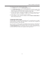
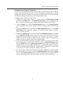
Entering the Menu System ............................................................................................................................... 13
Saving and Exiting ............................................................................................................................................ 14
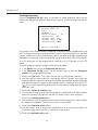
Administrator and Supervisor Menus ............................................................................................................... 14
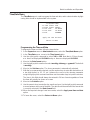
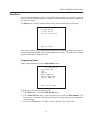
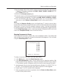
Time/Date Menu ............................................................................................................................................... 15
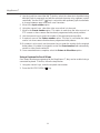
Programming the Time and Date................................................................................................................ 15
DST (Daylight Saving Time)........................................................................................................................ 16
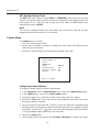
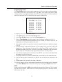
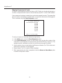
Camera Menu ................................................................................................................................................... 16
Configuring Camera Options ...................................................................................................................... 16
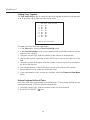
System Menu .................................................................................................................................................... 17
Enabling and Disabling the Program Preset Feature ................................................................................. 17
Changing Pin Numbers............................................................................................................................... 18
Setting Up Partitioning ................................................................................................................................ 19
Configuring Monitor Displays...................................................................................................................... 20
View Menu ........................................................................................................................................................ 21
Programming Views.................................................................................................................................... 21
Using a Keyboard to Recall Views.............................................................................................................. 22
Programming Tours..................................................................................................................................... 23
Linking Tours Together................................................................................................................................ 24
Using a Keyboard to Recall Tours .............................................................................................................. 24
Cancelling a Tour ........................................................................................................................................ 25
Alarm Menu....................................................................................................................................................... 25
Configuring Global Alarm Settings.............................................................................................................. 26
Specifying Alarm Monitors .......................................................................................................................... 28
Configuring Alarm Inputs ............................................................................................................................ 28
Configuring Auxiliary Outputs ..................................................................................................................... 29
Creating Responses ................................................................................................................................... 30
Mapping Responses to Alarms ................................................................................................................... 31

2
MegaPower LT
Mapping Responses to Events ................................................................................................................... 32
Programming an Alarm: A Summary .......................................................................................................... 33
Installer Menu ................................................................................................................................................... 34
Configuring System Options ....................................................................................................................... 34
Assigning Keyboard Priorities..................................................................................................................... 35
Running a Dome Ping................................................................................................................................. 36
Vertical Phase Synchronisation .................................................................................................................. 37
Saving and Restoring Defaults ................................................................................................................... 37
APPENDIX A: FACTORY DEFAULTS ............................................................................................................. 38
APPENDIX B: PASSWORD RECOVERY........................................................................................................ 40
APPENDIX C: SPECIFICATIONS .................................................................................................................... 41
APPENDIX D: ALARMS................................................................................................................................... 42
APPENDIX E: KEYBOARD INSTALLATION ADDENDUM ............................................................................. 43
APPENDIX F: CONNECTION DIAGRAMS ..................................................................................................... 46

3
Matrix Installation and Operation
Chapter 1: Layout and Installation
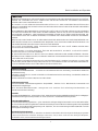
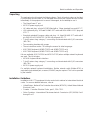
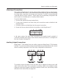
This chapter describes the layout of the MegaPower LT. It also describes the procedure
that should be followed to unpack, mount, connect and install the unit.
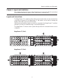
Layout and Connections
The MegaPower LT is a matrix to which video sources and monitor can be connected. By
connecting a keyboard to the MegaPower LT, the matrix can be used to manage the
display of the video sources on the monitors.
Alarm inputs and auxiliary outputs can also be connected to the MegaPower LT, and their
operation can also be controlled using a connected keyboard.
The MegaPower LT stores a menu system through which all connected devices can be
configured.
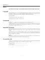
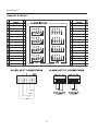
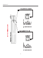
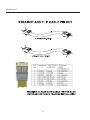
MegaPower LT (16x4)
MegaPower LT (32x8)

4
MegaPower LT
Video Inputs
The 32x8 unit has 32 video input connections. The 16x4 unit has 16 video input connections.
They are BNC loop-through connectors with automatic termination. Each connector is
labelled on the unit.
Video Outputs
The 32x8 unit has 8 video output connections. The 16x4 unit has 4 video output connections.
Connect output connector 1 to monitor 1, output connector 2 to monitor 2, etc. Each
connector is labelled on the unit.
Dome Control
The unit has a connection for RS485 Sensornet dome cameras. Up to 32 dome cameras
can be looped from this connection. See page 7 for more details.
Alarm Inputs
The alarm input connectors are of a plug assembly type. Each plug has one ground
connection and four alarm input connections. The MegaPower LT 32x8 can have up to 32
alarm inputs while the MegaPower LT 16x4 can have up to 16. See page 9 for more
details.
Dip Switches
These dip switches are used for RS485 network and dome camera control biasing and
termination. See page 10 for more details.
Remote Keyboard
The unit can be connected to RS232 and RS485 remote keyboards via a RJ45 connector.
It provides an upload/download function for UTC and matrix devices.
Power Connection
The unit is powered via the supplied UL listed, class 2 LPS 12V DC power supply. Cable
retention is provided.
Auxiliary Outputs
The auxiliary output connector is of a plug assembly type. There are a maximum of two
voltage-free output relays available, providing normally-open and normally-closed contacts
(maximum rating 24V, 2A resistive load). See page 9 for more details.
IMPORTANT NOTE
In the event of power interruption, the MegaPower LT will lose current camera and monitor
selections and revert to its default settings upon reconnection of the supply.
All monitor and camera pairings must be re-entered if required. However, any tours or
views that were active do not need to be re-entered as they will restart.
If this recovery action is not sufficient for the application, it is recommended that the unit
and its associated equipment is supplied from a secure and uninterruptible power supply.

5
Matrix Installation and Operation
Unpacking
The packaging should contain the following items. Check all product codes on the label.
If you have an incorrect item or it is damaged then inform your supplier and the carriers
immediately. If the equipment is incorrect or damaged, do not attempt to use it.
• The MegaPower LT unit
• MP-PSU power supply unit
• UK cable and plug - plug to BS1363 fitted with a 3 Amp standard fuse and IEC C7
• USA cable and plug - UL listed 18 AWG SPT cable with USA NEMA 1-15 P plug and
IEC C7
• Standard mainland European cable and plug - UL listed 18 AWG SPT cable with 2
pin EUROPLUG EN 50075 2.5 A 250 Volt plug and IEC C7
• 7 foot/2 meters long category 5 connecting cord terminated with RJ45 connectors
(MP-CBL)
• Two mounting brackets with screws
• These instructions and a CD holding the manual in other languages
• ADCC0200 keyboard (ADMPLT16C2 and ADMPLT32C2 only)
• ADCC0300 keyboard (ADMPLT16C3 and ADMPLT32C3 only)
Kits are available (ADCCACPSN and ADCCACPSP) when multiple network keyboards
are used. This kit includes:
• MP-KMI Keyboard Matrix Interface
• 7 foot/2 meters long category 5 connecting cord terminated with RJ45 connectors
(MP-CBL)
• MP-PSU power supply unit
For multiple network keyboard installations, Belden network cable (Belden 8761 or
equivalent single twisted pair, screened, 22 AWG) may be required. This is to be provided
by the installer.
Installation Guidelines
Installation of all CCTV equipment is to be carried out to national or international electrical
codes. For a more detailed reference, refer to:
• United States - National Fire Protection Association (NFPA70), United States National
Electrical Code.
• Canada - Canadian Electrical Code, part 1, CSA C22.1.
• Other Countries - International Electromechanical Commission (IEC) 60364, Part 1
through Part 7.

6
MegaPower LT
Mounting the Unit
All models of the MegaPower LT unit are equipped with mounting holes and are supplied
with screws and brackets for the optional fitting to a suitable rack or wall. Should the unit
be mounted, particular attention should be paid to ensure that the specification of the
equipment is not compromised. In particular, airflow, access, power isolation, weight and
any possible contamination should be considered, as should the potential for any abuse
that may lead to an operational malfunction or safety violation.
When choosing a suitable location for the unit, ensure:
• An electrical output socket with overload and short circuit protection is located within
a suitable distance for the included MP-PSU power supply.
• The power supply cord cannot become pinched or trapped under a heavy object.
The power cord should be routed so that it is not likely to be walked on.
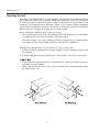
When fixing the MegaPower LT into a either a 19” rack or onto a wall:
1. Fix the mounting brackets with the screws supplied. See the diagrams shown below
for guidance.
2. Screw the bracket mounted MegaPower LT into a either a 19” rack or onto a wall.
• Screws used to fix the MegaPower LT into either a 19” rack or onto a wall must be of
a suitable size and strength.
• When fixing the MegaPower LT onto a wall, the wall must be durable enough to take
the weight of the unit.

7
Matrix Installation and Operation
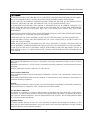
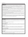
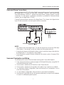
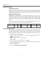
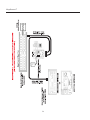
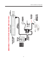
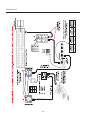
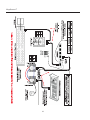
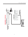
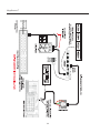
Sensornet Dome Connections
Video inputs that use UTC (AD Up-the-Cable) communication protocol communicate with
the MegaPower LT through the video BNC connection. However, video inputs using
Sensornet telemetry control (i.e., typically Sensornet dome cameras) require a second
connection. For this reason, a telemetry connection is provided for Sensornet dome
cameras (two on MegaPower LT 32x8).
Connect Sensornet dome cameras to the MegaPower LT as shown in the figure below.
Up to 32 data connections can be looped from this connection.
NOTES
• The distance from the MegaPower LT to the last dome must not exceed 3300 feet/
1000 meters. If star wiring is used, this distance will be greatly reduced.
• It may be necessary to terminate the dome control connection using a dip switch on
the MegaPower LT. See page 8 for more details.
• Sensornet dome cameras must be addressed in the menu system. See page 16 for
more details.
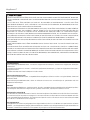
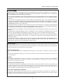
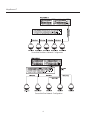
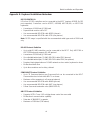
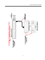
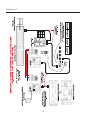
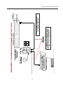
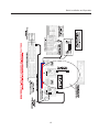
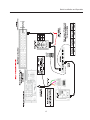
Sensornet Termination and Wiring
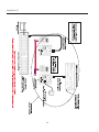
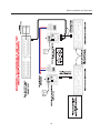
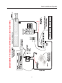
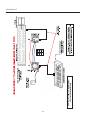
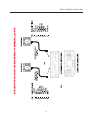
The following rules must be observed when working with a SensorNet network:
1. Each Sensornet link has a maximum length of 3300 feet/1000 meters (using AWG 22
unshielded twisted-pair cable).
2. There can be a maximum of 32 devices in each Sensornet link.
3. There can be a maximum of 4 repeaters in the path of any 2 devices in a network.
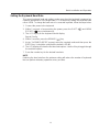
4. In a backbone network configuration, there must always be 2 terminations, one at
each end of the network.
5. In a star network configuration, there must be no more than 4 terminations.
6. Receivers on SensorNet devices will operate satisfactorily at signal levels between
5V and 0.3V (differential peak-to-peak).

8
MegaPower LT
SensorNet Backbone Network Configuration
SensorNet Star Network Configuration

9
Matrix Installation and Operation
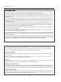
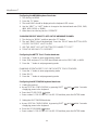
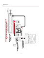
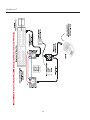
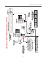
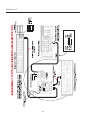
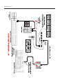
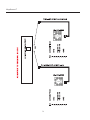
Alarm Input Connections
Each model of MegaPower LT has the same number of alarm inputs as camera inputs.
The alarm inputs are located on removable five way-terminal blocks, with each plug holding
four alarm input connections and one ground connection. The MPLT senses physically
connected alarms (via dry contacts). These inputs can be individually configured in the
menu system as normally-open or normally-closed contacts.
To connect alarm inputs:
1. Remove the required five-way terminal block.
2. Connect each terminal to an alarm relay, with connections made as labelled in the
diagram below:
3. Group the returns and lead them into the ground connection.
4. Return the five-way terminal block to its position on the MegaPower LT.
In the menu system, the alarm input connections are normally-closed by default. If
connecting normally-open alarms, ensure that the alarm input sense is re-configured in
the menu system (see page 34).
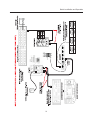
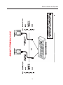
Auxiliary Output Connections
MegaPower LT 16x4 models have one auxiliary output and MegaPower LT 32x8 models
have two. To connect an auxiliary output, remove the three-way terminal block and connect
alarm or auxiliary equipment in one of the relay configurations shown below:
The auxiliary output will operate in the rest state until it is triggered, at which point it will
switch to the active state. Once connected, an auxiliary output can be added to alarm
responses in the menu system so that when an alarm or event occurs, the auxiliary output
will switch to the active state (see page 35).

10
MegaPower LT
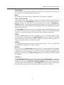
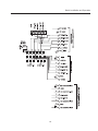
Dip Switch Settings
Keyboard Dip Switches
Keyboard have built in network termination and biasing. For most small to medium sized
installations, it should not be necessary to change the switches from their default settings.
Large installations may require network biasing and/or terminating. Please refer to your
keyboard handbook for details.
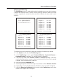
MegaPower LT Dip Switches
The MegaPower LT dip switches are used for RS485 network and dome camera control
biasing and termination. For most small to medium sized installations, it should not be
necessary to change the switches from their default settings. Large installations may
require network biasing and/or terminating. The default setting for all four switches is OFF
(down).
There is one dome control dip switch to be set on the MegaPower LT 16x4, but the user
must set two dome control dip switches on the MegaPower LT 32x8.
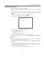
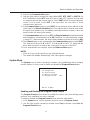
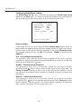
Setting the Keyboard ID
Before a user can program the MegaPower LT using the built-in menu system, the
connected keyboard must be given an ID and the baud rate must be set correctly. Each
keyboard in the system needs to have a unique ID. ID’s are from 1 to 8, with ID 1 having
the highest priority. To change the ID of a connected keyboard, follow the steps below:
1. Connect the power to the keyboard.
2. Within 5 seconds of connecting the power, press the SHIFT (
) and MENU ESCAPE
( ) keys simultaneously.
3. The LCD display on the keyboard will display:
Special Config
4. Within 5 seconds, press the REVERSE PLAY (
) key.
5. At the "Enter keyboard address" prompt, use the number keys to enter the keyboard
address required (default is 1).
6. Press the ENTER key.
7. Move on to Setting the Keyboard Baud Rate.
Network Setting Switch 1 Switch 2 Network Setting Switch 3 Dome Control Switch 4
Biased ON ON Terminated ON Terminated ON
Not Biased OFF OFF Not Terminated OFF Not Terminated OFF

11
Matrix Installation and Operation
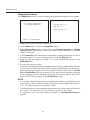
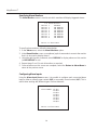
Setting the Keyboard Baud Rate
The current keyboard baud rate setting can be seen when the keyboard is powered up.
Optimum performance of the MegaPower LT is achieved by setting the keyboard baud
rate to 19200. To change the baud rate of a connected keyboard, follow the steps below:
1. Connect the power to the keyboard.
2. Within 5 seconds of reconnecting the power, press the SHIFT (
) and MENU
ESCAPE (
) keys simultaneously.
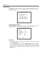
3. The LCD display on the keyboard should display:
Special Config
4. Within 5 seconds, press the REWIND ( ) key.
5. At the "1=RS485 2=RS232" prompt, select the required mode and then press the
ENTER key. It should be noted that the default is RS485.
6. The LCD display will show the first baud rate options. Use the 0 key to toggle through
the available options.
7. Press the number key for the desired baud rate.
NOTE
Reducing the baud rate from the optimum setting will reduce the number of keyboards
that can perform telemetry operations at any one time.

12
MegaPower LT
Chapter 2: The Menu System
The menu system is used to program the MegaPower LT as required using the keyboard.
This chapter give details about how to use the menu system. Menu operation and navigation
is documented for RS485 keyboards. RS232 keyboard functionality may differ.
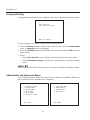
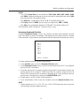
Status Levels
There are three different user status levels, two of which have access to the menu system.
Operator – only operates the system. No menu access allowed.
Supervisor – is able to modify settings within the Supervisor menu.
Administrator/Installer – has access to all menu items.
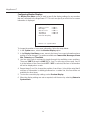
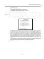
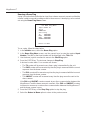
Menu Navigation
A keyboard joystick can be used to navigate the menu system. In general, a menu item is
selected and edited as follows:
1. Use Joystick Up/Down movements to move between menu items. The currently
selected menu item will flash.
2. Use the ENTER key or Joystick Right to select a menu item.
3. In the resulting screen, use:
• The Joystick Up/Down movement to move through the menu items in a screen.
• The Joystick Left/Right to toggle through and select the options for a menu item.
• The numerical keys to input numerical data.
• The SHIFT (
) key held down whilst using Joystick Up/Down movements to
change between capital letters and lower-case.
• The MENU ESCAPE (
) key to return to the previous menu.
NOTES
• When menu items are being edited, automatic functions (e.g. alarms and tours)
cease operating.
• Menus can be displayed on any monitor, however only one monitor can display the
menus at once.
• Any operation calling for the use of the SHIFT (
) key requires this key to be held
down whilst another key is pressed. This is the same way in which the SHIFT key
operates on a PC keyboard.
• When making changes in a screen, use the Joystick Down command to scroll through
the fields, completing each one in turn. Scrolling back up the screen after changes
have been made will cause the changes to be lost.
La pagina si sta caricando...
La pagina si sta caricando...
La pagina si sta caricando...
La pagina si sta caricando...
La pagina si sta caricando...
La pagina si sta caricando...
La pagina si sta caricando...
La pagina si sta caricando...
La pagina si sta caricando...
La pagina si sta caricando...
La pagina si sta caricando...
La pagina si sta caricando...
La pagina si sta caricando...
La pagina si sta caricando...
La pagina si sta caricando...
La pagina si sta caricando...
La pagina si sta caricando...
La pagina si sta caricando...
La pagina si sta caricando...
La pagina si sta caricando...
La pagina si sta caricando...
La pagina si sta caricando...
La pagina si sta caricando...
La pagina si sta caricando...
La pagina si sta caricando...
La pagina si sta caricando...
La pagina si sta caricando...
La pagina si sta caricando...
La pagina si sta caricando...
La pagina si sta caricando...
La pagina si sta caricando...
La pagina si sta caricando...
La pagina si sta caricando...
La pagina si sta caricando...
La pagina si sta caricando...
La pagina si sta caricando...
La pagina si sta caricando...
La pagina si sta caricando...
La pagina si sta caricando...
La pagina si sta caricando...
La pagina si sta caricando...
La pagina si sta caricando...
La pagina si sta caricando...
La pagina si sta caricando...
La pagina si sta caricando...
La pagina si sta caricando...
La pagina si sta caricando...
La pagina si sta caricando...
La pagina si sta caricando...
La pagina si sta caricando...
La pagina si sta caricando...
La pagina si sta caricando...
La pagina si sta caricando...
La pagina si sta caricando...
La pagina si sta caricando...
La pagina si sta caricando...
La pagina si sta caricando...
La pagina si sta caricando...
La pagina si sta caricando...
La pagina si sta caricando...
La pagina si sta caricando...
La pagina si sta caricando...
La pagina si sta caricando...
La pagina si sta caricando...
-
 1
1
-
 2
2
-
 3
3
-
 4
4
-
 5
5
-
 6
6
-
 7
7
-
 8
8
-
 9
9
-
 10
10
-
 11
11
-
 12
12
-
 13
13
-
 14
14
-
 15
15
-
 16
16
-
 17
17
-
 18
18
-
 19
19
-
 20
20
-
 21
21
-
 22
22
-
 23
23
-
 24
24
-
 25
25
-
 26
26
-
 27
27
-
 28
28
-
 29
29
-
 30
30
-
 31
31
-
 32
32
-
 33
33
-
 34
34
-
 35
35
-
 36
36
-
 37
37
-
 38
38
-
 39
39
-
 40
40
-
 41
41
-
 42
42
-
 43
43
-
 44
44
-
 45
45
-
 46
46
-
 47
47
-
 48
48
-
 49
49
-
 50
50
-
 51
51
-
 52
52
-
 53
53
-
 54
54
-
 55
55
-
 56
56
-
 57
57
-
 58
58
-
 59
59
-
 60
60
-
 61
61
-
 62
62
-
 63
63
-
 64
64
-
 65
65
-
 66
66
-
 67
67
-
 68
68
-
 69
69
-
 70
70
-
 71
71
-
 72
72
-
 73
73
-
 74
74
-
 75
75
-
 76
76
-
 77
77
-
 78
78
-
 79
79
-
 80
80
-
 81
81
-
 82
82
-
 83
83
-
 84
84


American Dynamics MegaPower LT specificazione
- Tipo
- specificazione
in altre lingue
Documenti correlati


Altri documenti
-
Videotec SM164A Operating Instructions Manual
-
-
Altronix R2432300ULCB Scheda dati
-
Tyco American Dynamics Illustra 625 Quick Reference Manual
-
AEG CE4400EX Manuale utente
-
-
Yamaha RX-V779 Remote Control Code
-
Yamaha HTR-4065 Remote Control Code
-
Bticino 318015 Istruzioni per l'uso
-