Hangar 9 HAN5260B Manuale del proprietario
- Categoria
- Giocattoli telecomandati
- Tipo
- Manuale del proprietario

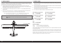
Cub Crafters XCub 60cc
Instruction Manual
Bedienungsanleitung
Manuel d’utilisation
Manuale di Istruzioni
Scan the QR code and select the Manuals and Support quick links from the product
page for the most up-to-date manual information.
Scannen Sie den QR-Code und wählen Sie auf der Produktseite die Quicklinks
Handbücher und Unterstützung, um die aktuellsten Informationen zu Handbücher.
Scannez le code QR et sélectionnez les liens rapides Manuals and Support sur la
page du produit pour obtenir les informations les plus récentes sur le manuel.
Scannerizzare il codice QR e selezionare i Link veloci Manuali e Supporto dalla
pagina del prodotto per le informazioni manuali più aggiornate.
HAN5260
Updated 12/2022

2
NOTICE
All instructions, warranties and other collateral documents are subject to change at the sole discretion of Horizon
Hobby, LLC. For up-to-date product literature, visit horizonhobby.com or www.towerhobbies.com and click on the
support or resources tab for this product.
Age Recommendation: Not For Children Under 14 Years. This Is Not A Toy.
SAFETY WARNINGS AND PRECAUTIONS
Read and follow all instructions and safety precautions before use. Improper use can result in fi re, serious injury and
damage to property.
Components
Use only with compatible components. Should any compatibility questions exist, please refer to the product
instructions, component instructions or contact the appropriate Horizon Hobby offi ce.
Flight
Fly only in open areas to ensure safety. It is recommended fl ying be done at radio control fl ying fi elds. Consult local
ordinances before choosing a fl ying location.
Propeller
Always keep loose items that can become entangled in the propeller away from the prop. This includes loose clothing
or other objects such as pencils and screwdrivers. Keep your hands away from the propeller as injury can occur.
Batteries
Always follow the manufacturer’s instructions when using and disposing of any batteries. Mishandling of Li-Po
batteries can result in fi re causing serious injury and damage.
Small Parts
This kit includes small parts and should not be left unattended near children as choking and serious injury could result.
MEANING OF SPECIAL LANGUAGE
The following terms are used throughout the product literature to indicate various levels of potential harm when
operating this product:
WARNING: Procedures, which if not properly followed, create the probability of property damage, collateral damage,
and serious injury OR create a high probability of superfi cial injury.
CAUTION: Procedures, which if not properly followed, create the probability of physical property damage AND a
possibility of serious injury.
NOTICE: Procedures, which if not properly followed, create a possibility of physical property damage AND a little or
no possibility of injury.
WARNING: Read the ENTIRE instruction manual to become familiar with the features of the product before
operating. Failure to operate the product correctly can result in damage to the product, personal property and
cause serious injury.
This is a sophisticated hobby product. It must be operated with caution and common sense and requires some basic
mechanical ability. Failure to operate this Product in a safe and responsible manner could result in injury or damage
to the product or other property. This product is not intended for use by children without direct adult supervision. Do
not attempt disassembly, use with incompatible components or augment product in any way without the approval
of Horizon Hobby, LLC. This manual contains instructions for safety, operation and maintenance. It is essential to
read and follow all the instructions and warnings in the manual, prior to assembly, setup or use, in order to operate
correctly and avoid damage or serious injury.
SAFE OPERATING RECOMMENDATIONS
• Inspect your model before every fl ight to ensure it is airworthy.
• Be aware of any other radio frequency user who may present an interference problem.
• Always be courteous and respectful of other users in your selected fl ight area.
• Choose an area clear of obstacles and large enough to safely accomodate your fl ying activity.
• Make sure this area is clear of friends and spectators prior to launching your aircraft.
• Be aware of other activities in the vicinity of your fl ight path that could cause potential confl ict.
• Carefully plan your fl ight path prior to launch.
• Abide by any and all established AMA National Model Aircraft Safety Code.
BEFORE STARTING ASSEMBLY
• Remove parts from bag.
• Inspect fuselage, wing panels, rudder and stabilizer for damage.
• If you fi nd damaged or missing parts, contact your place of purchase.
• Charge transmitter and receiver batteries.
• Center trims and sticks on your transmitter.
• For a computer radio, create a model memory for this particular model.
• Bind your transmitter and receiver, using your radio system’s instructions.
NOTICE: Rebind the radio system once all control throws are set. This will keep the servos from moving to their
endpoints until the transmitter and receiver connect. It will also guarantee the servo reversal settings are saved in the
radio system.
IMPORTANT FEDERAL AVIATION ADMINISTRATION (FAA) INFORMATION
Use the QR code to learn more about the Recreational UAS Safety Test (TRUST), as was introduced
by the 2018 FAA Reauthorization Bill. This free test is required by the FAA for all recreational fl yers
in the United States. The completed certifi cate must be presented upon request by any FAA or law
enforcement offi cial.
If your model aircraft weighs more than .55lbs or 250 grams, you are required by the FAA to
register as a recreational fl yer and apply your registration number to the outside of your aircraft.
Use the QR code to learn more about registering with the FAA..
IMAGES WITHIN THE MANUAL
The trim scheme and colors shown in this manual have been updated. Refer to the website product pages for the most
up-to-date information.

3
Cub Crafters XCub 60cc
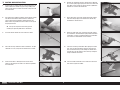
HINWEIS
Alle Anweisungen, Garantien und andere Begleitdokumente können von Horizon Hobby, LLC nach eigenem Ermessen
geändert werden. Um aktuelle Produktinformationen zu erhalten, besuchen Sie horizonhobby.com oder www.
towerhobbies.com und klicken Sie auf die Registerkarte Support oder Ressourcen für dieses Produkt.
Nicht geeignet für Kinder unter 14 Jahren. Dies ist kein Spielzeug.
WARNUNGEN UND SICHERHEITS-VORKEHRUNGEN
Bitte lesen und befolgen Sie alle Anweisungen und Sicherheitsvorkehrungen vor dem Gebrauch. Falscher, nicht
sachgemäßer Gebrauch kann Feuer, ernsthafte Verletzungen und Sachbeschädigungen zur Folge haben.
Komponenten
Verwenden Sie mit dem Produkt nur kompatible Komponenten. Sollten Fragen zur Kompatibilität auftreten, lesen Sie
bitte die Produkt- oder Bedienungsanweisung oder kontaktieren den Service von Horizon Hobby.
Fliegen
Fliegen Sie um Sicherheit garantieren zu können, nur in weiten offenen Gegenden. Wir empfehlen hier den Betrieb auf
zugelassenen Modellfl ugplätzen. Bitte beachten Sie lokale Vorschriften und Gesetze, bevor Sie einen Platz zum Fliegen
wählen.
SPEZIELLE BEDEUTUNGEN
Die folgenden Begriffe werden in der gesamten Produktliteratur verwendet, um auf unterschiedlich hohe
Gefahrenrisiken beim Betrieb dieses Produkts hinzuweisen:
WARNUNG: Wenn diese Verfahren nicht korrekt befolgt werden, ergeben sich wahrscheinlich Sachschäden,
Kollateralschäden und schwere Verletzungen ODER mit hoher Wahrscheinlichkeit oberfl ächliche Verletzungen.
ACHTUNG: Wenn diese Verfahren nicht korrekt befolgt werden, ergeben sich wahrscheinlich Sachschäden UND die
Gefahr von schweren Verletzungen.
HINWEIS: Wenn diese Verfahren nicht korrekt befolgt werden, können sich möglicherweise Sachschäden UND
geringe oder keine Gefahr von Verletzungen ergeben.
WARNUNG: Lesen Sie die GESAMTE Bedienungsanleitung, um sich vor dem Betrieb mit den Produktfunktionen
vertraut zu machen. Wird das Produkt nicht korrekt betrieben, kann dies zu Schäden am Produkt oder persönlichem
Eigentum führen oder schwere Verletzungen verursachen.
Dies ist ein hochentwickeltes Hobby-Produkt. Es muss mit Vorsicht und gesundem Menschenverstand betrieben
werden und benötigt gewisse mechanische Grundfähigkeiten. Wird dieses Produkt nicht auf eine sichere und
verantwortungsvolle Weise betrieben, kann dies zu Verletzungen oder Schäden am Produkt oder anderen Sachwerten
führen. Dieses Produkt eignet sich nicht für die Verwendung durch Kinder ohne direkte Überwachung eines
Erwachsenen. Verwenden Sie das Produkt nicht mit inkompatiblen Komponenten oder verändern es in jedweder Art
ausserhalb der von Horizon Hobby, LLC vorgegebenen Anweisungen. Diese Bedienungsanleitung enthält Anweisungen
für Sicherheit, Betrieb und Wartung. Es ist unbedingt notwendig, vor Zusammenbau, Einrichtung oder Verwendung
alle Anweisungen und Warnhinweise im Handbuch zu lesen und zu befolgen, damit es bestimmungsgemäß betrieben
werden kann und Schäden oder schwere Verletzungen vermieden werden.
Sicherheit der Turbine
Befolgen Sie alle im Handbuch für Ihre spezielle Turbine beschriebenen Sicherheitsvorkehrungen für Turbinen. Weitere
Einzelheiten fi nden Sie auf der Website von AMA. (https://www.modelaircraft.org/system/fi les/documents/510-A.pdf)
Akkus
Folgen Sie immer den Herstelleranweisungen bei dem Gebrauch oder Entsorgung von Akkus. Falsche Behandlung von
LiPo Akkus kann zu Feuer mit Körperverletzungen und Sachbeschädigung führen.
Kleinteile
Dieser Baukasten beinhaltet Kleinteile und darf nicht unbeobachtet in der Nähe von Kindern gelassen werden, da die
Teile verschluckt werden könnten mit ernsthaften Verletzung zur Folge.
EMPFEHLUNGEN ZUM SICHEREN BETRIEB
• Überprüfen Sie zur Flugtauglichkeit ihr Modell vor jedem Flug.
• Beachten Sie andere Piloten deren Sendefrequenzen ihre Frequenz stören könnte.
• Begegnen Sie anderen Piloten in ihrem Fluggebiet immer höfl ich und respektvoll.
• Wählen Sie ein Fluggebiet, dass frei von Hindernissen und groß genug ist.
• Stellen Sie vor dem Start sicher, dass die Fläche frei von Freunden und Zuschauern ist.
• Beobachten Sie den Luftraum und andere Flugzeuge/Objekte die ihren Flugweg kreuzen und zu einem Konfl ikt
führen könnten.
• Planen Sie sorgfältig ihren Flugweg vor dem Start.
VOR DEM ZUSAMMENBAU
• Entnehmen Sie zur Überprüfung jedes Teil der Verpackung.
• Überprüfen Sie den Rumpf, Tragfl ächen, Seiten- und Höhenruder auf Beschädigung.
• Sollten Sie beschädigte oder fehlende Teile feststellen, kontaktieren Sie bitte den Verkäufer.
• Laden des Senders und Empfängers.
• Zentrieren der Trimmungen und Sticks auf dem Sender.
• Sollten Sie einen Computersender verwenden, resetten Sie einen Speicherplatz und benennen ihn nach dem Modell.
• Sender und Empfänger jetzt nach den Bindeanweisung des Herstellers zu binden.
HINWEIS: Das Funksystem nach dem Einstellen der Ruderausschläge erneut binden. Damit wird verhindert, dass sich
die Servos auf ihre Endpunkte bewegen, ehe Sender und Empfänger verbunden sind. Außerdem wird garantiert, dass
die Servo-Umkehreinstellungen im Funksystem gespeichert werden.
BILDER IN DIESEM HANDBUCH
Die in diesem Handbuch dargestellten Trimmungsschemata und Farben wurden überarbeitet. Aktuelle Informationen
fi nden Sie auf den Produktseiten der Internetseite.

4
REMARQUE
Les instructions, garanties et autres documents associés sont soumis à des modifi cations à la seule discrétion
d’HorizonHobby,LLC. Pour obtenir les documents à jour du produit, consultez le site horizonhobby.com ou www.
towerhobbies.com et cliquez sur l’onglet d’aide ou de ressources pour ce produit.
SIGNIFICATION DE CERTAINS TERMES SPÉCIFIQUES
Les termes suivants sont utilisés dans l’ensemble du manuel pour indiquer différents niveaux de danger lors de
l’utilisation de ce produit:
AVERTISSEMENT: Procédures qui, si elles ne sont pas suivies correctement, peuvent entraîner des dégâts matériels
et des blessures graves OU engendrer une probabilité élevée de blessure superfi cielle.
ATTENTION: Procédures qui, si elles ne sont pas suivies correctement, peuvent entraîner des dégâts matériels ET des
blessures graves.
REMARQUE: Procédures qui, si elles ne sont pas suivies correctement, peuvent entraîner des dégâts matériels ET
éventuellement un faible risque de blessures.
AVERTISSEMENT: Lisez la TOTALITÉ du manuel d’utilisation afi n de vous familiariser avec les caractéristiques du
produit avant de le faire fonctionner. Une utilisation incorrecte du produit peut entraîner sa détérioration, ainsi que des
risques de dégâts matériels, voire de blessures graves.
Ceci est un produit de loisirs sophistiqué. Il doit être manipulé avec prudence et bon sens et requiert des aptitudes
de base en mécanique. Toute utilisation irresponsable de ce produit ne respectant pas les principes de sécurité peut
provoquer des blessures, entraîner des dégâts matériels et endommager le produit. Ce produit n’est pas destiné à
être utilisé par des enfants sans la surveillance directe d’un adulte. N’essayez pas de modifi er ou d’utiliser ce produit
avec des composants incompatibles hors des instructions fournies par Horizon Hobby, LLC. Ce manuel comporte des
instructions relatives à la sécurité, au fonctionnement et à l’entretien. Il est capital de lire et de respecter la totalité
des instructions et avertissements du manuel avant l’assemblage, le réglage et l’utilisation, ceci afi n de manipuler
correctement l’appareil et d’éviter tout dégât matériel ou toute blessure grave.
Suivez toujours les instructions du fabricant de vos batteries. Une mauvaise manipulation d’une batterie Li-Po peut
entraîner un incendie causant de graves dégâts matériels et des blessures corporelles.
Petites pièces
Ce kit contient des petites pièces qui ne doivent pas être laissées à la portée des enfants, ces pièces sont dangereuses
pour eux et peuvent entraîner de graves blessures.
CONSIGNES DE SÉCURITÉ CONCERNANT L’UTILISATION
• Inspectez votre modèle avant chaque vol.
• Surveillez les fréquences utilisées à proximité.
• Soyez toujours courtois et respectueux des autres utilisateurs de la zone de vol.
• Choisissez une zone dégagée de tout obstacle et suffi samment grande pour voler en toute sécurité.
• Contrôlez que la zone est libre de spectateurs avant de lancer votre modèle.
• Soyez conscient des autres activités aux alentours de votre vol, risque de confl it potentiel.
• Planifi ez votre vol avant de le commencer.
AVANT DE COMMENCER L’ASSEMBLAGE
• Retirez toutes les pièces des sachets pour les inspecter.
• Inspectez soigneusement le fuselage, les ailes et les empennages.
• Si un élément est endommagé, contactez votre revendeur.
• ll est recommandé de préparer tous les éléments du système de la radio.
• Cela inclut la charge des batteries comme la mise au neutre des trims et des manches de votre émetteur.
• Si vous utilisez une radio programmable, sélectionnez une mémoire libre afi n d’y enregistrer les paramètres de ce
modèle.
• Nous vous recommandons d’affecter maintenant le récepteur à l’émetteur en suivant les instructions fournies avec
votre radio.
REMARQUE: Reconnectez le système radio une fois que tous les coudes de contrôle sont confi gurés. Cette action
empêche les servos de se déplacer vers leurs extrémités jusqu’à la connexion de l’émetteur et du récepteur. Cela
garantit aussi que les paramètres d’inversion du servo sont enregistrés dans le système radio.
IMAGES À L’INTÉRIEUR DU MANUEL
Le motif et les couleurs montrés dans le manuel ont été modernisés. Veuillez vous référer aux pages des produits sur
le site Internet pour consulter les informations les plus récentes.
14 ans et plus. Ceci n’est pas un jouet.
AVERTISSEMENTS RELATIFS À LA SÉCURITÉ
Lisez et suivez toutes les instructions relatives à la sécurité avant utilisation. Une utilisation inappropriée peut entraîner
un incendie, de graves blessures et des dégâts matériels.
Composants
Utilisez uniquement des composants compatibles. Si vous avez des questions concernant la compatibilité, référez-vous
à ce manuel ou contactez le service technique Horizon Hobby.
Le vol
Volez uniquement dans des zones dégagées pour un maximum de sécurité. Il est recommandé d’utiliser les pistes des
clubs d’aéromodélisme. Consultez votre mairie pour connaître les sites autorisés.
Sécurité relative à la turbine
Suivez toutes les procédures de sécurité relatives à la turbine, telles que décrites dans le manuel de votre modèle de
turbine. Vous trouverez de plus amples informations sur le site web de l’AMA. (https://www.modelaircraft.org/system/
fi les/documents/510-A.pdf)
Les batteries

5
Cub Crafters XCub 60cc
AVVISO
Tutte le istruzioni, garanzie e altri documenti collaterali sono soggetti a modifi ca a esclusiva discrezione di Horizon
Hobby, LLC. Per la documentazione aggiornata del prodotto, visitare horizonhobby.com oppure www.towerhobbies.
com e cliccare sulla scheda relativa all’assistenza o alle risorse per il relativo prodotto.
MINIMO 14 anni. Non è un giocattolo.
AVVERTIMENTI E PRECAUZIONI PER LA SICUREZZA
Prima dell’uso leggere attentamente tutte le istruzioni e le precauzioni per la sicurezza. In caso contrario si potrebbero
procurare incendi, danni o ferite.
Componenti
Usare solo componenti compatibili. Se ci fossero dubbi riguardo alla compatibilità, è opportuno far riferimento alle
istruzioni relative al prodotto o ai componenti oppure rivolgersi al reparto Horizon Hobby di competenza.
Volo
Per sicurezza volare solo in aree molto ampie. Meglio se in campi volo autorizzati per modellismo. Consultare le
ordinanze locali prima di scegliere luogo dove volare.
Sicurezza della turbina
Seguire le procedure di sicurezza della turbina come indicato nel manuale della turbina. Ulteriori dettagli sono
disponibili sul sito web dell’AMA. (https://www.modelaircraft.org/system/fi les/documents/510-A.pdf)
Batterie
Quando si maneggiano o si utilizzano le batterie, bisogna attenersi alle istruzioni del costruttore; il rischio è di procurare
incendi, specialmente con le batterie LiPo, con danni e ferite serie.
Piccole parti
Questo kit comprende delle parti di piccole dimensioni e non lo si può lasciare incustodito se c’è la presenza di bambini
SIGNIFICATO DEI TERMINI PARTICOLARI
In tutta la documentazione relativa al prodotto sono utilizzati iseguenti termini per indicare vari livelli di potenziale
pericolo durante il funzionamento:
AVVERTENZA: Procedure che, se non debitamente seguite, espongono alla possibilità di danni alla proprietà fi sica
opossono omportare un’elevata possibilità di provocare ferite superfi ciali. Ulteriori precauzioni per la sicurezza e
avvertenze.
ATTENZIONE: Procedure che, se non sono seguite correttamente, possono creare danni materiali E possibili gravi
lesioni.
AVVISO: Procedure che, se non sono seguite correttamente, possono creare danni materiali E nessuna oscarsa
possibilità di lesioni.
AVVERTENZA: Leggere TUTTO il manuale di istruzioni e prendere familiarità con le caratteristiche del prodotto, prima
di farlo funzionare. Un utilizzo scorretto del prodotto può causare danni al prodotto stesso, alle persone oalle cose,
provocando gravi lesioni.
Questo è un prodotto di hobbistica sofi sticato e NON un giocattolo. È necessario farlo funzionare con cautela e
responsabilità e avere conoscenze basilari di meccanica. Se questo prodotto non è utilizzato in maniera sicura e
responsabile potrebbero verifi carsi lesioni odanni al prodotto stesso oad altre proprietà. Non è un prodotto adatto
aessere utilizzato dai bambini senza la diretta supervisione di un adulto. Non usare componenti non compatibili
o alterare il prodotto in nessuna maniera al di fuori delle istruzioni fornite da Horizon Hobby, LLC. Questo manuale
contiene le istruzioni per un funzionamento e una manutenzione sicuri. È fondamentale leggere e seguire tutte le
istruzioni e le avvertenze del manuale prima di montare, confi gurare ofar funzionare il Prodotto, al fi ne di utilizzarlo
correttamente e di evitare danni olesioni gravi.
che li possono inghiottire e rimanere soffocati o intossicati.
RACCOMANDAZIONI PER OPERARE IN SICUREZZA
• Controllare attentamente il modello prima di ogni volo per accertarsi che sia idoneo.
• Essere consapevoli che un altro utente della frequenza in uso, potrebbe procurare delle interferenze.
• Essere sempre cortesi e rispettosi nei confronti degli altri utilizzatori dell’area in cui ci si trova.
• Scegliere un’area libera da ostacoli e abbastanza ampia da permettere lo svolgimento del volo in sicurezza.
• Prima del volo verifi care che l’area sia libera da amici e spettatori.
• Stare attenti alle altre attività che si svolgono in vicinanza della vostra traiettoria di volo, per evitare possibili confl itti.
• Pianifi care attentamente il volo prima di lanciare il modello.
• Rispettare sempre scrupolosamente le regole stabilite dall’associazione locale.
PRIMA DI INIZIARE IL MONTAGGIO
• Togliere tutti i pezzi dalla scatola.
• Verifi care che la fusoliera, l’ala e i piani di coda non siano danneggiati.
• Se si trovano parti danneggiate, contattare il negozio da cui è stato acquistato.
• Caricare il trasmettitore e la batteria di volo.
• Centrare stick e trim sul trasmettitore.
• Con una radio computerizzata creare una nuova memoria per questo modello.
• Facendo riferimento alle istruzioni del radiocomando, connettere (bind) trasmettitore e ricevitore.
AVVISO: una volta impostate tutte le corse dei comandi, effettuare nuovamente la connessione del radiocomando.
Ciò impedirà che i servocomandi si spostino verso i propri fi ne corsa prima del collegamento della trasmittente con il
ricevitore. Ciò inoltre farà in modo che le impostazioni di inversione dei servocomandi siano salvate nel radiocomando.
IMMAGINI ALL’INTERNO DEL MANUALE
Lo schema cromatico e i colori illustrati nel presente manuale sono stati aggiornati. Per informazioni più aggiornate,
consultare le pagine prodotto del sito web.

6
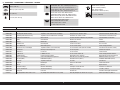
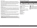
Part # English Deutsch Français Italiano
REPLACEMENT PARTS • ERSATZTEILE • PIÈCES DE RECHANGE • PEZZI DI RICAMBIO
HAN526001 Fuselage Rumpf Fuselage Fusoliera
HAN526002 Left Wing with Aileron and Flap Tragfl äche Links mit Querruder und Klappe Aile gauche avec aileron et volet Semiala sinistra con alettone e fl ap
HAN526003 Right Wing with Aileron and Flap Tragfl äche Rechts mit Querruder und Klappe Aile droite avec aileron et volet Semiala destra con alettone e fl ap
HAN526004 Stabilizer and Elevator Set Höhenruderset Set Plan horizontal et Gouverne de profondeur Set stabilizzatore ed elevatore
HAN526005 Rudder Seitenleitwerk Gouverne de direction Timone
HAN526006 Cowling Motorhaube Capot moteur Carenatura
HAN526007 Hardware Pack Kleinteilepaket Sachet d’accessoires Viti e accessori
HAN526008 Engine Mount Set Motor-Montagesatz Jeu de renfort moteur Set di montaggio motore
HAN526009 Wing Struts Set (Left and Right) Tragfl ächenstreben (Links und Rechts) Jeu d’entretoises d’aile (Gauche et Droite) Set montanti ala (destro e sinistro)
HAN526010 Pushrod Set Gestänge / Anlenkungen Set Jeu de tringleries Set dell’asta di spinta
HAN526011 Window Set Fenster Set Jeu de fenêtres Set fi nestrature
HAN526012 EP Mount Set E-Motorhalter Set Jeu de renforts moteur EP Set di montaggio motore elettrico
HAN526013 Aerotow Release Flugzeugschlepp-Freigabe Dégagement de la remorque Dispositivo di sgancio dell’aerotraino
HAN526014 Super Scale Tailwheel Super-maßstabsgetreues Spornrad Roue de queue à échelle de précision Ruotino di coda in super scala
HAN526016 Gas Tank (20oz) Kraftstofftank (591cc) Réservoir essence (591cc) Serbatoio combustibile (591cc)
HAN526018 Wing Tube Tragfl ächenverbinder Clé d’aile Tubo dell’ala
HAN526019 Decal Set Dekorbogen Planche de décoration Set di decalcomanie
HAN526020 Spinner Spinner Cône Ogiva dell’elica
HAN526021 Fiberglass Fairings Glasfaser-Verkleidung Carénages en fi bre de verre Carenature in vetroresina
HAN526023 2x Seats and Antenna 2X Sitze und Antenne 2x sièges et antenne 2x sedili e antenna
HAN526024 Sprung U/C Feder U/C Ressorts U/C Carrello di atterraggio ammortizzato
SUL887S Sky Airfl ight Wheel with Treads 7-inch Sky Airfl ight Rad mit Gewinde 18cm (7 Zoll) Roue SkyAirfl ight avec bandes 18cm (7po) Ruota Sky Airfl ight con fi letti 7’’
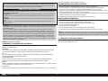
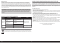
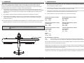
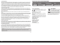
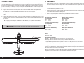
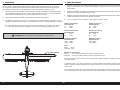
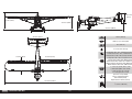
116.0 in (294 cm)
1908 sq in (123.1 dm2) Total
82 in (208 cm)
27–31 lbs (12.0–14.5 kg)
SPECIFICATIONS • SPEZIFIKATIONEN • SPÉCIFICATIONS • SPECIFICHE
2-Stroke Gas: 50cc–70cc, 4-Stroke gas/petrol: 61cc
2-Takt Benziner: 50cc–70cc, 4-Takt Benzin: 61 cc
2 temps Essence: 50cc–70cc, 4 temps essence: 61cc
2-Tempi Gas: 50cc–70cc, 4 tempi benzina: 61 cc
Electric Power: Power 360, 180Kv Brushless
Elektro Antrieb Power: Power 360, 180Kv Brushless
Moteur électrique (EP): Power 360, 180Kv Brushless
Motore elettrico: Power 360, 180Kv Brushless
5-channel (or greater) with 5 servos
5-Kanal (oder größer) mit 5-Servos
5 voies (ou plus) avec 5 servos
a 5 canali (o più) con 5 servo
Spinner: 4-inch (Included)
Spinner: 102mm (Enthalten)
Cône: 102mm (Fourni)
Ogiva dell’elica: 102mm (Inclusa)
71/2 inches (190.5mm)

7
Cub Crafters XCub 60cc
Part # English Deutsch Français Italiano
2-STROKE GAS • 2-TAKT BENZINER • 2 TEMPS ESSENCE • 2-TEMPI A BENZINA
1 DLEG0455 DLE-55RA Rear Exhaust Gas Engine w/ DLE-55RA Abgasmotor mit Heckauspuff und
Schalldämpfer
Moteur à échappement des gaz arrière avec silencieux
DLE-55RA
DLE-55RA motore a benzina con scarico
posteriore e silenziatore
1 DUB671 Super Strength Long Servo Arm: JR Hochfester langer Servoarm: JR Long bras de servo robuste: JR Braccio servo lungo ultra resistente: JR
1 DUB800 Tygon® Gas Tubing, 3’ Large Tygon® Gasleitung, 91cm (3 Fuß) groß Tubulure de gaz Tygon®, large, 91 cm (3pi) Tubi per combustibile Tygon®, diametro 3’
1 HAN116 Fuel Filler with “T” and Overfl ow Fitting Hangar 9 Tanknippel mit T Stück u. Überlauf Fitting Point de remplissage de carburant avec coupleur en T Bocchettone di riempimento carburante con
2 HAN9151 Aluminum Sx Arm, 1 inch SPM JR Aluminium Sx Arm, 25,4mm (1 Zoll) SPM JR Bras Sx en aluminium, JP SPM 25,4mm (1po) Braccio alluminio sx, 1’’, SPM JR
1 SPMA112 3 Wire Ignition/RX Switch 3-Draht-Zündungs-/RX-Schalter Commutateur de récepteur/allumage à 3 fi ls Interruttore 3 fi li accensione/RX
1 SPMA3002 Heavy-Duty Servo Extension 9-inch Servokabelverlängerung 230 mm (9 inch) Rallonge de servo, 230 mm Estensione servo 9 pollici
2 SPMA3005 Heavy-Duty Servo Extension 24-inch Servokabelverlängerung 600 mm (24 inch) Rallonge de servo, 600 mm Estensione servo 24 pollici
4 SPMA3006 Heavy-Duty Servo Extension 36-inch Servokabelverlängerung 920 mm (36 inch) Rallonge de servo, 920 mm Estensione servo 36 pollici
1 SPMA3054 Servo Connector Clips (25) Servosteckerklemmen (25) Attaches de connexion du servo (25) Morsetti servocomando (25)
SPMAR10400T AR10400T 10CH PowerSafe Telemetry
Receiver
PowerSafe-Telemetrieempfänger AR10400T mit 10
Kanälen
Récepteur PowerSafe avec télémétrie AR10400T 10
canaux
Ricevitore di telemetria PowerSafe AR10400T a
10 canali
3 SPMB4000LPRX 4000mAh 2S 7.4V LiPo Receiver Battery LiPo-Empfängerakku (7,4 V / 4000 mAh) Batterie Li-Po de récepteur 7,4 V 4000 mAh Batteria per ricevitore da 7,4 V Li-Po, 4.000 mAh
7 SPMSA6320 A6320 H-T/H-S BrushlessHV Servo A6320 H-T/H-S bürstenloser HV-Servo Servo A6320 H-T/H-S BrushlessHV Servo brushless HV H-T/H-S A6320
1 SPMSA6330 A6330 H-T/H-S Metal Gear HV Serv A6330 H-T/H-S Metallgetriebe HV Serv Servo haute tension à engrenage métallique H-T/H-S
A6330 Servo HV ingranaggi metallo H-T/H-S A6330
ELECTRIC POWER • ELEKTROANTRIEB • MOTEUR ELECTRIQUE (EP) • MOTORE ELETTRICO
1 DUB671 Super Strength Long Servo Arm: JR Hochfester langer Servoarm: JR Long bras de servo robuste: JR Braccio servo lungo ultra resistente: JR
1 EFLM4360A Power 360 BL Outrunner Motor,180Kv Power 360 bürstenloser Außenläufer-Motor,180Kv Moteur à cage tournante sans balais Power 360, 180K Motore outrunner BL Power 360,180K
2 HAN9151 Aluminum Sx Arm, 1 inch SPM JR Aluminium Sx Arm, 25,4mm (1 Zoll) SPM JR Bras Sx en aluminium, JP SPM 25,4mm (1po) Braccio alluminio sx, 1’’, SPM JR
2 SPMA3005 Heavy-Duty Servo Extension 24-inch Servokabelverlängerung 600 mm (24 inch) Rallonge de servo, 600 mm Estensione servo 24 pollici
4 SPMA3006 Heavy-Duty Servo Extension 36-inch Servokabelverlängerung 920 mm (36 inch) Rallonge de servo, 920 mm Estensione servo 36 pollici
1 SPMA3054 Servo Connector Clips (25) Servosteckerklemmen (25) Attaches de connexion du servo (25) Morsetti servocomando (25)
1 SPMAR10400T AR10400T 10CH PowerSafe Telemetry
Receiver
PowerSafe-Telemetrieempfänger AR10400T mit 10
Kanälen
Récepteur PowerSafe avec télémétrie AR10400T 10
canaux
Ricevitore di telemetria PowerSafe AR10400T a
10 canali
2 SPMB4000LPRX 4000mAh 2S 7.4V LiPo Receiver Battery LiPo-Empfängerakku (7,4 V / 4000 mAh) Batterie Li-Po de récepteur 7,4 V 4000 mAh Batteria per ricevitore da 7,4 V Li-Po, 4.000 mAh
7 SPMSA6320 A6320 H-T/H-S BrushlessHV Servo A6320 H-T/H-S bürstenloser HV-Servo Servo A6320 H-T/H-S BrushlessHV Servo brushless HV H-T/H-S A6320
2 SPMX50006S30 5000mAh 6S 22.2V Smart 30C; IC5 5000 mAh 6S 22,2 V Smart 30C; IC5 5000 mAh 6S 22,2 V Smart 30 C ; IC5 5000 mah 6S 22,2 V Smart 30C; IC5
1 SPMXAE1120HV Avian 120A Brushless Smart ESC 12S Avian 120A bürstenloser Smart ESC 12S Variateur ESC sans balais 120 A Smart Avian 12S Smart ESC Avian 120 A Brushless 12S
1 SPMXCA506 Adapter: IC5 Battery/Series 4-inch Adapter: IC5 Akku/Serie 4-inch Adaptateur : batterie IC5/série 10,2 cm (4 po) Adattatore: Batteria IC5/In serie 4”
REQUIRED ADHESIVES • ERFORDERLICHE KLEBSTOFFE • TYPES DE COLLES • ADESIVI NECESSARI
DLMAD44 Roket Rapid CA 5-10 sec: 20g Roket Rapid CA 5-10 s: 20g Colle cyano Roket Rapid 5-10 sec: 20g Colla cianoacrilica Roket Rapid 5-10 sec: 20 g
DLMAD45 Roket Max CA 10-20 sec: 20g Roket Max CA 10-20 s: 20g Colle cyano Roket Max 10-20 sec: 20g Colla cianoacrilica Roket Max 10-20 sec: 20 g
PAAPT715 CA Accelerator Sekundenkleber (CA) Aktivator Accélérateur de colle CA Accelerante colla CA
PAAPT37 5-Minute Epoxy 5 Minuten Epoxy Époxy 5 minutes Colla epossidica 5 minuti

8
Part # English Deutsch Français Italiano
PAAPT35 15-Minute Epoxy 15 Minuten Epoxy Époxy 15 minutes Colla epossidica 15 minuti
PAAPT39 30-Minute Epoxy 30 Minuten Epoxy Époxy 30 minutes Colla epossidica 30 minuti
PAAPT42 Threadlock Schraubensicherungslack Frein-fi let Frenafi letti
DLMAD12 R/C Modeller Canopy Glue: 4 oz R/C Modeller Kanzelkleber: 113,4g (4 oz) Colle à verrière R/C Modeller: 113g Colla per capottine R/C Modeller: 4 oz
REQUIRED TOOLS • BENÖTIGTES WERKZEUG • OUTILS REQUIS • ATTREZZI NECESSARI
Box wrench: 12mm, 1/2-inch Ringschlüssel: 12mm, 1/2-inch Clé hexagonales: 12mm, 1/2-inch Chiavi: 12mm, 1/2-inch
Drill Bohrer Mini-perceuse Trapano
Drill bits: 5/64-inch, 3/32-inch, 7/64-inch,
1/8-inch, 9/64-inch, 3/16-inch Bohrer: 1,5 mm, 2mm, 2,5mm, 3mm, 3,5mm, 5mm Forêt : 1,5 mm, 2mm, 2,5mm, 3mm, 3,5mm, 5mm Punte per trapano: 1,5 mm, 2mm, 2,5mm, 3mm,
3,5mm, 5mm
Epoxy brush Pinsel Pinceau Epoxy Spazzole epoxy
Felt-tipped pen Faserstift Feutre fi n effaçable Pennarello
Flat blade screwdriver, small and large Schraubendreher fl ach Tournevis plat, petit et grand Cacciavite a lama piatta: piccolo, grande
Flat fi le Flachfeile Lime plate Lima piatta
Hemostats Klemme Pince Hemostat Pinzetta
Hex wrench: 1.5mm, 2mm, 2.5mm, 3mm,
4mm, 5mm, 6mm, 3/32-inch
Inbusschlüssel: 1,5mm, 2mm, 2.5mm, 3mm, 4mm,
5mm, 6mm, 3/32-inch
Tournevis hexagonal : 1,5mm, 2mm, 2.5mm, 3mm,
4mm, 5mm, 6mm, 3/32-inch
Chiave esag.: 1,5mm, 2mm, 2.5mm, 3mm,
4mm, 5mm, 6mm, 3/32-inch
Hobby knife with #11 blade Hobbymesser mit # 11 Klinge Couteau : Lame numéro 11 Taglierino: #11 lama
Hobby scissors Hobbyschere Ciseaux Forbici per hobby
Hook and loop strap and tape Klettband Bande auto aggripante Nastro e fascette
Isopropyl alcohol Isopropyl Alkohol Alcool isopropylique Alcol isopropilico
Low-tack tape Kreppband Adhésif de masquage Nastro a bassa aderenza
Mixing cups and sticks Mischbecher und Rührstäbchen Récipients pour mélanger et bâtons Contenitori e stick per mixer colla
Needle nose pliers Spitzzange Pince fi ne Pinze a becco stretto
Nut driver: 5mm, 5.5mm, 10mm, 1/4-inch Steckschlüssel. 5mm, 5.5mm, 10mm, 1/4-inch Clés à douilles : 5mm, 5.5mm, 10mm, 1/4-inch Chiave per dadi: 5mm, 5.5mm, 10mm, 1/4-inch
Paper towels Papiertücher Papier absorbant Asciugamani di carta
Pencil Stift Crayon à papier Matita
Phillips screwdriver: #1, #2 Phillips Schraubendreher: #1,#2 Tournevis cruciforme: #1, #2 Cacciavite a croce: #1, #2
Pin vise Handbohrer Porte forets Trapano manuale
Ruler Lineal Réglet Righello
Sandpaper, medium grit Schleifpapier Papier de verre Carta vetrata
Scissors Schere Ciseaux Forbici
Side cutters Seitenschneider Pince coupante Lama laterale
OPTIONAL ITEMS • OPTIONALE TEILE • ÉLÉMENTS OPTIONNELS • ARTICOLI OPZIONALI
1 HAN526017 Landing Gear Fahrwerk Set Train d’atterrissage Set del carrello di atterraggio
1 SPMA100 Optical Ignition Kill Switch Optischer Zünd-Notausschalter Coupe-circuit optique d’allumage Sezionatore ottico accensione
1 WGT111 Extreme Big Tote,82 x 24 x 3 inches, Red &
Black
Extreme Big Tote, 208 x 60 x 7cm (82 x 24 x 3 Zoll), rot
und schwarz
Grand sac Extrême, 210 x 60 x 10 cm (82 x 24 x 3po),
rouge et noir
Borsa tote Extreme grande, 82 x 24 x 3’’, rossa
e nera

9
Cub Crafters XCub 60cc
OPTIONAL SCALE ACCESSORIES
We have worked with various vendors to develop scale
details specifi cally for this model. These items include
pilot fi gures, decals, propellers, wheels and shocks.
Pilots:
www.tailoredpilots.com
www.warbirdpilots.com
Scale instrument panels:
www.ifl ytailies.com
Custom markings and decals:
www.callie-graphics.com
Scale Propellers:
www.aircraftinternational.com
OPTIONALES MASSSTABSGETREUES
ZUBEHÖR
Wir haben mit verschiedenen Anbietern
zusammengearbeitet, um maßstabsgetreue Einzelteile
speziell für dieses Modell zu entwickeln. Zu diesen
Einzelteilen zählen Pilotenfi guren, Decals, Propeller, Räder
und Stoßdämpfer.
Piloten:
www.tailoredpilots.com
www.warbirdpilots.com
Maßstabsgetreue Instrumententafeln:
www.ifl ytailies.com
Kundenspezi sche Markierungen und Decals:
www.callie-graphics.com
Maßstabgetreue Propeller:
www.aircraftinternational.com
ACCESSOIRES À ÉCHELLE FACULTATIFS
Nous avons collaboré avec plusieurs fournisseurs pour
développer des détails à échelle spécifi quement pour
ce modèle. Notamment des fi gurines de pilote, des
autocollants, des hélices, des roues et des amortisseurs.
Pilotes:
www.tailoredpilots.com
www.warbirdpilots.com
Panneaux d’instrument à échelle:
www.ifl ytailies.com
Marquages et autocollants personnalisés:
www.callie-graphics.com
Hélices à échelle:
www.aircraftinternational.com
ACCESSORI IN SCALA OPZIONALI
Abbiamo collaborato con diversi fornitori per sviluppare
dettagli in scala pensati appositamente per questo
modello. Gli articoli includono piloti in miniatura,
decalcomanie, eliche, ruotini e ammortizzatori.
Piloti:
www.tailoredpilots.com
www.warbirdpilots.com
Pannelli degli strumenti in scala:
www.ifl ytailies.com
Contrassegni e decalcomanie personalizzati:
www.callie-graphics.com
Eliche in scala:
www.aircraftinternational.com

10
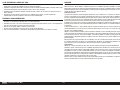
REMOVING WRINKLES
The covering of your model may develop wrinkles during
shipping and will require the use of a heat gun (HAN100)
and covering glove (HAN150) or covering iron (HAN101)
with a sealing iron sock (HAN141) to remove them. Use
caution while working around areas where the colors
overlap to prevent separating the colors. Avoid using
too much heat, which could separate the colors. Placing
a cool damp cloth on adjacent colors will also help in
preventing the separation of the colors while removing
wrinkles.
TRANSPORTATION AND STORAGE
When transporting and storing your model, you will
need a minimum of 82 inches (2.1m) in length, and 24
inches (61cm) in height to accommodate the size of
the fuselage. The width of the stabilizer must also be
taken into consideration, which is 36 inches (9.2cm).
We also recommend the use of a wing bag (WGT111)
to help protect the wings during transport and storage.
The control horns and linkages can also cause damage
to nearby surfaces even when placed in storage bags.
Always place surfaces so the tops are together to prevent
damage from the control horns and linkages.
NOSE WEIGHT
Your model may require the addition of nose weight to
properly balance. Our test aircraft with the recommended
Evolution® 62cc engine and muffl er, and batteries on
either side of the fuel tank required 11/2 lbs (680g) of
nose weight. This may vary from plane to plane. Add
this weight as far forward in the fuselage as possible to
reduce the amount required to balance. This weight must
be secure so it does not come loose in fl ight, causing
an unsafe model which could result in the loss of the
aircraft.
REPLACEMENT COVERING
Your model is covered with UltraCote® fi lm in the
following colors. If repairs are required, order these
coverings to make those repairs.
Silver HANU881
Deep Blue HANU873
Black HANU874
ENTFERNEN VON FALTEN
Während des Transportes können bei der Bespannung
Falten aufgetreten sein. Sie können diese mit dem
Heißluftfön (HAN100) und Bespannhandschuh (HAN150)
oder dem Bügeleisenbezug (HAN141) entfernen. Bitte
achten Sie bei überlappenden Farben diese nicht durch
zuviel Hitze zu lösen. Ein kühlendes Stück Stoff kann hier
neben den Falten aufgelegt helfen, dass die Farben sich
nicht trennen.
TRANSPORT UND LAGERUNG
Beim Transport und der Lagerung des Modells müssen
mindestens 2,1m (82 Zoll) in der Länge und 61cm
(24 Zoll) in der Höhe vorhanden sein, um die Größe
des Rumpfs aufnehmen zu können. Die Breite des
Stabilisators muss ebenfalls beachtet werden, die
9,2cm (36 Zoll) beträgt. Wir empfehlen außerdem die
Verwendung einer Flügeltasche (WGT111), um die
Tragfl ächen bei Transport und Lagerung zu schützen. Die
Steuerhörner und Gestänge können zudem Schäden an
benachbarten Oberfl ächen verursachen, auch wenn sie
in Taschen gelagert sind. Oberfl ächen stets so platzieren,
dass die Oberseiten aneinander liegen, um Schäden
durch Steuerhörner und Gestänge zu vermeiden.
BUGGEWICHT
Das Modell kann für das korrekte Gleichgewicht
ein zusätzliches Buggewicht benötigen. Unser
Testfl ugzeug mit dem empfohlenen Evolution® 62cm³
Motor und Schalldämpfer sowie auf beiden Seiten
des Kraftstofftanks montierten Akkus benötigte ein
Buggewicht von 680g (11/2 lbs). Dies kann von Flugzeug
zu Flugzeug unterschiedlich sein. Dieses Gewicht so weit
vorne im Rumpf wie möglich hinzufügen, um die für das
Gleichgewicht benötigte Menge zu reduzieren. Dieses
Gewicht muss gesichert werden, damit es sich im Flug
nicht löst, wodurch das Modell unsicher wird und zum
Verlust des Flugzeugs führt.
ERSATZABDECKUNG
Die nachfolgenden Abdeckungen werden während der
Montage des Modells verwendet. Sind Reparaturen
erforderlich, die nachfolgenden Abdeckungen zur
Durchführung dieser Reparaturen bestellen.
Silber HANU881
Dunkelblau HANU873
Schwarz HANU874
ÉLIMINATION DES PLIS
L’entoilage de votre modèle peut développer des plis
lors de l’expédition. Vous pouvez les lisser en utilisant le
pistolet à air chaud (HAN100) et le gant (HAN150) ou le
fer à entoiler (HAN101) avec la chaussette de protection
(HAN141). Soyez vigilant sur les zones où plusieurs
couleurs d’entoilage sont superposées, une température
trop élevée pourrait séparer les couleurs. Placez un
chiffon humide et froid sur les couleurs adjacentes pour
éviter leur séparation lorsque vous enlevez les plis.
TRANSPORT ET STOCKAGE
Lorsque vous transportez et stockez votre modèle, vous
devez avoir au minimum un espace de 2,1m (82po) de
longueur et 61cm (24po) de hauteur pour la taille du
fuselage. La largeur du stabilisateur doit également être
prise en compte: 9,2cm (36po). Nous vous conseillons
également d’utiliser un sac à ailes (WGT111) pour
protéger les ailes lors du transport et du stockage. Les
renvois de commande et tringleries peuvent également
endommager les surfaces proches même si rangés dans
des sacs de rangement. Placez toujours ces surfaces
de manière à ce que les sommets soient ensemble
pour prévenir tout dommage causé par les renvois de
commande et les tringleries.
POIDS DU NEZ
Votre modèle peut nécessiter l’ajout d’un poids du nez
à des fi ns d’équilibre. Notre appareil test avec le moteur
recommandé Evolution® 62cc et silencieux, avec
batterie de chaque côté du réservoir de carburant a
nécessité un poids du nez de 680g (11/2lb). Cela peut
varier d’un avion à l’autre. Ajoutez ce poids aussi loin que
possible dans le fuselage pour réduire la quantité requise
pour équilibrer. Ce poids doit être fi xé afi n de ne pas se
desserrer en vol, faute de quoi le modèle ne sera pas
sécuritaire pouvant provoquer la perte de l’appareil.
ENTOILAGE DE RECHANGE
Les entoilages suivants sont utilisés pendant le montage
de votre modèle. Si des réparations sont nécessaires,
commandez les entoilages suivants pour pouvoir
effectuer ces réparations.
Argent HANU881
Bleu foncé HANU873
Noir HANU874
TOGLIERE LE GRINZE
rivestimento di questo modello potrebbe sviluppare delle
grinze durante la spedizione e quindi per toglierle, sarà
necessario usare una pistola termica (phon) (HAN100) e
un guanto speciale (HAN150), oppure un ferro apposito
per rivestimenti (HAN101) con la sua calza (HAN141).
Bisogna usare cautela quando si lavora intorno ad
aeree con sovrapposizione di colori per evitare la loro
separazione. Evitare di scaldare troppo per non separare
i colori. Mettere un panno umido fresco sui colori vicini,
aiuta a prevenire la separazione dei colori mentre si
tolgono le grinze.
TRASPORTO E IMMAGAZZINAGGIO
Durante il trasporto e l’immagazzinaggio del modello,
è necessario uno spazio di almeno 2,1 m (82 pollici) di
lunghezza e 61 cm (24 pollici) di altezza per ospitare la
fusoliera. Inoltre, è necessario prendere in considerazione
la larghezza dello stabilizzatore, pari a 9,2 cm (36 pollici).
È consigliabile usare delle borse alari (WGT111) per
proteggere le ali durante il trasporto e l’immagazzinaggio.
Squadrette e rinvii possono danneggiare le superfi ci
circostanti anche all’interno delle borse. Per prevenire
questo problema, sistemare sempre le superfi ci facendo
combaciare le superfi ci superiori.
PESO DEL MUSO
Per un bilanciamento accurato, il modello potrebbe
necessitare di un peso aggiuntivo a livello del muso. Il
nostro aeromodello di prova con motore raccomandato
Evolution® 62cc, silenziatore e batterie su ciascun lato
del serbatoio ha richiesto un contrappeso di 680 g (11/2
libbre). Tale peso può variare a seconda dell’aeromodello.
Aggiungere il contrappeso nel punto più avanzato
possibile della fusoliera per ridurre il peso necessario.
Fissare saldamente il contrappeso affi nché non si sposti
durante il volo, rendendo instabile il modello e facilitando
la perdita del controllo.
COPERTURE DI RICAMBIO
Le seguenti coperture vengono usate durante il
montaggio del vostro modellino. Se sono necessari
interventi di riparazione, ordinare le seguenti coperture.
Argento HANU881
Blu scuro HANU873
Nero HANU874

11 EN
Cub Crafters XCub 60cc
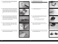
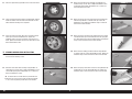
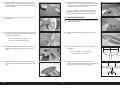
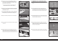
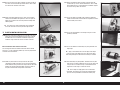
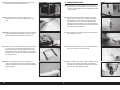
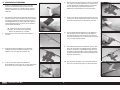
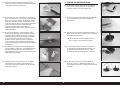
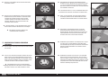
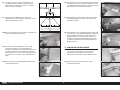
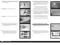
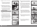
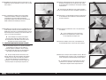
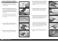
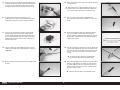
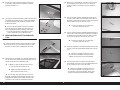
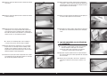
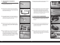
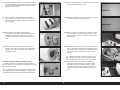
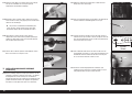
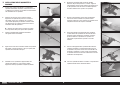
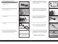
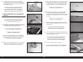
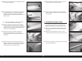
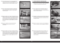
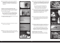
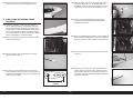
CONTROL HORN INSTALLATION
1. Insert the M3 x 15 socket head cap screw into the hole in the
aileron control horn. Remove any paint using a hobby knife
and #11 blade so the screw fi ts into the hole easily. Check all
the control horns.
2. Use medium-grit sandpaper to lightly sand the aileron control
horn where it fi ts into the aileron. Clean the sanded area
using a paper towel and isopropyl alcohol to remove any
debris or oils. This provides the surface texture necessary for
the epoxy to bond to.
Use tape on the painted area to help prevent
removing the exposed portion of the control horn.
3. Test fi t the aileron control horn in the slot in the aileron.
4. Place low-tack tape around the aileron control horn. The tape
should be 1/32-inch (1mm) from the control horn as shown.
5. Check that the horn is 90-degrees to the surface of the
aileron. If not, lightly trim the hole in the aileron to reposition
the control horn.
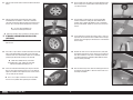
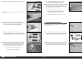
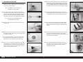
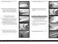
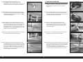
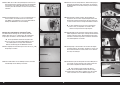
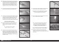
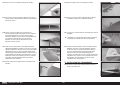
6. Remove the control horn from the control surfaces. Mix 10g
of 15-minute epoxy. Apply epoxy to the slot in the aileron and
fl ap. Make sure the epoxy gets into the slot for a good bond
between the surfaces and control horn.
7. Apply epoxy to the area of the control horn that fi ts into the
slots. Use enough epoxy so the control horns will be fully
bonded to the control surfaces.
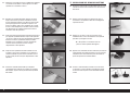
8. Before the epoxy fully cures, remove the tape from around
the control horn. This will allow the epoxy to fl ow around the
control horn, creating a small fi llet between the control horn
and surface for a fi nished look and secure bond.
9. Test fi t the remaining control horn. When gluing the control
horn, place the ball end between the horns and insert the
M3 x 15 socket head cap screw through the control horns
and rod ends. This will align the horns correctly, making the
linkage installation easier later.
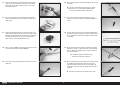
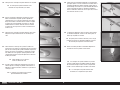
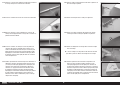
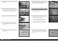
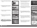
10. Insert the rudder control horn in the rudder. The tabs on the
horn will rest against the rudder.

12EN
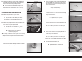
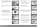
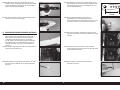
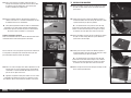
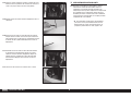
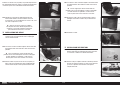
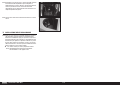
11. Use a felt-tipped pen to mark the control horn on both sides
of the rudder. This will indicate the area of the control horn
where the paint must be removed.
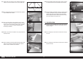
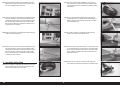
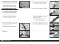
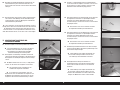
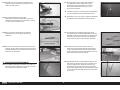
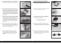
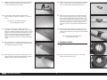
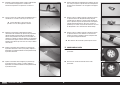
AILERON SERVO INSTALLATION
16. Remove the aileron servo cover from the wing. Tape the string
to the wing so it won’t fall into the wing.
12. Remove the control horn from the rudder. Place tape against
the lines drawn to prevent removing any unwanted paint. Use
medium-grit sandpaper to lightly sand the control horn where
it fi ts into the udder. Clean the sanded area using a paper
towel and isopropyl alcohol to remove any debris or oils. This
provides the surface texture necessary for the epoxy to bond
to.
17. Use a toothpick or hobby knife to puncture the covering for
the servo cover mounting screws.
13. Prepare the rudder by applying tape to the rudder around the
opening for the rudder control horn. Mix 10g of 15-minute
epoxy and apply it to the sanded area of the rudder control
horn. Insert the rudder control horn in the rudder. Check to
make sure the horn is centered correctly in the rudder. Allow
the epoxy to fully cure before proceeding.
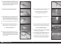
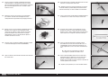
18. Use a #2 Phillips screwdriver to thread the M2.5 x 10 self-
tapping screws into the holes. Remove the screws before
proceeding to the next step.
Do not press down excessively on the
screw as it could damage the structure.
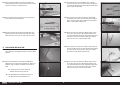
14. Prepare the remaining rudder control horn. Use the rod ends
and M3 x 15 socket head cap screws to align the second
control horn to the fi rst. Allow the epoxy to fully cure before
removing the screws and rod ends.
19. Apply a small amount of thin CA to harden the threads
made in the previous step. Allow the CA to fully cure before
installing the aileron servo cover.
15. Install the elevator control horns to complete the control horn
installation. Follow the same procedure as the aileron control
horns to install the elevator control horns.
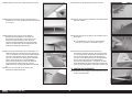
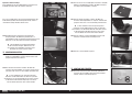
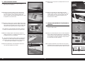
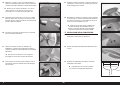
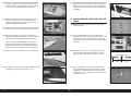
20. Center the aileron servos. Install the aluminum servo arms on
the servos perpendicular to the servo centerline. Prepare both
the right and left aileron servos.

13 EN
Cub Crafters XCub 60cc
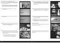
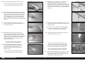
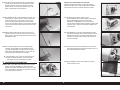
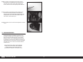
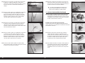
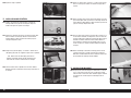
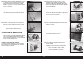
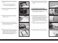
21. Fit the servo between the servo mounting tabs in the aileron
servo tray. The servo arm will be centered in the slot. Mark
the locations for the servo mounting screws using a pencil,
then remove the servo.
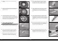
26. Use the string to pull the servo lead through the wing and out
at the root.
We left a small amount of the string on the aileron
servo lead so it can be quickly differentiated between
the flap servo lead that will be installed later.
23. Thread a servo mounting screw into each of the holes in the
servo mounting holes. Remove the screws, then apply a small
amount of thin CA to harden the threads made in the previous
step. After the CA has fully cured, secure the servo to the
cover using the screws provided with the servo.
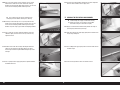
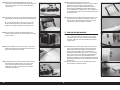
28. Use two rod ends and the 6 inch (152mm) threaded linkage
to construct two aileron pushrods. Thread the rod ends evenly
on the threaded rod. Start with the linkage the length shown
in the photo.
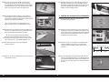
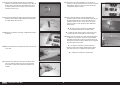
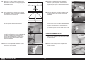
22. Use a drill and a 5/64-inch (2mm) drill bit to drill the holes
for the servo mounting screws in the locations marked in the
previous step.
27. Secure the servo to the wing using four M2.5 x 10 self-
tapping screws. Use a #2 Phillips screwdriver to tighten the
screws.
24. Secure a 24-inch (600mm) servo extension to the servo using
a commercially available retainer (SPMA3054).
25. Tie or tape the string located inside the wing to the end of the
servo lead.
29. Attach one end of the linkage to the control horn using two
M3 washers, an M3 x 15 socket head cap screw and an M3
lock nut. Tighten the hardware using a 2.5mm hex wrench
and 5.5mm nut driver.
Do not over-tighten the hardware and
damage the control horn or ball end.
30. Attach the opposite end of the linkage to the servo arm using
the hardware provided with the servo arm. Connect the
radio system to the servo and center the servo. Adjust the
linkage as necessary to center the aileron when the servo is
centered.
Repeat this section for the remaining aileron servo.

14EN
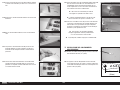
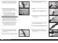
5/8 inch
(16mm)
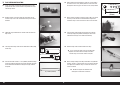
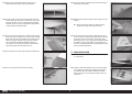
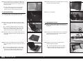
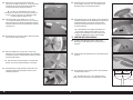
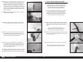
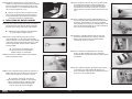
FLAP SERVO INSTALLATION
31. Center the servos and install the servo arms on the servos
perpendicular to the servo centerline. Prepare both the right
and left fl ap servos.
32. Remove the fl ap servo cover from the wing. Make sure to
mark the tray so it can be returned to the wing in the correct
direction.
33. Follow the steps outlined for the aileron servos to install the
fl ap servos.
34. The output of the fl ap servo will face toward the leading edge
of the wing.
35. Use two rod ends and the 51/2 inch (140mm) threaded linkage
to construct two fl ap pushrods. Thread the rod ends evenly on
the threaded rod. Start with the linkage the length shown in
the photo.
36. When attaching the linkage to the servo arm, use the hole in
the arm that is 5/8-inch (16mm) from the center of the arm.
Enlarge this hole using a pin vise and 1/8-inch (3mm) drill bit.
37. Attach the ball end to the servo arm using an M3 x 12 socket
head cap screw, M3 lock nut and M3 washer. Tighten the
hardware using a 2.5mm hex wrench and 5.5mm nut driver.
38. Insert the fl ap servo linkage into the wing. Place the fl ap
servo tray roughly into position, allowing the cover to be
moved so the linkage can be attached to the fl ap.
39. Guide the fl ap servo lead to the root of the wing.
Use a tie wrap or string to secure the two leads
together. This makes them less likely to fall back
into the wing, and easier to retrieve if they do.
40. Attach the fl ap linkage to the fl ap control horn using two M3
washers, an M3 x 15 socket head cap screw and an M3 lock
nut. Tighten the hardware using a 2.5mm hex wrench and
5.5mm nut driver.
Do not over-tighten the hardware and
damage the control horn or ball end.

15 EN
Cub Crafters XCub 60cc
41. Check the operation of the fl ap using the radio system. Trim
the sheeting using a hobby knife and #11 blade if any of the
hardware contacts the sheeting.
42. Secure the servo to the wing using four M2.5 x 10 self-
tapping screws. Use a #2 Phillips screwdriver to tighten the
screws.
Be careful not to press too hard and damage the structure.
43. Connect the fl ap servo to the radio system. Move the switch
on the transmitter to the “UP” fl ap position. Adjust the radio
setting to align the fl ap with the trailing edge of the wing
making sure the aileron is centered. The wing tip can be
used as a guide for aligning the aileron, or step back and look
directly at the trailing edge of the wing to make sure the fl ap
and aileron are aligned.
44. Move the switch at the transmitter to the “MID” fl ap position
of 15/16 inches (24mm). Adjust the radio settings to achieve
the setting for mid fl ap.
45. Move the switch at the transmitter to the “FULL” fl ap position
of 23/4 inches (70mm). Adjust the radio settings to achieve the
setting for full fl ap.
46. Use hobby scissors or a hobby knife with a new #11 blade to
trim the fl ap linkage cover. Use care not to chip or damage
the paint.
47. Use canopy glue or contact adhesive to attach the fl ap linage
cover to the top of the wing. Use low-tack tape to hold the
cover in position until the adhesive fully cures. Make sure to
operate the fl aps with the fairing in place to make sure fairing
does not interfere with the linkage and cause the fairing to
come loose during operation of the fl aps.
48. Use canopy glue or contact adhesive to attach the wing light
cover to the of the wing. Use low-tack tape to hold the cover
in position until the adhesive fully cures.
Do not use CA as it will fog the lens.
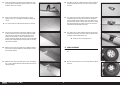
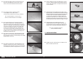
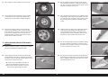
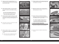
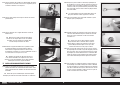
WHEEL ASSEMBLY
49. Place one of the aluminum wheel hubs in the center of the
tire.
50. Align the hub so the holes in the center align with the notches
in the tire.

16EN
51. Place the nylon bushing in position in the center of the cover.
52. Fit the remaining aluminum wheel hub into position, aligning
it with the notches in the tire. Also check to make sure the
holes around the bushing are in alignment.
53. Secure the hubs using six 4-40 x 3/4-inch stainless socket
head cap screws and six 4-40 lock nuts. Tighten the
hardware using a 3/32-inch hex wrench and 1/4-inch nut
driver. Tighten the hardware evenly so the wheel will run true
when installed on the axles.
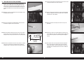
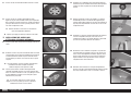
55. Attach the strut mount to the fuselage using two M3 x 15
socket head cap screws. Place a drop of threadlock on each
screw before placing them into position. Use a 2.5mm hex
wrench to tighten the screws.
Thread an M3 x 15 socket head cap screw into each
of the blind nuts. If any of the screws are difficult to thread
in, use a 3mm tap and tap handle to clear the threads.
56. Attach the strut mount to the fuselage using two M3 x 15
socket head cap screws. Place a drop of threadlock on each
screw before placing them into position. Use a 2.5mm hex
wrench to tighten the screws.
57. Attach the cross brace to the inner holes on the landing gear
mounts using two M3 x 15 socket head cap screws and
two M3 lock nuts. Tighten the hardware using a 2.5mm hex
wrench and 5.5mm nut driver.
58. Attach the sprung strut to the main landing gear using an M3
x 20 socket head cap screw and M3 lock nut. The spring will
face away from the gear when installed. Tighten the hardware
using a 2.5mm hex wrench and 5.5mm nut driver.
59. Attach the main landing gear to the mounts using two M3 x
15 socket head cap screws and two M3 lock nuts. Tighten the
hardware using a 2.5mm hex wrench and 5.5mm nut driver.
SPRUNG LANDING GEAR INSTALLATION
54. Use a hobby knife and #11 blade to remove the covering for
the strut mount mounting screws.
60. Attach the sprung struts to the cross brace using two M3 x 10
socket head cap screws and two M3 lock nuts. Tighten the
hardware using a 2.5mm hex wrench and 5.5mm nut driver.

17 EN
Cub Crafters XCub 60cc
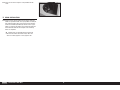
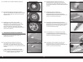
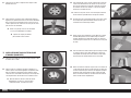
61. Slide the axle into the wheel hub from the lettered side of the
wheel.
62. Slide the axle into the main landing gear. Place a drop
of threadlock on the two M3 x 3 setscrews. Thread the
setscrews into the gear, tightening them on the fl at areas of
the axle. Use a 2mm hex wrench to tighten the setscrews.
Use care not to overtighten the
setscrews and damage the threads.
Repeat the previous steps to install the remaining wheel.
STANDARD LANDING GEAR INSTALLATION
(OPTIONAL)
63. Slide the axle bolt into the bushing from the side of the wheel
with the text.
64. Cut a hole in a piece of thin card stock and slide it on the bolt.
Place a drop of threadlock on the bolt near the card stock.
Thread the axle nut on the bolt. Don’t tighten the nut too tight,
preventing the wheel from spinning on the axle bolt.
Allow the threadlock to fully cure before
proceeding. Once cured, remove the card stock
from the bolt without disturbing the nut.
65. Secure the axle bolt to the landing gear using the axle bolt
lock nut. Use a 6mm hex wrench and 1/2-inch nut driver to
tighten the hardware. Once tightened, make sure the wheel
can spin freely on the axle bolt.
Use a 1/2-inch open end wrench if necessary to hold
the inner nut in position when tightening the hardware.
66. Check to make sure the landing gear angles toward the front
of the fuselage. The remaining wheel and landing gear strut
can now be installed.
67. Use four M4 x 25 socket head cap screws and four M4
washers to attach the landing gear to the bottom of the
fuselage. Place a drop of threadlock on each screw before
placing it into position. Tighten the screws using a 3mm hex
wrench.
68. Fit the landing gear cover to the fuselage. There is a left and
right cover, so check that the cover conforms to the fuselage
and gear. Use a felt-tipped pen to transfer the screw locations
to the fuselage.
69. Remove the cover and use a drill and 5/64-inch (2mm) drill
bit to drill the holes for the screws. Thread a screw into each
hole, then remove the screw. Place a few drops of thin CA in
each hole to harden the surrounding wood. Allow the CA to
fully cure before proceeding.
70. Once the CA has fully cured, attach the landing gear cover to
the fuselage using two M2.5 x 10 sheet metal screws and a
#2 Phillips screwdriver.

18EN
71. The remaining two screws can be installed, completing the
installation of the landing gear covers. Repeat the previous
steps to install the remaining landing gear cover.
These screws on the bottom of the fuselage are not
essential, but can be used to help the bottom of the fairing sit
closer to the fuselage. Be aware there is only a single layer
of plywood in this area so be careful not to strip the hole.
WING AND WING STRUT INSTALLATION
72. Slide the wing tube into the wing tube socket.
The wing tube may be a tight fit in the socket.
Polishing the wing tube with fine sand paper or steel
wool will help ease the installation of the wing tube.
73. Slide the wing into position on the fuselage. Guide the leads
for the ailerons and fl aps into the fuselage. Secure the wing
to the fuselage using two nylon wing bolts.
The nylon bolt can be shortened to 13/8 inches
(55mm) to make securing the wing easier.
Repeat the previous steps to attach
the remaining wing panel.
In testing, we found that a single wing bolt near the leading
edge of the wing and the installation of the wing struts was
enough to retain the wings even during sustained aerobatics.
75. Attach the strut fi tting near the aileron to the bottom of the
wing using two M3 x 15 socket head cap screws. Apply a
drop of threadlock on each screw before tightening them
using a 2.5mm hex wrench.
Do not overtighten the screws and
compress the wing sheeting.
76. Attach the strut fi tting near the leading edge to the bottom of
the wing using two M3 x 15 socket head cap screws. Apply
a drop of threadlock on each screw before tightening them
using a 2.5mm hex wrench.
Do not overtighten the screws and
compress the wing sheeting.
77. Thread the jury strut mounts into the holes in the wing. The
base of the mount will be fl ush with the bottom of the wing.
Place a drop of canopy glue on the screws before
installation. This will keep the mounts from vibrating loose.
78. Attach the wing struts to the fuselage using two M3 x 15
socket head cap screws and two M3 washers. Tighten the
screws using a 2.5mm hex wrench.
Place a drop of canopy glue on the screws before
installation. This will keep the screws from vibrating loose
yet leave them easily removable to disassemble the model.
79. Slide the outer strut fairing on the strut.
The outer strut fairings are optional as
they are a non-functional scale detail.
74. Thread an M3 x 15 socket head cap screw into each of the
blind nuts in the bottom of the wing. If any of the screws do
not thread easily, use a 3mm tap to clear the threads.

19 EN
Cub Crafters XCub 60cc
80. Thread the strut end fi tting on the threaded rod at the end of
the strut. Adjust the position of the end so there is no stress
on the strut when it is attached to the fi tting. Attach the fi tting
to the mount using an M3 x 15 socket head cap screw, two
M3 washers and an M3 locknut. Tighten the hardware using a
2.5mm hex wrench and 5.5mm nut driver.
81. Slide the outer strut fairing against the wing. Mark the
locations for the three mounting screws on the wing.
83. Once the CA has fully cured, slide the fairing back into
position. Use three M2.5 x 10 sheet metal screws and a #2
Phillips screwdriver to secure the fairing to the wing.
The front and rear struts and fairing
can be installed at this time.
85. The jury strut will fi t over the jury strut fi tting on the bottom of
the wing. Slide the pin through the strut and fi tting.
A small 1/8-inch (3mm) piece of fuel tubing
can be placed between the jury strut and head of
the pin to prevent the pin from vibrating.
86. Use a keeper to secure the jury strut to the fi tting. Secure
both the front and rear struts.
The inner strut fairings cannot be installed when the model
has been fitted with the sprung landing gear option. Skip to
the next section if the spring landing gear has been installed.
The inner strut fairings are optional as
they are a non-functional scale detail.
87. Locate the inner strut fairings. There is a left and right fairing.
Check the fi t of each fairing to make sure they are installed
on the correct sides of the fuselage.
84. Slide the jury struts on the fi tting on the main struts. The
spreader bar is located on the inside of the jury strut on the
side toward the fuselage. Use two M3 x 15 socket head cap
screws, four M3 washers and two M3 lock nuts to secure the
jury struts. Tighten the hardware using a 2.5mm hex wrench
and 5.5mm nut driver.
82. Slide the fairing on the strut. Use a drill and 5/64-inch (2mm)
drill bit to drill the holes for the outer strut fairing screws.
Prepare the holes by threading an M2.5 x 10mm sheet metal
screw in each hole. Remove the screws and apply a few
drops of thin CA in each hole to harden the surrounding wood.
Use care not to accidentally drill through the top of the wing.
88. Use a #1 Phillips screwdriver or toothpick to remove the
covering exposing the blind nuts used to secure the fairings
to the fuselage. Remove the struts from the fuselage.
Thread an M3 x 15 socket head cap screw into each
of the blind nuts. If any of the screws are difficult to thread
in, use a 3mm tap and tap handle to clear the threads.

20EN
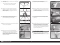
AA
A=A
AA
A=A
89. Cut two pieces of card stock that are 1/2 x 2 inches (13 x
25mm). Make a 1/8-inch (3mm) hole in each piece. Tape the
card stock to the fuselage with the hole aligned with the blind
nut in the fuselage.
90. Slide the fairing on the strut. Trace around the struts using a
felt-tipped pen.
91. Use a hobby knife and #11 blade, hobby scissors and a rotary
tool with a sanding drum to trim the fairing so the struts can
be reattached to the fuselage.
Be careful not to chip or damage the
paint on the strut fairing when cutting.
92. Hold the fairing tightly against the fuselage. Use a felt-tipped
pen to mark the locations for the mounting screws on the
fairings.
94. Fit the fairing back on the strut. Attach the struts to the
fuselage, then attach the fairing to the fuselage using two M3
x 15 socket head cap screws and two M3 washers. Tighten
the screws using a 2.5mm hex wrench.
Place a drop of canopy glue on the screws before
installation. This will keep the screws from vibrating loose
yet leave them easily removable to disassemble the model.
96. Separate the elevators from the stabilizer. Remove all the
hinges.
97. Place the stabilizer on the fuselage. Center the stabilizer on
the fuselage.
The elevator can be left in position
to aid in centering the stabilizer.
93. Disconnect the struts and remove the fairing. Use a pin vise
and 1/8-inch (3mm) drill bit to drill the mounting holes in the
fairing.
98. Stand back 8-10 feet (2-3 meters) and check that the
stabilizer is aligned with the wing. Lightly sand the stabilizer
saddle on the fuselage to correct any misalignment.
STABILIZER INSTALLATION
95. Place a small piece of tape on the bottom of the stabilizer and
elevator for identifi cation.
La pagina sta caricando ...
La pagina sta caricando ...
La pagina sta caricando ...
La pagina sta caricando ...
La pagina sta caricando ...
La pagina sta caricando ...
La pagina sta caricando ...
La pagina sta caricando ...
La pagina sta caricando ...
La pagina sta caricando ...
La pagina sta caricando ...
La pagina sta caricando ...
La pagina sta caricando ...
La pagina sta caricando ...
La pagina sta caricando ...
La pagina sta caricando ...
La pagina sta caricando ...
La pagina sta caricando ...
La pagina sta caricando ...
La pagina sta caricando ...
La pagina sta caricando ...
La pagina sta caricando ...
La pagina sta caricando ...
La pagina sta caricando ...
La pagina sta caricando ...
La pagina sta caricando ...
La pagina sta caricando ...
La pagina sta caricando ...
La pagina sta caricando ...
La pagina sta caricando ...
La pagina sta caricando ...
La pagina sta caricando ...
La pagina sta caricando ...
La pagina sta caricando ...
La pagina sta caricando ...
La pagina sta caricando ...
La pagina sta caricando ...
La pagina sta caricando ...
La pagina sta caricando ...
La pagina sta caricando ...
La pagina sta caricando ...
La pagina sta caricando ...
La pagina sta caricando ...
La pagina sta caricando ...
La pagina sta caricando ...
La pagina sta caricando ...
La pagina sta caricando ...
La pagina sta caricando ...
La pagina sta caricando ...
La pagina sta caricando ...
La pagina sta caricando ...
La pagina sta caricando ...
La pagina sta caricando ...
La pagina sta caricando ...
La pagina sta caricando ...
La pagina sta caricando ...
La pagina sta caricando ...
La pagina sta caricando ...
La pagina sta caricando ...
La pagina sta caricando ...
La pagina sta caricando ...
La pagina sta caricando ...
La pagina sta caricando ...
La pagina sta caricando ...
La pagina sta caricando ...
La pagina sta caricando ...
La pagina sta caricando ...
La pagina sta caricando ...
La pagina sta caricando ...
La pagina sta caricando ...
La pagina sta caricando ...
La pagina sta caricando ...
La pagina sta caricando ...
La pagina sta caricando ...
La pagina sta caricando ...
La pagina sta caricando ...
La pagina sta caricando ...
La pagina sta caricando ...
La pagina sta caricando ...
La pagina sta caricando ...
La pagina sta caricando ...
La pagina sta caricando ...
La pagina sta caricando ...
La pagina sta caricando ...
La pagina sta caricando ...
La pagina sta caricando ...
La pagina sta caricando ...
La pagina sta caricando ...
La pagina sta caricando ...
La pagina sta caricando ...
La pagina sta caricando ...
La pagina sta caricando ...
La pagina sta caricando ...
La pagina sta caricando ...
La pagina sta caricando ...
La pagina sta caricando ...
La pagina sta caricando ...
La pagina sta caricando ...
La pagina sta caricando ...
La pagina sta caricando ...
La pagina sta caricando ...
La pagina sta caricando ...
La pagina sta caricando ...
La pagina sta caricando ...
-
 1
1
-
 2
2
-
 3
3
-
 4
4
-
 5
5
-
 6
6
-
 7
7
-
 8
8
-
 9
9
-
 10
10
-
 11
11
-
 12
12
-
 13
13
-
 14
14
-
 15
15
-
 16
16
-
 17
17
-
 18
18
-
 19
19
-
 20
20
-
 21
21
-
 22
22
-
 23
23
-
 24
24
-
 25
25
-
 26
26
-
 27
27
-
 28
28
-
 29
29
-
 30
30
-
 31
31
-
 32
32
-
 33
33
-
 34
34
-
 35
35
-
 36
36
-
 37
37
-
 38
38
-
 39
39
-
 40
40
-
 41
41
-
 42
42
-
 43
43
-
 44
44
-
 45
45
-
 46
46
-
 47
47
-
 48
48
-
 49
49
-
 50
50
-
 51
51
-
 52
52
-
 53
53
-
 54
54
-
 55
55
-
 56
56
-
 57
57
-
 58
58
-
 59
59
-
 60
60
-
 61
61
-
 62
62
-
 63
63
-
 64
64
-
 65
65
-
 66
66
-
 67
67
-
 68
68
-
 69
69
-
 70
70
-
 71
71
-
 72
72
-
 73
73
-
 74
74
-
 75
75
-
 76
76
-
 77
77
-
 78
78
-
 79
79
-
 80
80
-
 81
81
-
 82
82
-
 83
83
-
 84
84
-
 85
85
-
 86
86
-
 87
87
-
 88
88
-
 89
89
-
 90
90
-
 91
91
-
 92
92
-
 93
93
-
 94
94
-
 95
95
-
 96
96
-
 97
97
-
 98
98
-
 99
99
-
 100
100
-
 101
101
-
 102
102
-
 103
103
-
 104
104
-
 105
105
-
 106
106
-
 107
107
-
 108
108
-
 109
109
-
 110
110
-
 111
111
-
 112
112
-
 113
113
-
 114
114
-
 115
115
-
 116
116
-
 117
117
-
 118
118
-
 119
119
-
 120
120
-
 121
121
-
 122
122
-
 123
123
-
 124
124


Hangar 9 HAN5260B Manuale del proprietario
- Categoria
- Giocattoli telecomandati
- Tipo
- Manuale del proprietario
in altre lingue
- English: Hangar 9 HAN5260B Owner's manual
- français: Hangar 9 HAN5260B Le manuel du propriétaire
- Deutsch: Hangar 9 HAN5260B Bedienungsanleitung
Documenti correlati
-
 Hangar 9 HAN5260 Manuale del proprietario
-
 Hangar 9 HAN2530 Manuale del proprietario
-
 Hangar 9 HAN2390 Manuale del proprietario
-
 Hangar 9 HAN3390 Manuale utente
-
 Hangar 9 HAN5280 Manuale del proprietario
-
 Hangar 9 HAN4670 Manuale del proprietario
-
 Hangar 9 HAN4720CR Manuale del proprietario
-
 Hangar 9 HAN2890 Manuale del proprietario
-
 Hangar 9 HAN4770 Manuale del proprietario


