
Manuale installatore
Dispositivo programmabile con due relè art. 69PH
Installer guide
Programmable device with two relat art. 69PH

2
INDICE
Introduzione.................................................................................................2
Descrizione..................................................................................................2
Caratteristiche tecniche ................................................................................................2
Programmazioni MANUALI BUS DueFiliElvox standard o BUS VERTICALE..............3
Programmazioni con PROGR. BUS DueFiliElvox standard o BUS VERTICALE....5
Programmazioni MANUALI BUS DueFiliElvox ORIZZONTALE ..............................9
Programmazioni con PROGR. BUS DueFiliElvox ORIZZONTALE..........................9
Programmazioni con 950C..........................................................................................11
Programmazioni con PC e Software SaveProg...........................................................12
Descrizione ag e check box Software SaveProg ....................................................13
Diagramma delle programmazioni in italiano...............................................................14
Diagramma delle programmazioni in inglese...............................................................16
Schemi di collegamento ............................................................................................18
Avvertenze e Direttive ..................................................................................................19
Introduzione
Il Modulo relè 69PH, è un dispositivo programmabile al cui interno sono presenti due
attuatori (relè). La configurazione dei due attuatori può avvenire con modalità indipen-
dente o in correlazione. Il Modulo relè 69PH può essere impiegato in impianti Due-
FiliElvox standard/tradizionali o in impianti “estesi”. Il funzionamento in impianti con
configurazione tradizionale e configurazione estesa (con collegamento al BUS VER-
TICALE) V è analogo.
Il funzionamento di un relè 69PH in un impianto “esteso” con collegamento su BUS
ORIZZONTALE è legato oltre alla programmazione del Modulo relè 69PH ed alla con-
figurazione del router 69RS di riferimento (vedi istruzione di prodotto). Le modalità di
funzionamento del relè 69PH su BUS ORIZZONTALE, sono trattate nei capitoli dedi-
cati. Il Modulo relè è configurabile con il programmatore 950C o attraverso l’ausilio di
un PC (con installato il software SaveProg) e l’interfaccia 692I/U.
Descrizione
La programmazione delle funzioni base può avvenire in modo manuale nel collega-
mento su Bus verticale. Per le programmazioni avanzate deve essere utilizzato il pro-
grammatore 950C o PC con SaveProg. Nel funzionamento su Bus verticale, il Modulo
relè può essere utilizzato come relè o ripetitore di chiamata (tutte le modalità).
La programmazione per collegamento su Bus Orizzontale, può avvenire solo attraverso
programmatore 950C o PC con SaveProg. Nel funzionamento con collegamento con
il Bus orizzontale, può essere utilizzato come relè (tutte le modalità) e come ripetitore
di chiamata esclusivamente per i dati inviati da un’unità elettronica collegata al Bus
orizzontale, verso uno specifico posto interno.
Nota: Quando il Modulo relè 69PH è collegato al Bus Orizzontale, l’unica programma-
zione MANUALE possibile è il RESET delle configurazioni introdotte, azzerando i dati
inseriti e tornando alla configurazione di default .
Nota: il Modulo relè 69PH viene commercializzato con una configurazione di Default
riferita all’ INSTALLAZIONE su BUS VERTICALE.
Caratteristiche tecniche
- Carico massimo dei contatti (ai morsetti 1C/NO/NC, 2C/NO/NC): 230V 6A / AC1
- Alimentazione da Bus Due Fili
- Assorbimento:
• 1,8mA in standby
• 15mA in funzionamento
• 80mA per 80ms (corrente di picco)
- Temperatura di esercizio: 0 - 40°C
- Installabile su guida DIN (60715 TH35) o a parete
- Dimensioni 70x115x50 mm
PROGRAMMAZIONI MANUALI - BUS VERTICALE
1) Ripristino dati di default
2) Relè monostabile con attivazione dai tasti dei posti interni (config. di default)
3) Ripetitore di chiamata
4) Attribuzione ID
PROGRAMMAZIONI CON PROGRAMM. ART. 950C O CON
SOFTWARE “SAVEPROG” - BUS VERTICALE
5) Relè monostabile con attivazione dai tasti dei posti interni (config. di default)
6) Relè monostabile attivato da chiamata
7) Relè monostabile attivato dai tasti F1, F2, serratura del posto interno
8) Relè monostabile attivato da tentativo di chiamata
9) Relè monostabile attivato da tentativo di chiamata a gruppo
10) Relè bistabile con attivazione da tasti posti interni
11) Relè bistabile attivato da chiamata
12) Ripetitore di chiamata (Standard)
13) Ripetitore di chiamata generico
14) Ripetitore di chiamata da art. 6120
15) Modalità Tapparella
16) Mappa delle abilitazioni
CONTENTS
Introduction .................................................................................................................. 2
Description................................................................................................................... 2
Technical characteristics ............................................................................................. 2
MANUAL programming standard Elvox DueFili BUS or VERTICAL BUS ................... 3
Programming with PROG. standard Elvox DueFili BUS or VERTICAL BUS............... 5
MANUAL programming HORIZONTAL Elvox DueFili BUS ........................................ 9
Programming with PROG. HORIZONTAL Elvox DueFili BUS ..................................... 9
Programming with 950C .............................................................................................11
Programming with PC and SaveProg Software......................................................... 12
Description of ags and check boxes for SaveProg Software .................................. 13
Diagram of programming in Italian ............................................................................ 14
Diagram of programming in English .......................................................................... 16
Wiring diagrams ........................................................................................................ 18
Warnings and Guidelines ......................................................................................... 19
Introduction
The relay module 69PH is a programmable device in which there are two actuators
(relays). The configuration of the two actuators can be done independently or in conjun-
ction. The relay module 69PH can be used in standard/traditional Elvox DueFili systems
or in "extended" systems. Operation in systems with a traditional configuration or an
extended configuration (with connection to VERTICAL BUS) V is similar.
The operation of a 69PH relay in an "extended" system with connection over HORIZON-
TAL BUS depends not only on the programming of the relay module 69PH but also on
the configuration of the reference router 69RS (see product instructions). The operating
mode of the relay 69PH over HORIZONTAL BUS is dealt with in the specific chapters.
The relay module is configurable with the programmer 950C or with the aid of a PC (with
the SaveProg software installed) and the interface 692I/U.
Description
The basic functions can be programmed manually in the connection over vertical bus.
Advanced programming requires using the programmer 950C or a PC with SaveProg.
With operation over vertical Bus, the relay module can be used as a relay or call repe-
ater (all modes).
Programming for connection over Horizontal Bus can only be via the programmer 950C
or a PC with SaveProg. In operation with connection over Horizontal Bus, it can be used
as a relay (all modes) and as a call repeater solely for data sent from an electronic unit
connected to the horizontal bus to a specific indoor station.
Note: When the relay module 69PH is connected to the Horizontal Bus, the only possi-
ble MANUAL programming is to RESET the configurations made, resetting the entered
data and returning to the default configuration.
Note: The relay module 69PH is marketed with a default configuration referred to IN-
STALLATION over VERTICAL BUS.
Technical characteristics
- Maximum load across contacts (terminals 1C/NO/NC, 2C/NO/NC): 230V 6A / AC1
- Due Fili Bus power supply
- Absorption:
• 1.8mA on standby
• 15mA in operation
• 80mA for 80ms (peak current)
- Operating temperature: 0 - 40°C
- Can be installed on (60715 TH35) DIN rails or on a wall
- Dimensions 70x115x50 mm
MANUAL PROGRAMMING- VERTICAL BUS
1) Reset default data
2) Monostable relay with activation by buttons on the indoor stations (default config.)
3) Call repeater
4) ID assignment
PROGRAMMING WITH PROGRAMMER ART. 950C OR "SAVEPROG"
SOFTWARE - VERTICAL BUS
5) Monostable relay with activation by buttons on the indoor stations (default config.)
6) Call-activated monostable relay
7) Monostable relay activated by F1, F2 or lock buttons on the indoor station
8) Monostable relay activated by call attempt
9) Monostable relay activated by attempt to call group
10) Bistable relay with activation by indoor station buttons
11) Call-activated bistable relay
12) Call repeater (standard)
13) Generic call repeater
14) Call repeater from art. 6120
15) Roller shutter mode
16) Enabling map
Le manuel d’installation peut être téléchargé à partir de www.vimar.com
.
Die Betriebsanleitung ist von der Website herunter-
geladen werden www.vimar.com
.
El manual de instalación se puede descargar desde www.vimar.com
.
O manual de instalador
pode ser baixado a partir de www.vimar.com
.
Το εγχειρίδιο εγκατάστασης μπορεί να μεταφορτωθεί από www.vimar.com

3
ATTENZIONE: prima di procedere al collegamento ed alla programmazione leggere
attentamente le istruzioni per avere un quadro completo sulle caratteristiche, funzioni
e prestazioni dell’apparecchiatura.
PROGRAMMAZIONI MANUALI BUS VERTICALE
1) RIPRISTINO DATI DI DEFAULT
La procedura di Reset permette di tornare alle impostazioni di fabbrica (configurazione
di default).
- Premere e mantenere premuti contemporaneamente i tasti RST e P1.
- Rilasciare RST mantenendo premuto P1 fino a quando il led inizia a lampeggiare.
- Mentre il led lampeggia rilasciare P1 e subito ripremere P1.
- Mantenere P1 premuto fino a quando il led si spegne.
- Rilasciare P1.
NOTA: nella configurazione di Default, la modalità di funzionamento è di relè monosta-
bile con attivazione dai tasti del posto interno.
2) RELÈ MONOSTABILE CON ATTIVAZIONE DEI TASTI DA POSTO INTERNO
Il relè RL1 si attiva premendo il tasto P2 del posto interno, il relè RL2 viene attivato dal
tasto P3 del posto interno. Tutti i posti interni che prevedono i tasti P2 e P3 opportuna-
mente configurati, possono attivare RL1 e RL2.
Esempio: premendo il tasto P2, trascorso il tempo di ritardo T1, si attiva il relè RL1,
rimane attivo per un tempo T2, dopo di che torna a riposo (nella posizione iniziale).
Lo stesso funzionamento vale per il tasto P3 che attiva RL2 con le stesse modalità
appena descritte.
3) RIPETITORE DI CHIAMATA
Il relè RL1 ripete le chiamate che arrivano ad un posto interno da un’unità elettronica
esterna. Il relè RL2 ripete le chiamate intercomunicanti. Al relè deve essere assegnato
un identificativo del Gruppo riferito all’ID del posto interno . Il relè si attiva seguendo il
ritmo di chiamata.
CONNETTORE
PROGRAMMAZIONE
CON 950C O
SAVEPROG
12 B1 B2
MORSETTIERA BUS
ID
DIP SWITCH
ATTRIBUZIONE
ID
RST
P1
PULSANTE
DI RESET
PULSANTE DI
PROGRAMMAZIONE
LED INDICATORE
STAT O DELLA
PROGRAMMAZIONE
C
BA
TERMINAZIONE
SEGNALE VIDEO
1C NO NC 2C NO NC
ON
OFF
123
4
Tasto di
programmazione
Contatto
Relè RL2
Morsettiera
BUS
DUE FILI
Connettore
terminazione
BUS DUE FILI
Segnalazione
programmazione
Dip-switch
attribuzione ID
Contatto
Relè RL1
Connettore di colle-
gamento
programmatore
950C /
SaveProg / EVCom
ATTENZIONE: disposi-
tivo sensibile alle scari-
che elettrostatiche.
Tasto di
Reset
gura 1
Il relè termina la ripetizione della chiamata quando:
- L’unità elettronica completa i cicli suoneria programmati (chiamata esterna)
- Il relè giunge al termine del numero di cicli programmati (default 5)
- Alla risposta.
CHIAMATA DA ESTERNO
CHIAMATA INTERNA
1s ON
2s OFF
1s ON
4s OFF
1s ON
2s OFF
1s ON
4s OFF
Chiamata
da esterno
Chiamata
interna
Nel caso siano appena descritto verrà utilizzato l’identificativo ID di default, nel caso
siano presenti più relè 69PH nell’impianto. Per i posti interni dotati di più tasti, questi
potranno essere opportunamente configurati (vedi istruzioni posti interni) creando dei
GRUPPI al fine di poter pilotare più attivazioni (relè) da un unico posto interno.
gura 2
CAUTION: Before commencing connecting and programming, read the instructions
carefully to get a clear idea of the equipment's characteristics, functions and features.
VERTICAL BUS MANUAL PROGRAMMING
1) RESET DEFAULT DATA
The reset procedure allows factory settings to be restored (default configuration).
- Press and hold down buttons RST and P1 simultaneously.
- Release RST but continue to hold down P1 until the LED begins to flash.
- While the LED flashes release P1 and press P1 immediately again.
- Hold down P1 until the LED goes out.
- Release P1.
NOTE: In the Default configuration, the operating mode is as a monostable relay with
activation by the indoor station buttons.
2) MONOSTABLE RELAY WITH ACTIVATION OF BUTTONS ON INDOOR STATION
Relay RL1 is activated by pressing button P2 on the indoor station, relay RL2 by pres-
sing button P3 on the indoor station. All the indoor stations that have buttons P2 and
P3 suitably configured can activate RL1 and RL2.
Example: on pressing button P2, after the delay time T1 the relay RL1 is activated and
remains active for a time T2, after which it returns to rest (initial position). The same ope-
ration applies for button P3, which activates RL2 in the same way as described above.
3) CALL REPEATER
Relay RL1 repeats calls arriving at an indoor station from an external electronic unit.
Relay RL2 repeats intercommunicating calls. The relay must be assigned a Group ID
referring to the ID of the indoor station. The relay activates following the call sequence.
The relay terminates call repetition when:
- The electronic unit completes the programmed chime cycles (external call)
- The relay reaches the end of the number of programmed cycles (default 5)
- On answering.
CHIAMATA DA ESTERNO
CHIAMATA INTERNA
1s ON
2s OFF
1s ON
4s OFF
1s ON
2s OFF
1s ON
4s OFF
Call
from outside
Call
from inside
In
the case that has just been described the default ID will be used, if there is more
than one 69PH relay in the system. For indoor stations with multiple buttons, the but-
tons can be suitably configured (see indoor station instructions) creating GROUPS in
order to drive multiple activations (relays) from a single indoor station.
Figure 2
CONNETTORE
PROGRAMMAZIONE
CON 950C O
SAVEPROG
12 B1 B2
MORSETTIERA BUS
ID
DIP SWITCH
ATTRIBUZIONE
ID
RST
P1
PULSANTE
DI RESET
PULSANTE DI
PROGRAMMAZIONE
LED INDICATORE
STAT O DELLA
PROGRAMMAZIONE
C
BA
TERMINAZIONE
SEGNALE VIDEO
1C NO NC 2C NO NC
ON
OFF
123
4
Key for
programming
Contact
Relay RL2
Terminal block
BUS
TWO-WIRE
Connector
termination
TWO-WIRE BUS
Signal for
programming
Dip-switch
ID assignment
Contact
Relay RL1
Connector for con-
necting
programmer 950C /
SaveProg / EVCom
CAUTION: Device
sensitive to electrostatic
discharges.
Key for
Reset
Figure 1
Morsettiere componenti
Component terminal blocks

4
Esempio: assegnando al Gruppo 1 del relè l’ID = 8, RL1 o RL2 si attivano all’arrivo di
una chiamata verso il posto interno con ID = 8. Ad una chiamata da unità elettronica
si attiva il relè RL1, mentre ad una chiamata da un apparecchio intercomunicante si
attiva RL2.
Programmazione ID per installazione su Bus Verticale
Il relè dispone di 4 gruppi, per cui può attivarsi per quattro ID diversi.
Tabella Programmazione ID
Gruppo Dip 1 Dip 2 Dip 3 Dip 4
Gruppo 1 OFF OFF OFF ON
Gruppo 2 ON OFF OFF ON
Gruppo 3 OFF ON OFF ON
Gruppo 4 ON ON OFF ON
Esempio: (Gruppo 1 – posto interno ID = 8)
1) Portare il dip-switch 4 in posizione ON per indicare programmazione.
2) Portare i dip-switch 1, 2 e 3 su OFF per selezionare il GRUPPO 1.
3) Premere P1 fino a quando si accende il led a luce fissa.
4) Rilasciare P1.
5) Premere il tasto serratura del posto interno ID 8 (ID di esempio per le istruzioni), il
led inizia a lampeggiare
6) Premere nuovamente P1 fino a quando il led si spegne.
7) Rilasciare P1.
Ora l’ID è stato assegnato.
8) Rimettere il dip-switch 4 su OFF.
Il relè dispone di 8 Gruppi indipendenti per RL1 e RL2. In fase di programmazione
l’ID viene assegnato automaticamente sia a RL1 che RL2. La procedura di cancel-
lazione invece, deve essere fatta distintamente per RL1 e per RL2.
Cancellazione ID
Tabella cancellazione ID relè RL1
Gruppo Dip 1 Dip 2 Dip 3 Dip 4
Gruppo 1 Relè 1 OFF OFF OFF OFF
Gruppo 2 Relè 1 ON OFF OFF OFF
Gruppo 3 Relè 1 OFF ON OFF OFF
Gruppo 4 Relè 1 ON ON OFF OFF
Tabella cancellazione ID relè RL2
Gruppo Dip 1 Dip 2 Dip 3 Dip 4
Gruppo 1 Relè 2 OFF OFF ON OFF
Gruppo 2 Relè 2 ON OFF ON OFF
Gruppo 3 Relè 2 OFF ON ON OFF
Gruppo 4 Relè 2 ON ON ON OFF
Esempio: cancellare l’ID appena assegnato (Gruppo 1 – Relè 1 e Gruppo 1 – Relè 2)
1) Portare il dip-switch 4 in posizione OFF per indicare cancellazione.
2) Selezionare il GRUPPO 1 di RL1 portando i Dip-switch 1, 2 e 3 in posizione OFF.
3) Premere P1 fino a quando si accende il led.
4) Quando il led si spegne rilasciare il tasto P1.
A questo punto è stato resettata la programmazione di RL1.
5) Per RL2 selezionare il GRUPPO 1 di RL2 con Dip-switch 1 e 2 in posizione OFF e
Dip-switch 3 in posizione ON.
6) premere P1 fino a quando si accende il led.
7) Quando il led si spegne rilasciare il tasto P1.
A questo punto è stato resettata la programmazione anche di RL2.
8) Rimettere tutti i dip-switch su OFF.
NOTA: è possibile cancellare tutte le programmazioni presenti nel 69PH contempora-
neamente utilizzando la procedura di “RIPRISTINO DATI DI DEFAULT”.
NOTA: l’attribuzione dell’ identificativo ID con 69PH installato sul Bus Orizzontale , può
avvenire solo con programmatore 950C o SaveProg.
4) ATTRIBUZIONE ID PER FUNZIONAMENTO DEI RELÈ PER PRESENZA DI PIÙ
69PH NELL’IMPIANTO
L’ID del dispositivo 69PH di default è 1
Nel funzionamento come RELE’, possono essere presenti fino a otto 69PH nell’im-
pianto, per un totale di 16 attuatori, in questo caso con i Dip-switch deve essere asse-
gnato un identificativo ID ad ogni modulo 69PH. Il posto interno deve avere più tasti
opportunamente programmati per attivare relè ausiliari.
NOTA: più relè possono essere programmati con lo stesso ID se c’è la necessità di
attivazioni contemporanee comandate dallo stesso tasto.
NOTA: RL1 e RL2 in configurazione DEFAULT vengono attivati dai tasti del posto
interno P2 e P3 corrispondenti ad AUX 1 e AUX2 di ogni GRUPPO configurato.
L’attribuzione manuale dell’identicativo ID del Modulo relè 69PH, avviene attraverso
il settaggio dei “Dip-switch di attribuzione identicativo ID”. Per la congurazione fare
riferimento a gura 1 ed a tabella 4.
Tabella 1
Tabella 2Tabella 3
Example: if ID = 8 is assigned to Group 1 of relay, RL1 or RL2 activate on arrival of a
call to an indoor station with ID = 8. A call from an electronic unit activates relay RL1,
whereas a call from an intercom device activates RL2.
Programming ID for installation on Vertical Bus
The relay has 4 groups, so it can be activated for four different IDs.
ID programming table
Group Dip 1 Dip 2 Dip 3 Dip 4
Group 1 OFF OFF OFF ON
Group 2 ON OFF OFF ON
Group 3 OFF ON OFF ON
Group 4 ON ON OFF ON
Example: (Group 1 – indoor station ID = 8)
1) Set dip switch 4 in ON position to indicate programming.
2) Set dip switches 1, 2 and 3 on OFF to select GROUP 1.
3) Press and hold down P1 until the LED illuminates steadily.
4) Release P1.
5) Press door lock button on indoor station ID 8 (example ID for the instructions); the
LED will begin to flash
6) Press and hold down P1 again until the LED goes off.
7) Release P1.
The ID is now assigned.
8) Set dip-switch 4 back onto OFF.
The relay has 8 independent groups for RL1 and RL2. During programming, the
ID is assigned automatically to both RL1 and RL2. The cancellation procedure,
however, must be preformed separately for RL1 and RL2.
ID cancellation
Relay RL1 ID cancellation table
Group Dip 1 Dip 2 Dip 3 Dip 4
Group 1 Relay 1 OFF OFF OFF OFF
Group 2 Relay 1 ON OFF OFF OFF
Group 3 Relay 1 OFF ON OFF OFF
Group 4 Relay 1 ON ON OFF OFF
Relay RL2 ID cancellation table
Group Dip 1 Dip 2 Dip 3 Dip 4
Group 1 Relay 2 OFF OFF ON OFF
Group 2 Relay 2 ON OFF ON OFF
Group 3 Relay 2 OFF ON ON OFF
Group 4 Relay 2 ON ON ON OFF
Example: cancelling the ID that has just been assigned (Group 1 – Relay 1 and Group
1 – Relay 2)
1) Set dip switch 4 in OFF position to indicate cancellation.
2) Select GROUP 1 of RL1 by setting dip switches 1, 2 and 3 in the OFF position.
3) Press and hold down P1 until the LED lights up.
4) When the LED goes off, release button P1.
RL1 programming has now been reset.
5) For RL2, select GROUP 1 of RL2 by setting dip switches 1 and 2 in the OFF position
and dip switch 3 in the ON position.
6) Press and hold down P1 until the LED lights up.
7) When the LED goes off, release button P1.
RL2 programming has now also been reset.
8) Set all the dip-switches back onto OFF.
NOTE: All programming on 69PH can be cancelled simultaneously using the “RESET
DEFAULT DATA” procedure.
NOTE: The ID with 69PH installed over Horizontal Bus can only be assigned with pro-
grammer 950C or SaveProg.
4) ID ATTRIBUTION FOR RELAY OPERATION IF MORE THAN ONE 69PH IS PRE-
SENT IN THE SYSTEM
The default ID of device 69PH is 1
When operating as RELAYS, there may be up to eight 69PH modules in the system,
to a total of 16 actuators. In this case the dip switches must be used to assign an ID to
each 69PH module. The indoor station must have multiple suitably programmed buttons
to activate auxiliary relays.
NOTE: More than one relay can be programmed with the same ID if simultaneous
activations controlled by the same button are required.
NOTE: RL1 and RL2 are activated in the DEFAULT configuration by buttons P2 and P3
on the indoor station, corresponding to AUX 1 and AUX 2 of each configured GROUP.
The ID of the relay module 69PH is manually assigned by setting the "Dip-switch for
assigning ID." For the conguration please refer to Figure 1 and Table 4.
Table 1
Table 2Table 3

5
PROGRAMMAZIONI CON PROGRAMMATORE ART.
950C / “SAVEPROG” - BUS VERTICALE
5) RELÈ MONOSTABILE CON ATTIVAZIONE DA TASTI DEL POSTO INTERNO
È la modalità di funzionamento programmata di fabbrica. I relè si attivano con un ri-
tado T1 e rimangono attivi per un tempo T2 poi tornano a riposo.
Il relè RL1 si attiva premendo il tasto P2 del posto interno, il relè RL2 viene attivato dal
tasto P3 del posto interno. Tutti i posti interni che prevedono i tasti P2 e P3 opportuna-
mente configurati, possono attivare RL1 e RL2.
I relè RL1 e RL2 possono funzionare in questa modalità anche singolarmente.
6) RELÈ MONOSTABILE ATTIVATO DA CHIAMATA
Il relè viene attivato dall’invio di un chiamata ad un posto interno presente nell’impianto
che accetta la chiamata. Si attiva con un tempo di ritardo T1 rispetto all’invio della
chiamata e rimane attivo per un tempo T2. Dopo di che il relè torna nella posizione
iniziale. I dispositivi che inviano la chiamata e i dispositivi che ricevono la chiamata sono
configurabili da “mappa delle abilitazioni”.
Per default tutti i dispositivi sono abilitati.
7) RELÈ MONOSTABILE ATTIVATO DAI TASTI F1, F2, SERRATURA DEL POSTO
INTERNO
Il relè si attiva quando viene inviato il comando apertura serratura o F1 o F2 premendo il
tasto corrispondente del posto interno. Il relè si attiva con ritardo T1 rispetto la ricezione
del comando e rimane attivo per un tempo T2.
I dispositivi che inviano il comando e quelli che sono destinatari del comando sono con-
figurabili secondo la “Mappa delle abilitazioni”. Per default tutti i dispositivi sono abilitati.
8) RELÈ MONOSTABILE ATTIVATO DA TENTATIVO DI CHIAMATA
Il relè si attiva all’invio di una chiamata ad un dispositivo che può non essere presente
nell’impianto o rifiutare la chiamata. Il relè si attiva con un tempo di ritardo T1 rispetto
all’invio della chiamata e rimane attivo per il tempo T2. I dispositivi che inviano la chia-
mata e quelli che ricevono la chiamata sono abilitati da “Mappa delle abilitazioni”. Per
default tutti i dispositivi sono abilitati.
9) RELÈ MONOSTABILE ATTIVATO DA TENTATIVO DI CHIAMATA A GRUPPO
Il relè si attiva all’invio di una chiamata ad un posto interno che può non essere presente
nell’impianto o rifiutare la chiamata. Il relè si attiva con un tempo di ritardo T1 rispetto
all’invio della chiamata e rimane attivo per il tempo T2.
L’ID del posto interno destinatario della chiamata deve essere programmato nel para-
metro “GRUPPO”. È possibile avere fino ad 8 posti interni diversi.
10) RELÈ BISTABILE CON ATTIVAZIONE DA TASTI POSTO INTERNO
Il relè commuta il suo stato ogni volta che riceve un comando a lui indirizzato (vedi
paragrafo 4 “Tabella programmazione ID”).
Esempio: il relè RL1 non è attivo, il tasto P2 è stato programmato per attivare AUSI-
LIARIO 1. Premendo P2, RL1 si attiva con un ritardo T1. Premendo nuovamente P2
il relè si disattiva con un ritardo T2. In questa modalità di funzionamento il RELE’ può
inviare un messaggio di conferma dell’avvenuta commutazione al dispositivo che lo ha
attivato, attivando il flag “Not. Stato”.
11) RELÈ BISTABILE ATTIVATO DA CHIAMATA ACCETTATA
Il relè si attiva all’invio di una chiamata ad un dispositivo presente sull’impianto che
accetta la chiamata.
La disattivazione del relè può avvenire in modo diverso a seconda dello stato del Flag
“Chiam. Int”:
- Se il Flag “Chiam. Int” = NO: il relè si disattiva al completamento dei cicli suoneria
impostati sulla unità elettronica (se chiamata esterna) oppure alla risposta alla chia-
mata oppure al termine della chiamata.
- Se il Flag “Chiam. Int” = SI: il relè si disattiva solo al termine della chiamata.
I dispositivi che inviano la chiamata e quelli che ricevono la chiamata sono abilitabili da
“Mappa delle abilitazioni”. Per default tutti i dispositivi sono abilitati.
12) RIPETITORE DI CHIAMATA STANDARD
Il relè RL1 ripete le chiamate che arrivano al posto interno da una unità elettronica
esterna. Il relè RL2 ripete le chiamate interne.
Per far funzionare il relè in questa modalità è necessario assegnare l’ID al parametro
GRUPPO del relè 1 e al corrispondente parametro GRUPPO del relè 2 l’ID del dispo-
sitivo che riceve la chiamata. In ogni GRUPPO l’ID di RL1 e RL2 deve corrispondere.
Esempio:
- Gruppo 1 RL1 = Gruppo 1 RL2 = 1
- Gruppo 2 RL1 = Gruppo 2 RL2 = 3
- Gruppo 3 RL1 = Gruppo 3 RL2 = 0
- Gruppo 4 RL1 = Gruppo 4 RL2 = 0
Il relè RL1 si attiva per la chiamata esterna all’ID 1 e 3.
Il relè RL2 si attiva per la chiamata interna all’ID 1 e 3.
69PH Funzionamento Dip 1 Dip 2 Dip 3 Dip 4
1 (ID 1)
RL1=Ausiliario 1 e RL2=Ausiliario 2
OFF OFF OFF OFF
2 (ID 2)
RL1=Ausiliario 3 e RL2=Ausiliario 4
ON OFF OFF OFF
3 (ID 3)
RL1=Ausiliario 5 e RL2=Ausiliario 6
OFF ON OFF OFF
4 (ID 4)
RL1=Ausiliario 7 e RL2=Ausiliario 8
ON ON OFF OFF
5 (ID 5)
RL1=Ausiliario 9 e RL2=Ausiliario 10
OFF OFF ON OFF
6 (ID 6)
RL1=Ausiliario 11 e RL2=Ausiliario 12
ON OFF ON OFF
7 (ID 7)
RL1=Ausiliario 13 e RL2=Ausiliario 14
OFF ON ON OFF
8 (ID 8)
RL1=Ausiliario 15 e RL2=Ausiliario 16
ON ON ON OFF
Tabella 4
PROGRAMMING WITH PROGRAMMER ART. 950C /
"SAVEPROG" - VERTICAL BUS
5) MONOSTABLE RELAY WITH ACTIVATION BY BUTTONS ON INDOOR STA-
TION
THIS is the factory set operating mode. The relays activate with a delay time T1 and
remain active for a time T2 before returning to rest.
Relay RL1 is activated by pressing button P2 on the indoor station, relay RL2 by pres-
sing button P3 on the indoor station. All the indoor stations that have buttons P2 and
P3 suitably configured can activate RL1 and RL2.
In this mode relays RL1 and RL2 can also operate individually.
6) CALL-ACTIVATED MONOSTABLE RELAY
The relay is activated when a call is sent to an indoor station present in the system,
which accepts the call. It activates with a delay time T1 after the call is sent and remains
active for a time T2. After that, the relay returns to its initial position. The devices that
send the call and the devices that receive the call can be configured via the “enabling
map”.
By default all devices are enabled.
7) MONOSTABLE RELAY ACTIVATED BY F1, F2 OR LOCK BUTTONS ON THE
INDOOR STATION
The relay activates when the door lock opening or F1 or F2 commands are given by
pressing the corresponding button on the indoor station. The relay activates with a delay
time T1 after receiving the command and remains active for a time T2.
The devices that send and receive the command can be configured according to the
“Enabling map”. By default all devices are enabled.
8) MONOSTABLE RELAY ACTIVATED BY CALL ATTEMPT
The relay activates when a call is sent to a device that may not be present in the system
or may decline the call. The relay activates with a delay time T1 after the call is sent and
remains active for a time T2. The devices that send and receive the call are enabled
according to the “enabling map”. By default all devices are enabled.
9) MONOSTABLE RELAY ACTIVATED BY ATTEMPT TO CALL GROUP
The relay activates when a call is sent to an indoor station that may not be present in
the system or may decline the call. The relay activates with a delay time T1 after the
call is sent and remains active for a time T2.
The ID of the indoor station that receives the call must be programmed in the “GROUP”
parameter. It is possible to have up to 8 different indoor stations.
10) BISTABLE RELAY WITH ACTIVATION BY INDOOR STATION BUTTONS
The relay switches its state every time it receives a command sent to it (see paragraph
4 “ID programming table”).
Example: Relay RL1 is not active, button P2 has been programmed to activate AUXI-
LIARY 1. On pressing P2, RL1 activates with a delay time T1. On pressing P2 again,
the relay deactivates with a delay time T2. In this operating mode the RELAY can send
a switching confirmation message to the device that has activated it, activating the
“Not.Status” flag.
11) BISTABLE RELAY ACTIVATED BY ACCEPTED CALL
The relay activates when a call is sent to a device present in the system, which then
accepts the call.
The relay can be deactivated differently according to the status of the “Int.Call” flag:
- If the “Int. Call" Flag = NO: the relay deactivates on completion of the chime cycles
set on the electronic unit (if an external call), when the call is answered or at the end
of the call.
- If the “Int. Call" Flag = YES: the relay deactivates only at the end of the call.
The devices that send the call and those that receive the call are enabled according to
the “Enabling map”. By default all devices are enabled.
12) STANDARD CALL REPEATER
Relay RL1 repeats calls arriving at an indoor station from an external electronic unit.
Relay RL2 repeats internal calls.
To make the relay operate in this mode, the ID of the device receiving the call must be
assigned to the GROUP parameter of relay 1 and to the corresponding GROUP para-
meter of relay 2. In each GROUP the ID of RL1 and RL2 must match.
Example:
- Group 1 RL1 = Group 1 RL2 = 1
- Group 2 RL1 = Group 2 RL2 = 3
- Group 3 RL1 = Group 3 RL2 = 0
- Group 4 RL1 = Group 4 RL2 = 0
Relay RL1 activates in the event of an external call to ID 1 and 3.
Relay RL2 activates in the event of an internal call to ID 1 and 3.
69PH Operation Dip 1 Dip 2 Dip 3 Dip 4
1 (ID 1)
RL1=Auxiliary 1 and RL2=Auxiliary 2
OFF OFF OFF OFF
2 (ID 2)
RL1=Auxiliary 3 and RL2=Auxiliary 4
ON OFF OFF OFF
3 (ID 3)
RL1=Auxiliary 5 and RL2=Auxiliary 6
OFF ON OFF OFF
4 (ID 4)
RL1=Auxiliary 7 and RL2=Auxiliary 8
ON ON OFF OFF
5 (ID 5)
RL1=Auxiliary 9 and RL2=Auxiliary 10
OFF OFF ON OFF
6 (ID 6)
RL1=Auxiliary 11 and RL2=Auxiliary 12
ON OFF ON OFF
7 (ID 7)
RL1=Auxiliary 13 and RL2=Auxiliary 14
OFF ON ON OFF
8 (ID 8)
RL1=Auxiliary 15 and RL2=Auxiliary 16
ON ON ON OFF
Table 4

6
È possibile programmare fino a 8 identificatori diversi. Il relè termina la ripetizione della
chiamata quando:
L ‘unità elettronica completa i cicli suoneria programmati (se chiamata esterna),
quando il relè termina il numero di cicli programmati (default 5), alla risposta.
CHIAMATA DA ESTERNO
CHIAMATA INTERNA
1s ON
2s OFF
1s ON
4s OFF
1s ON
2s OFF
1s ON
4s OFF
Chiamata
da esterno
Chiamata
interna
13) RIPETITORE DI CHIAMATA GENERICO
Il relè RL1 ripete la chiamata esterna, il relè RL2 ripete la chiamata interna. Per far
questo l’ID del GRUPPO deve coincide per RL1 e RL2. Quando questo non avviene
anche per uno solo dei relè (tra RL1 ed RL2), compariranno in SaveProg le check
box EXT, INT, 6120 da spuntare per l’abilitazione. Questa operazione è necessaria
altrimenti RL1 e RL2 saranno attivati dalle sole chiamate esterne. Per quanto riguarda
il funzionamento del 950C, si possono configurare i relè secondo tabella x, e l’abilita-
zione alle funzioni è subordinata ad almeno uno degli ID di un GRUPPO sia diversa
tra RL1 e RL2.
Attivazione: attraverso l’attribuzione degli identificativi ID nel menù GRUPPO. Possono
essere creati fino a 8 GRUPPI (4 in modalità manuale). Quando solo uno degli ID in un
GRUPPO non è corrispondente tra RL1 con RL2, si dovrà procedere:
950C: dal Menù Tipo Rip. Chiam. = Rip.Ch.per Grp. 1, 2 , 3... deve essere indicato con
riferimento a tabella x, la modalità da attribuire per ogni singolo ID corrispondente agli
ID attivati nel GRUPPO.
SaveProg: su GRUPPO si indicano per RL1 e RL2 gli ID per cui si i relè si devono
attivare all’arrivo di una chiamata. Quando solo uno degli ID in un GRUPPO non è
corrispondente tra RL1 con RL2, compariranno per EST, INT, 6120 le check box da
spuntare per attivare il tipo di funzione ESTERNO, INTERNO, 6120 una o più scelte
contemporanee. NOTA: il numero 0 disabilita il comando.
Tabella programmazione parametro “Tipo Rip. Chiamata”
Set Funzione
0 (Default) Ripete le chiamate da esterno per i dispositivi programmati nel
parametro GRUPPO
1 Ripete le chiamate da ESTERNO per GRUPPO
2 Ripete le chiamate da INTERCOMUNICANTI
3 Ripete le chiamate da ESTERNO e INTERCOMUNICANTI
4 Ripete le chiamate da 6120
5 Ripete le chiamate da ESTERNO e da 6120
6 Ripete le chiamate da INTERCOMUNICANTI e da 6120
7 Ripete le chiamate da ESTERNO, da INTERCOMUNICANTI e da 6120
Nota: Il numero di squilli nella modalità INTERCOMUNICANTE e con 6120 è subordi-
nato al parametro CICLI DI SUONERIA. La ripetizione della chiamata con 6120 richiede
lo spunto del FLAG “GRUPPO FUORIPORTA” nella programmazione dei posti interni
(vedi istruzioni dell’unità elettronica se alfanumerica o 950C/SaveProg se si programma
da unità elettronica a tasti). Per la programmazione dell’art. 6120 fare riferimento alle
istruzioni del prodotto. Nota: il numero di CICLI SUONERIA è riferito al numero com-
mutazioni del relè.
14) RIPETITORE DI CHIAMATA DA ART. 6120
Il relè viene attivato da una chiamata inviata da un tasto “fuori porta” per mezzo del
modulo art. 6120 ad un dispositivo che può anche non essere presente nell’impianto
o rifiutare la chiamata. Il relè si disattiva completati i cicli suoneria programmati nel
parametro cicli suoneria. Non è necessaria l’attivazione del flag “gruppo fuori porta”
nella programmazione del posto interno. I 6120 che inviano la chiamata ed i dispositivi
destinatari sono abilitati da “Mappa delle abilitazioni”. Per default tutti i dispositivi sono
abilitati.
15) Modalità Tapparella
Modalità di funzionamento per il controllo di tapparelle, serrande, tende da sole, ecc. Il
funzionamento dei due relè RL1 e RL2 è in “interblocco”, per evitare l’attivazione con-
temporanea dei due relè. Premendo il tasto di attivazione del relè RL1, questo commuta
con un tempo ritardo T1 mantenendo questa posizione per un tempo T2 o fino a che
non si preme nuovamente lo stesso tasto di attivazione. Il relè in stato di attivazione si
disattiva anche premendo il tasto di comando dell’altro relè. Nel caso in cui i due relè
comandino i due sensi di rotazione di un motore (per esempio il motoriduttore di una
tapparella) si consiglia di mantenere un tempo di ritardo minimo di attivazione del relè
(default = 1s), in modo che il motore nell’inversione del senso di rotazione, passi per
uno stato di fermo.
16) MAPPA DELLE ABILITAZIONI
E’ possibile abilitare o disabilitare posti interni, unità elettroniche, ausiliari, centralini.
Le modalità di selezione sono due; indicando singolarmente gli identificativi ID o
previa finestra operativa di intervento dove indicare il numero di ID iniziale e finale.
La selezione tra le due modalità viene definita nel sottomenu “Tipo mappa abilitazioni
(vedi Diagramma della programmazioni con 950C) andando ad indicare “a finestra”
o a “ID singolo”. Nella modalità a singolo ID, dopo essere entrati nei sottomenu IN-
TERNI, TARGHE, AUSILIARI, CENTRALINI, si deve introdurre il numero ID di ogni
singolo apparecchio da disabilitare. Nella modalità a finestra, dai sottomenu INTERNI,
TARGHE, AUSILIARI, CENTRALINI, sono disponibili 3 finestre (FIN #1, FIN #2, FIN
# 3) dove per ognuna può essere inserito l’identificativo ID iniziale e l’identificativo ID
finale in modo da configurare la “finestra operativa”. Si conferma con OK.
NOTA: Il numero di fine non può essere inferiore al numero di inizio.
Per avere tutti i numeri abilitati, basterà inserire il numero 1 nella prima abilitazione ed
il numero massimo nella seconda abilitazione di FIN# 1.
Tabella 5
gura 3
Up to 8 different identifiers can be programmed. The relay terminates call repetition
when:
The electronic unit completes the programmed chime cycles (if external call), when
the relay terminates the programmed number of cycles (default 5), on answering.
CHIAMATA DA ESTERNO
CHIAMATA INTERNA
1s ON
2s OFF
1s ON
4s OFF
1s ON
2s OFF
1s ON
4s OFF
Call
from outside
Call
from inside
13) GENERIC CALL REPEATER
The relay RL1 repeats the external call, the relay RL2 repeats the internal call. To do
this, the ID of the GROUP must coincide for RL1 and RL2. When this does not occur
even for only one of the relays (between RL1 and RL2), the check boxes EXT, INT and
6120 will appear in SaveProg to be checked for enabling. This is necessary otherwise
RL1 and RL2 will be activated only by external calls. Regarding the functioning of the
950C, the relays can be configured according to table x, and function enabling is subject
to at least one of a the IDs of a GROUP being different between RL1 and RL2.
Activation: by assigning the IDs in the GROUP menu. Up to 8 GROUPS (4 in manual
mode) can be created. When only one of the IDs in a GROUP does not match between
RL1 with RL2, the following will be necessary:
950C: from the Menu Type Call Rep. = Call Rep. for Grp. 1, 2 , 3... the mode to assign
must be specified with reference to table x for each single ID corresponding to the
activated IDs in the GROUP.
SaveProg: the IDs for which the relays must be activated when a call arrives are indi-
cated for RL1 and RL2 on the GROUP. When only one of the IDs in a GROUP does not
match RL1 or RL2, for EXT, INT and 6120 the check boxes will appear to be checked in
order to activate the EXTERNAL, INTERNAL, 6120 type of function with one or multiple
choices. NOTE: The number 0 disables the command.
Table for programming parameter "Call Rep. Type”
Set Function
0 (Default) Repeats external calls for devices programmed in the
GROUP parameter
1 Repeats EXTERNAL calls for GROUP
2 Repeats INTERCOM calls
3 Repeats EXTERNAL and INTERCOM calls
4 Repeats calls from 6120
5 Repeats EXTERNAL calls and calls from 6120
6 Repeats INTERCOM calls and calls from 6120
7 Repeats EXTERNAL and INTERCOM calls and calls from 6120
Note: The number of rings in INTERCOM mode and with 6120 is determined by the
CHIME CYCLES parameter. Call repetition with 6120 requires the “LANDING GROUP”
FLAG to be checked in indoor station programming (see electronic unit instructions
when using an alphanumeric panel or 950C/SaveProg when using an electronic unit
with buttons for programming). For programming art. 6120, refer to the product in-
structions. Note: The number of CHIME CYCLES refers to the number of relay swi-
tches.
14) CALL REPEATER FROM ART. 6120
The relay is activated by a call sent from a "landing" button via module art. 6120 to a
device that may not even be present in the system or reject the call. The relay deacti-
vates after completing the number of chime cycles programmed by the chime cycle
parameter. It is not necessary to activate the "landing group" flag when programming
the indoor station. The 6120 modules that send the call and the recipient devices are
enabled according to the “Enabling map”. By default all devices are enabled.
15) Roller shutter mode
Operating mode to control roller blinds, shutters, awnings, etc. The operation of the
two relays RL1 and RL2 is "interlocked" to avoid simultaneous activation of the two
relays. When relay RL1 activation button is pressed, it switches with a delay time T1,
then maintains this position for a time T2 or until the same activation button is pressed
again. When in an activated state, the relay is also deactivated by pressing the control
button of the other relay. If the two relays control the two directions of rotation of a motor
(e.g. the reduction gear of a roller shutter), it is advisable to maintain a minimum relay
activation delay time (default = 1s) so that the motor passes through a stationary state
when reversing its direction of rotation.
16) ENABLING MAP
It is possible to enable or disable indoor stations, electronic units, auxiliary devices
and switchboards. There are two selection procedures, indicating the IDs individually
or after an operating window where you indicate the initial and final ID number. Se-
lecting between the two modes is defined in the "Enabling map type" submenu (see
diagram for programming with 950C) indicating with a "window" or a "single ID". In
the single ID mode, after entering the INTERNAL, ENTRANCE PANEL, AUXILIARY,
SWITCHBOARD submenu you must enter the ID number of each device to disable.
In window mode, from the INTERNAL, ENTRANCE PANEL, AUXILIARY, SWITCH-
BOARD submenus, there are 3 windows (WIN #1, WIN #2, WIN # 3) where for each
one you can enter the initial and final ID so as to configure the "operating window".
Confirm with OK.
NOTE: The end number must not be any less than the start number.
To have all the numbers enabled, simply enter number 1 in the first enable and the
maximum number in the second enable of WIN# 1.
Table 5
Figure 3

7
Funzioni Parametri configurabili
Relè mono-
stabile
• Identificatore del 69PH (vedi paragrafo 4 “Attribuzione ID”)
• Modi di funzionamento = “DEFAULT”
• Gruppo 1 = 0
• Gruppo 2 = 0
• Gruppo 3 = 0
• Gruppo 4 = 0
• T1 tempo di ritardo (def. 1s)
• T2 tempo di attivazione (def. 1s)
Relè mo-
nostabile
attivato da
chiamata
• Modi di funzionamento = “Monost.Ch.Accet.”
• Mappa delle abilitazioni = abilitare i dispositivi che inviano e rice-
vono la chiamata (default tutti abilitati)
• T1 tempo di ritardo (def. 1s)
• T2 tempo di attivazione (def. 1s)
Relè mo-
nostabile
attivato da
comando ser-
ratura
• Modi di funzionamento = “Monostab. Su SR “
• Mappa delle abilitazioni = abilitare i dispositivi che inviano e rice-
vono il comando (default tutti abilitati)
• T1 tempo di ritardo (def. 1s)
• T2 tempo di attivazione (def. 1s)
Relè mo-
nostabile
attivato da
comando F1
• Modi di funzionamento = “Monostab. Su F1”
• Mappa delle abilitazioni = abilitare i dispositivi che inviano e rice-
vono il comando (default tutti abilitati)
• T1 tempo di ritardo (def. 1s)
• T2 tempo di attivazione (def. 1s)
Relè mo-
nostabile
attivato da
comando F2
• Modi di funzionamento = “Monostab. Su F2”
• Mappa delle abilitazioni = abilitare i dispositivi che inviano e rice-
vono il comando (default tutti abilitati)
• T1 tempo di ritardo (def. 1s)
• T2 tempo di attivazione (def. 1s)
Relè mo-
nostabile
attivato da
tentativo di
chiamata
• Modi di funzionamento = “TentCh Mappa Abi.”
• Mappa delle abilitazioni = abilitare i dispositivi che inviano e rice-
vono la chiamata (default tutti abilitati)
• T1 tempo di ritardo (def. 1s)
• T2 tempo di attivazione (def. 1s)
Relè mo-
nostabile
attivato da
tentativo di
chiamata a
capogruppo
• Modi di funzionamento = “Tent.Ch a Gruppo”
• Gruppo 1 = ID posto interno
• Gruppo 2 = ID posto interno
• Gruppo 3 = ID posto interno
• Gruppo 4 = ID posto interno
• T1 tempo di ritardo (def. 1s)
• T2 tempo di attivazione (def. 1s)
Relè bistabile
attivato da
tasto
• Identificatore del 69PH (vedi paragrafo 4 “Attribuzione ID”)
• Modi di funzionamento = “Bistabile”
• T1 tempo di ritardo in attivazione (def. 1s)
• T2 tempo di ritardo in disattivazione (def. 1s)
• FLAG “Not.Stato” (SI = invia lo stato ad ogni commutazione, NO =
non lo invia)
Relè bistabile
attivato da
chiamata ac-
cettata.
• Modi di funzionamento = “Bist.Ch Accettat”
• Mappa delle abilitazioni = abilitare i dispositivi che inviano e rice-
vono il comando (default tutti abilitati)
• T1 tempo di ritardo in attivazione (def. 1s)
• T2 tempo di ritardo in disattivazione (def. 1s)
• FLAG “Chiam.Int.” (SI = Si disattiva al termine della chiamata. NO
= Si disattiva alla risposta o, se chiamata esterna, al termine cicli
suoneria da unità elettronica)
Ripetitore di
chiamata
• Modi di funzionamento = “Default”
• Gruppo 1 RL1 = Gruppo 1 RL2 = ID posto interno
• Gruppo 2 RL1 = Gruppo 2 RL2 = ID posto interno
• Gruppo 3 RL1 = Gruppo 3 RL2 = ID posto interno
• Gruppo 4 RL1 = Gruppo 4 RL2 = ID posto interno
• “Cicli Suoneria” = numero cicli desiderati
Ripetitore di
chiamata ge-
nerico
• Modi di funzionamento = “Default”
• Gruppo 1 RL1; Tipo Chiamata ripetuta per Gruppo 1 RL1
• Gruppo 2 RL1; Tipo Chiamata ripetuta per Gruppo 2 RL1
• Gruppo 3 RL1; Tipo Chiamata ripetuta per Gruppo 3 RL1
• Gruppo 4 RL1; Tipo Chiamata ripetuta per Gruppo 4 RL1
• Gruppo 1 RL2; Tipo Chiamata ripetuta per Gruppo 1 RL2
• Gruppo 2 RL2; Tipo Chiamata ripetuta per Gruppo 2 RL2
• Gruppo 3 RL2; Tipo Chiamata ripetuta per Gruppo 3 RL2
• Gruppo 4 RL2; Tipo Chiamata ripetuta per Gruppo 4 RL2
• “Cicli Suoneria” = numero cicli desiderati
N.B. per avere la ripetizione delle chiamate da 6120 è necessario abili-
tare il flag “gruppo fuoriporta” del posto interno chiamato.
Ripetitore di
chiamata da
6120
• Modi di funzionamento = “Ripetit.Ch. 6120”
• Mappa delle abilitazioni = abilitare i dispositivi che inviano e rice-
vono la chiamata (default tutti abilitati)
• “Cicli Suoneria” = numero cicli desiderati
Modo tappa-
rella
• Modi di funzionamento = “Modo Tapparella”
• T1 tempo di ritardo (def. 1s)
• T2 tempo di attivazione (def. 1s)
Tabella 6
Functions Configurable parameters
Monostable
relay
• 69PH identifier (see paragraph 4 “ID assignment”)
• Operating modes = “DEFAULT”
• Group 1 = 0
• Group 2 = 0
• Group 3 = 0
• Group 4 = 0
• T1 delay time (def. 1s)
• T2 activation time (def. 1s)
Call-activated
monostable
relay
• Operating modes = “Monost.Call Accept.”
• Enabling map = enable devices that send and receive the call (all
enabled by default)
• T1 delay time (def. 1s)
• T2 activation time (def. 1s)
Door lock
command
activated
monostable
relay
• Operating modes = “Monost. On SR”
• Enabling map = enable devices that send and receive the com-
mand (all enabled by default)
• T1 delay time (def. 1s)
• T2 activation time (def. 1s)
Monostable
relay activa-
ted by com-
mand F1
• Operating modes = “Monost. On F1”
• Enabling map = enable devices that send and receive the com-
mand (all enabled by default)
• T1 delay time (def. 1s)
• T2 activation time (def. 1s)
Monostable
relay activa-
ted by com-
mand F2
• Operating modes = “Monost. On F2”
• Enabling map = enable devices that send and receive the com-
mand (all enabled by default)
• T1 delay time (def. 1s)
• T2 activation time (def. 1s)
Call attempt
activated
monostable
relay
• Operating modes = “Call Att.Enabl.Map”
• Enabling map = enable devices that send and receive the call (all
enabled by default)
• T1 delay time (def. 1s)
• T2 activation time (def. 1s)
Monostable
relay activa-
ted by call
attempt to
master unit
• Operating modes = “Call Att.to Group”
• Group 1 = ID indoor station
• Group 2 = ID indoor station
• Group 3 = ID indoor station
• Group 4 = ID indoor station
• T1 delay time (def. 1s)
• T2 activation time (def. 1s)
Button-activa-
ted bistable
relay
• 69PH identifier (see paragraph 4 “ID assignment”)
• Operating modes = “Bistable”
• T1 activation delay time (def. 1s)
• T2 deactivation delay time (def. 1s)
• FLAG “State Not.” (YES = sends status with each switch, NO =
does not send)
Bistable relay
activated by
accepted call.
• Operating modes = “Bist.Accept.Call”
• Enabling map = enable devices that send and receive the com-
mand (all enabled by default)
• T1 activation delay time (def. 1s)
• T2 deactivation delay time (def. 1s)
• FLAG “Int.Call” (YES = Deactivates at end of call. NO = Deactiva-
tes on answering or, if external call, at end of electronic unit chime
cycles)
Call repeater • Operating modes = “Default”
• Group 1 RL1 = Group 1 RL2 = ID indoor station
• Group 2 RL1 = Group 2 RL2 = ID indoor station
• Group 3 RL1 = Group 3 RL2 = ID indoor station
• Group 4 RL1 = Group 4 RL2 = ID indoor station
• “Chime cycles” = desired number of cycles
Generic call
repeater
• Operating modes = “Default”
• Group 1 RL1; Kind of call repeated for Group 1 RL1
• Group 2 RL1; Kind of call repeated for Group 2 RL1
• Group 3 RL1; Kind of call repeated for Group 3 RL1
• Group 4 RL1; Kind of call repeated for Group 4 RL1
• Group 1 RL2; Kind of call repeated for Group 1 RL2
• Group 2 RL2; Kind of call repeated for Group 2 RL2
• Group 3 RL2; Kind of call repeated for Group 3 RL2
• Group 4 RL2; Kind of call repeated for Group 4 RL2
• “Chime cycles” = desired number of cycles
N.B. For repetition of calls from 6120, the “landing group” flag of the
called indoor station must be enabled.
Call repeater
from 6120
• Operating modes = “Call Rep. 6120"
• Enabling map = enable devices that send and receive the call (all
enabled by default)
• “Chime cycles” = desired number of cycles
Roller Shutter
mode
• Operating modes = “Roller Shutter Mode”
• T1 delay time (def. 1s)
• T2 activation time (def. 1s)
Table 6

8
TABELLA PROGRAMMAZIONI EFFETTUABILI CON PROGR. ART. 950C O CON SOFTWARE “SAVEPROG”
Tipo di parametro Selezione parametro Valori
Descrizione 950C Save Prog 950C Save Prog Min
Max
Gruppo “Gruppo” “GRUPPO” “DISP. GRUPPO GRUPPO 1, 2, 3, 4 0
200
[40000]
Tipo ripetitore di
chiamata
“Tipo Rip. Chiam.” “Tipo ripetitore di
chiamata”
“Rip.Ch.per Grp. 1”
“Rip.Ch.per Grp. 2”
“Rip.Ch.per Grp. 3”
“Rip.Ch.per Grp. 4”
“EST.” “INT” “6120” (selezionare con check box) 0
8 [50]
(abilitazione con flag per Save-
Prog)
Modi di funzio-
namento
“Modi Funzionam.” “Tipo Relè” “Default”
“RipCh Mappa Abil”
“Bistabile”
“Tent.Ch a Gruppo”
“TentCh Mappa Abi”
“Monost.Ch.Accet.”
“Bist.Ch Accettat”
“Monostab. Su F1”
“Monostab. Su F2”
“Monostab. Su SR”
“Ripetit.Ch. 6120”
“Modo Tapparella”
DEFAULT
RIPETITORE CHIAMATA SU MAPPA ABILITAZIONI
BISTABILE
TENTATIVO CHIAMATA A GRUPPO
TENTATIVO CHIAMATA SU MAPPA ABILITAZIONI
MONOSTABILE SU CHIAMATA ACCETTATA
BISTABILE SU CHIAMATA ACCETTATA
MONOSTABILE SU F1
MONOSTABILE SU F2
MONOSTABILE SU SERRATURA
RIPETITORE DI CHIAMATA DA 6120
MODO TAPPARELLA
Selezionare il tipo desiderato e
premere OK
Tempo di ritardo
ed attivazione
“Tempo Attivaz.” “Tempo di ritardo
ed attivazione”
“T.DelayOn(s)”
“T.On (s)”
RITARDO
ATTIVAZIONE
0 (s)
32767 (s)
0h 0m 0s
9h 6m 7s
Cicli suoneria “Cicli Suoneria” “Numero Cicli” 0
20
Mappa Abilita-
zioni
“Mappa Abilitaz.” “Mappa Abilita-
zioni”
“Interni”
“Targhe”
“Ausiliari”
“Centralini”
“Dispositivi”
“Targhe”
“6120”
“Centralini”
Selezionare il Gruppo di appar-
tenenza e confermare con OK,
digitare il primo valore confer-
mare, digitare il secondo valore
e confermare con OK.
Min 0 / Max 65535 (finestra)
Flag “Flag” “Flag” “Chiam.Int.”
“Not.Stato”
“xxxxxx”
“Solo Fine Chiamata”
“Notifica Stato”
“xxxxxxx”
abilitare (NO / SI)
(check box)
xxxxxx
Tabella 7
TABLE OF PROGRAMMING PROCEDURES POSSIBLE WITH PROG. ART. 950C OR “SAVEPROG” SOFTWARE
Table 7
Type of parameter Parameter selection Values
Description 950C Save Prog 950C Save Prog Min
Max
Group “Group” “GROUP” “DEV. GROUP GROUP 1, 2, 3, 4 0
200
[40000]
Kind of call repe-
ater
"Call Rep. Type” “Call repeater
type”
"Call Rep. for Grp. 1"
"Call Rep. for Grp. 2"
"Call Rep. for Grp. 3"
"Call Rep. for Grp. 4"
“EXT.” “INT” “6120” (select with check box) 0
8 [50]
(enabling with flag for SaveProg)
Operating modes "Op. Modes" "Relay Type" “Default”
“En.Map Call Rep.”
"Bistable"
"Att.Call to Group"
“Att.Call En.Map”
"Monost.Acc.Call"
“Bist.Acc. Call”
“Monostab. On F1”
“Monostab. On F2”
“Monostab. On SR”
“Call Rep. 6120"
"Roller Shutter Mode"
DEFAULT
CALL REPEATER ON ENABLING MAP
BISTABLE
ATTEMPTED CALL TO GROUP
ATTEMPTED CALL ON ENABLING MAP
MONOSTABLE ON ACCEPTED CALL
BISTABLE ON ACCEPTED CALL
MONOSTABLE ON F1
MONOSTABLE ON F2
MONOSTABLE ON LOCK
CALL REPEATER FROM 6120
ROLLER SHUTTER MODE
Select the desired type and press
OK
Delay and activa-
tion time
"Activ. Time"
“Delay and activa-
tion time”
“T.DelayOn(s)”
“T.On (s)”
DELAY
ACTIVATION
0 (s)
32767 (s)
0h 0m 0s
9h 6m 7s
Chime cycles “Chime cycles”
“Number of Cycles”
0
20
Enabling map “Enabl. map” “Enabling Map” “Internal”
“Entrance panels”
"Auxiliary units"
“Switchboards”
“Devices”
“Entrance panels”
“6120”
“Switchboards”
Select the Group and confirm
with OK, enter the first value and
confirm, enter the second value
and confirm with OK.
Min 0 / Max 65535 (window)
Flag “Flag” “Flag” “Int.Call”
"Not.Status"
“xxxxxx”
“Call End Only”
"Notify Status"
“xxxxxxx”
enable (NO / YES)
(check box)
xxxxxx

9
PROGRAMMAZIONI RELE’ SU BUS ORIZZONTALE
ATTENZIONE: PER ATTIVARE I RELE’ COLLEGATI AL BUS ORIZZONTALE, E’
NECESSARIO PROVVEDERE ALLA RIMAPPATURA DEL ROUTER 69RS ATTRI-
BUENDO UN IDENTIFICATIVO ID “ESTESO” (VEDI ISTRUZIONI ROUTER art.
69RS).
L’ATTRIBUZIONE DELL’IDENTIFICATIVO ID ESTESO PUÒ AVVENIRE SOLO AT-
TRAVERSO IL PROGRAMMATORE 950C O SAVEPROG
PROGRAMMAZIONI MANUALI
1)Ripristino dati di default
PROGRAMMAZIONI CON PROGRAMM. ART. 950C O CON SOFTWARE
“SAVEPROG” - BUS ORIZZONTALE
2) Attribuzione identificativo ID
3) Relè monostabile con attivazione dai tasti dei posti interni
4) Relè monostabile attivato da chiamata
5) Relè monostabile attivato dai tasti F1, F2, serratura del posto interno
6) Relè monostabile attivato da tentativo di chiamata
7) Relè monostabile attivato da tentativo di chiamata a gruppo
8) Relè bistabile con attivazione da tasti posti interni
9) Relè bistabile attivato da chiamata
10) Ripetitore di chiamata (solo rimappando il relè e attribuendo al relè lo stessi identi-
ficativo ID del posto interno a cui si deve ripetere la chiamata).
11) Modalità Tapparella
12) Mappa delle abilitazioni
PROGRAMMAZIONI MANUALI BUS ORIZZONTALE
1) RIPRISTINO DATI DI DEFAULT
La procedura di Reset permette di tornare alle impostazioni di fabbrica (configurazione
di default).
- Premere e mantenere premuti contemporaneamente i tasti RST e P1.
- Rilasciare RST mantenendo premuto P1 fino a quando il led inizia a lampeggiare.
- Mentre il led lampeggia rilasciare P1 e subito premere P1.
- Mantenere P1 premuto fino a quando il led si spegne.
- Rilasciare P1.
NOTA: nella configurazione di Default, la modalità di funzionamento è di relè mono-
stabile.
PROGRAMMAZIONI CON PROGRAMMATORE ART. 950C O CON
SOFTWARE PER PC “SAVEPROG”
2) ATTRIBUZIONE IDENTIFICATIVO ID
Nel Bus Orizzontale l’identificativo ID dei Moduli relè art. 69PH deve essere inserito
attraverso il programmatore 950C o con il software SaveProg (a pagina 11 e 12 sono
descritte le modalità di gestione dell’ identificativo ID.
3) RELÈ MONOSTABILE CON ATTIVAZIONE DA TASTI DEL POSTO INTERNO
I relè si attivano con un ritardo T1 e rimangono attivi per un tempo T2 poi tornano a
riposo.
Il relè RL1 viene attivato dal tasto P2 e il relè RL2 viene attivato dal tasto P3 del posto
interno. Tutti i posti interni possono attivare RL1 e RL2, subordinatamente ai tasti dispo-
nibili sul posto interno ed alla loro configurazione. I relè RL1 e RL2 possono funzionare
in questa modalità anche singolarmente.
4) RELÈ MONOSTABILE ATTIVATO DA CHIAMATA
Il relè viene attivato dall’invio di un chiamata ad un posto interno presente nell’impianto
che accetta la chiamata. Si attiva con un tempo di ritardo T1 rispetto all’invio della
chiamata e rimane attivo per un tempo T2. Dopo di che il relè torna nella posizione
iniziale. I dispositivi che inviano la chiamata e i dispositivi che ricevono la chiamata sono
configurabili da “mappa delle abilitazioni”. Per default tutti i dispositivi sono abilitati.
5) RELÈ MONOSTABILE ATTIVATO DAI TASTI F1, F2, SERRATURA DEL POSTO
INTERNO
Il relè si attiva quando viene inviato il comando apertura serratura o F1 o F2 premendo il
tasto corrispondente del posto interno. Il relè si attiva con ritardo T1 rispetto la ricezione
del comando e rimane attivo per un tempo T2. I dispositivi che inviano il comando e
quelli che sono destinatari del comando sono configurabili secondo la “Mappa delle
abilitazioni”. Per default tutti i dispositivi sono abilitati.
6) RELÈ MONOSTABILE ATTIVATO DA TENTATIVO DI CHIAMATA
Il relè si attiva all’invio di una chiamata ad un dispositivo che può non essere presente
nell’impianto o rifiutare la chiamata. Il relè si attiva con un tempo di ritardo T1 rispetto
all’invio della chiamata e rimane attivo per il tempo T2. I dispositivi che inviano la chia-
mata e quelli che ricevono la chiamata sono configurabili da “Mappa delle abilitazioni”.
Per default tutti i dispositivi sono abilitati.
PROGRAMMING RELAYS OVER HORIZONTAL BUS
CAUTION: TO ACTIVATE THE RELAYS CONNECTED TO THE HORIZONTAL BUS,
IT IS NECESSARY TO REMAP THE ROUTER 69RS ASSIGNING AN "EXTENDED"
IDENTIFICATION ID (SEE ROUTER INSTRUCTIONS art. 69RS).
THE EXTENDED ID CAN ONLY BE ASSIGNED VIA THE PROGRAMMER 950C OR
SAVEPROG
MANUAL PROGRAMMING
1) Reset default data
PROGRAMMING WITH PROGRAMMER ART. 950C OR "SAVEPROG"
SOFTWARE - HORIZONTAL BUS
2) ID assignment
3) Monostable relay with activation by buttons on the indoor stations
4) Call-activated monostable relay
5) Monostable relay activated by F1, F2 or lock buttons on the indoor station
6) Monostable relay activated by call attempt
7) Monostable relay activated by attempt to call group
8) Bistable relay with activation by indoor station buttons
9) Call-activated bistable relay
10) Call repeater (only remapping the relay and assigning the relay with the same ID as
the indoor station where the call must be repeated).
11) Roller shutter mode
12) Enabling map
HORIZONTAL BUS MANUAL PROGRAMMING
1) RESET DEFAULT DATA
The reset procedure allows factory settings to be restored (default configuration).
- Press and hold down buttons RST and P1 simultaneously.
- Release RST but continue to hold down P1 until the LED begins to flash.
- While the LED flashes release P1 and press P1 immediately.
- Hold down P1 until the LED goes out.
- Release P1.
NOTE: In the default configuration, the operating mode is of a monostable relay.
PROGRAMMING WITH PROGRAMMER ART. 950C OR WITH “SAVE-
PROG” PC SOFTWARE
2) ID ASSIGNMENT
For the Horizontal Bus the ID of the Relay Modules art. 69PH must be entered via
the programmer 950C or SaveProg software (the procedures for managing the ID are
described on page 11 and 12).
3) MONOSTABLE RELAY WITH ACTIVATION BY BUTTONS ON INDOOR STATION
The relays activate with a delay time T1 and remain active for a time T2 before returning
to rest.
Relay RL1 is activated by pressing button P2 and relay RL2 by pressing button P3
on the indoor station. All the indoor stations can activate RL1 and RL2, subject to the
buttons provided on the indoor station and their configuration. In this mode relays RL1
and RL2 can also operate individually.
4) CALL-ACTIVATED MONOSTABLE RELAY
The relay is activated when a call is sent to an indoor station present in the system,
which accepts the call. It activates with a delay time T1 after the call is sent and remains
active for a time T2. After that, the relay returns to its initial position. The devices that
send the call and the devices that receive the call can be configured via the “enabling
map”. By default all devices are enabled.
5) MONOSTABLE RELAY ACTIVATED BY F1, F2 OR LOCK BUTTONS ON THE
INDOOR STATION
The relay activates when the door lock opening or F1 or F2 commands are given by
pressing the corresponding button on the indoor station. The relay activates with a delay
time T1 after receiving the command and remains active for a time T2. The devices that
send and receive the command can be configured according to the “Enabling map”. By
default all devices are enabled.
6) MONOSTABLE RELAY ACTIVATED BY CALL ATTEMPT
The relay activates when a call is sent to a device that may not be present in the system
or may decline the call. The relay activates with a delay time T1 after the call is sent
and remains active for a time T2. The devices that send the call and those that receive
the call can be configured via the “Enabling map”. By default all devices are enabled.

10
7) RELÈ MONOSTABILE ATTIVATO DA TENTATIVO DI CHIAMATA A GRUPPO
Il relè si attiva all’invio di una chiamata ad un posto interno che può non essere presente
nell’impianto o rifiutare la chiamata. Il relè si attiva con un tempo di ritardo T1 rispetto
all’invio della chiamata e rimane attivo per il tempo T2. L’ID del posto interno destina-
tario della chiamata deve essere programmato nel parametro “GRUPPO”. È possibile
avere fino a quattro posti interni diversi.
8) RELÈ BISTABILE CON ATTIVAZIONE DA TASTI POSTO INTERNO
Il relè commuta il suo stato ogni volta che riceve un comando a lui indirizzato .
Esempio: il relè RL1 non è attivo, il tasto P2 è stato programmato per attivare AUSILIA-
RIO 1. Premendo P2, RL1 si attiva con un ritardo T1. Premendo nuovamente P2 il relè
si disattiva con un ritardo T2. In questa modalità di funzionamento il relè può inviare un
messaggio di conferma dell’avvenuta commutazione al dispositivo che lo ha attivato,
attivando il flag “Not. Stato”.
9) RELÈ BISTABILE ATTIVATO DA CHIAMATA ACCETTATA
Il relè si attiva all’invio di una chiamata ad un dispositivo presente sull’impianto che
accetta la chiamata.
La disattivazione del relè può avvenire in modo diverso a seconda dello stato del Flag
“Chiam. Int”:
- Se il Flag “Chiam. Int” = NO: il relè si disattiva al completamento dei cicli suoneria
impostati sul’ unità elettronica (se chiamata esterna) oppure alla risposta alla chiamata
oppure al termine della chiamata.
- Se il Flag “Chiam. Int” = SI: il relè si disattiva solo al termine della chiamata.
I dispositivi che inviano la chiamata e quelli che ricevono la chiamata sono configurabili
da “Mappa delle abilitazioni”. Per default tutti i dispositivi sono abilitati.
NOTA: i numeri identificativi ID riservati ai relè collegati al BUS ORIZZONTALE sono
dal numero 2951 a 3000. E’ comunque possibile attribuire numeri identificativi ID diversi
(da 1 a 40000). Nel caso però potrebbero avvenire delle attivazioni indesiderate. Nel
caso in cui si attribuisca ad un rele sul BUS ORIZZONTALE ad esempio l’identificativo
ID 1, e nei BUS VERTICALI sia stato attribuito l’identificativo ID 1, all’attivazione di un
comando di attivazione al relè con ID 1 su BUS verticale, potrebbe attivarsi anche il relè
sul BUS ORIZZONTALE. Questa attivazione invece potrebbe essere ricercata nei casi
in cui vi sia la necessità di un’attivazione simultanea.
10) RIPETITORE DI CHIAMATA
In questa modalità è possibile ripetere la chiamata di un’unità elettronica collegata sul
Bus Orizzontale, rimappando il relè con un identificativo ID di un posto interno.
11) MODALITÀ TAPPARELLA
Questa modalità di funzionamento si utilizza per il controllo di tapparelle, serrande,
tende da sole, ecc. In questa modalità i due relè RL1 e RL2 funzionano con interblocco,
per evitare l’attivazione contemporanea dei due relè. Premendo il tasto di attivazione del
relè RL1, questo commuta con un tempo ritardo T1 mantenendo questa posizione per
un tempo T2 o fino a che non si premere nuovamente lo stesso tasto di attivazione. Il
relè in stato di attivazione si disattiva anche premendo il tasto di comando dell’altro relè.
Nel caso in cui i due relè comandino i due sensi di rotazione di un motore (per esempio
il motoriduttore di una tapparella) si consiglia di mantenere un tempo di ritardo minimo
di attivazione del relè (default = 1s), in modo che il motore nell’inversione del senso di
rotazione, passi per uno stato di fermo.
12) MAPPA DELLE ABILITAZIONI
E’ possibile in modalità “Bus Orizzontale” abilitare o disabilitare posti interni, unità
elettroniche, ausiliari, centralini, previa finestra operativa di intervento dove indicare il
numero di ID iniziale e finale. Dai sottomenu INTERNI, TARGHE, AUSILIARI, CEN-
TRALINI, sono disponibili 3 finestre (FIN #1, FIN #2, FIN # 3) dove per ognuna può
essere inserito l’identificativo ID iniziale e l’identificativo ID finale in modo da configu-
rare la “finestra operativa”. Si conferma con OK.
NOTA: Il numero di fine non può essere inferiore al numero di inizio.
Per avere tutti i numeri abilitati, basterà inserire il numero 1 nella prima abilitazione ed
il numero massimo nella seconda abilitazione di FIN# 1.
13) RIMAPPATURA RELÈ PER FUNZIONAMENTO SU BUS ORIZZONTALE
I codici identificativi ID attribuibili ad un relè in modalità di funzionamento su Bus Due-
FiliElvox “esteso” è compresa da ID 2951 a ID 3000.
E’ comunque possibile attribuire ad un relè gli identificativi da 1 a 3000. In questo caso
però nel caso siano presenti dei relè con identificativo ID da 1 a 8 nei BUS VERTICALI,
può esserci l’attivazione contemporanea dei relè con identificativo ID uguale.
L’attivazione di un relè avviene attraverso i tasti presenti sui posti interni (vedi istruzioni
di prodotto).
14) RIMAPPATURA PER CONFIGURAZIONE RIPETITORE DI CHIAMATA
Nel caso invece in cui vi sia la necessità di ripetere la chiamata da un’unità elettronica
collegata nel Bus Orizzontale, dovrà essere attribuito l’identificativo ID del posto interno
a cui è necessario ripetere la chiamata.
Esempio: si vuole che all’invio da parte di unità elettronica del codice ID = 601 (corri-
spondente al posto interno 1 riferito al router ID = 4, il relè 69PH attivi una funzione. In
questo caso si utilizzerà la funzione ripetitore di chiamata e l’identificativo da attribuire
al relè sarà ID = 601.
7) MONOSTABLE RELAY ACTIVATED BY ATTEMPT TO CALL GROUP
The relay activates when a call is sent to an indoor station that may not be present in
the system or may decline the call. The relay activates with a delay time T1 after the
call is sent and remains active for a time T2. The ID of the indoor station that receives
the call must be programmed in the “GROUP” parameter. It is possible to have up to
four different indoor stations.
8) BISTABLE RELAY WITH ACTIVATION BY INDOOR STATION BUTTONS
The relay switches its state every time it receives a command sent to it.
Example: Relay RL1 is not active, button P2 has been programmed to activate AUXI-
LIARY 1. On pressing P2, RL1 activates with a delay time T1. On pressing P2 again,
the relay deactivates with a delay time T2. In this operating mode the relay can send a
switching confirmation message to the device that has activated it, activating the “Not.
Status” flag.
9) BISTABLE RELAY ACTIVATED BY ACCEPTED CALL
The relay activates when a call is sent to a device present in the system, which then
accepts the call.
The relay can be deactivated differently according to the status of the “Int.Call” flag:
- If the “Int. Call" Flag = NO: the relay deactivates on completion of the chime cycles
set on the electronic unit (if an external call), when the call is answered or at the end
of the call.
- If the “Int. Call" Flag = YES: the relay deactivates only at the end of the call.
The devices that send the call and those that receive the call can be configured via the
“Enabling map”. By default all devices are enabled.
NOTE: The ID identification numbers reserved for the relays connected to the HORI-
ZONTAL BUS are from number 2951 to 3000. It is still possible to assign different ID
identification numbers (from 1 to 40000). In this case, however, unwanted activations
may occur. If a relay on the HORIZONTAL BUS is assigned for example ID 1 and on
the VERTICAL BUSES ID 1 has been assigned, when activating an activation command
for the relay with ID 1 on the vertical BUS, the relay on the HORIZONTAL BUS may
also activate. This activation could instead be desired in cases when there is a need
for simultaneous activation.
10) CALL REPEATER
In this mode, you can repeat the call of an electronic unit connected over the Horizontal
Bus, remapping the relay with an indoor station ID.
11) ROLLER SHUTTER MODE
This operating mode is used to control roller blinds, shutters, awnings, etc. In this mode
the two relays RL1 and RL2 are interlocked to avoid simultaneous activation of the two
relays. When relay RL1 activation button is pressed, it switches with a delay time T1,
then maintains this position for a time T2 or until the same activation button is pressed
again. When in an activated state, the relay is also deactivated by pressing the control
button of the other relay. If the two relays control the two directions of rotation of a motor
(e.g. the reduction gear of a roller shutter), it is advisable to maintain a minimum relay
activation delay time (default = 1s) so that the motor passes through a stationary state
when reversing its direction of rotation.
12) ENABLING MAP
In "Horizontal Bus" mode it is possible to enable or disable indoor stations, electronic
units, auxiliary units and switchboards, subject to an operating window where the start
and end ID numbers are to be entered. From the INTERNAL, ENTRANCE PANEL,
AUXILIARY, SWITCHBOARD submenus, there are 3 windows (WIN #1, WIN #2,
WIN # 3) where for each one you can enter the initial and final ID so as to configure
the "operating window". Confirm with OK.
NOTE: The end number must not be any less than the start number.
To have all the numbers enabled, simply enter number 1 in the first enable and the
maximum number in the second enable of WIN# 1.
13) REMAPPING RELAYS FOR OPERATION OVER HORIZONTAL BUS
The ID identification codes that can be assigned to a relay in operating mode over
"extended" Elvox DueFili Bus range from ID 2951 to ID 3000.
It is in any case possible to assign a relay with IDs from 1 to 3000. In this case, however,
if there are relays with ID 1 to 8 in the VERTICAL BUSES there may be simultaneous
activation of the relays with the same ID.
Relay activation takes place via the buttons on the indoor stations (see product in-
structions).
14) REMAPPING FOR CALL REPEATER CONFIGURATION
If, on the contrary, it is necessary to repeat the call from an electronic unit connected
on the Horizontal Bus, you need to assign the ID of the indoor station to which the call
must be repeated.
Example: when an electronic unit sends code ID = 601 (corresponding to indoor station
1 referred to router ID = 4), you want relay 69PH to activate a function. In this case we
will use the call repeater function and the identifier to be assigned to the relay will be
ID = 601.

11
Programmazione con 950C
Collegare il programmatore 950C al connettore di programmazione (vedi Fig.1), atten-
dere qualche secondo fino alla comparsa sul display della dicitura: “Select Function:
Program Config”.
- Premere il tasto
. La dicitura sul display diventa: ”Select Function: Terminal
Mode”
- Premere il tasto
, appare una dicitura che indica la lingua dei messaggi impostata
(di default italiano). Per selezionare la lingua premere
per l’italiano oppure
per l’inglese.
Premere il tasto
. Compare la dicitura: “Installazione”.
Con
si entra nel menù Installazione e si può visualizzare la configurazione. Per
mantenere la posizione attuale premere
. Per modificare la configurazione pre-
mere il tasto
. In questo modo si varia da un tipo di Bus ad un’altro. Se la confi-
gurazione viene modificata (es da Vert si modifica in Oriz) tramite
, e la conferma
tramite
. Se il numero identificativo ID è quello desiderato premere , altrimenti
digitare il numero e confermare con
, apparirà il messaggio di conferma FATTO.
NOTA: se viene digitato 0, apparirà il messaggio “Nuovo ID DipSw”, confermare con
, apparirà il messaggio di conferma FATTO.
Confermare con
, viene richiesto il numero di identificativo ID da attribuire al 69PH.
E’ possibile confermare l’identificativo che appare con
oppure modificandolo di-
gitando il numero sulla tastiera del programmatore e confermare con
. Premere
per tornare alla posizione nel Menù INSTALLAZIONE per proseguire con la con-
figurazione.
Da INSTALLAZIONE premere
compare Relè 1 o 2.
Premendo
e vale solo se il relè 69PH è in configurazione Bus Verticale, si può
definire la modalità di inserimento di dati riferito agli identificativi ID riferiti agli appa-
recchi da abilitare se interni, targhe (unità elettroniche), ausiliari o centralini. Su TIPO
MAPPA ABILITAZIONI attraverso il tasto
è possibile scegliere tra ID SINGOLO o
A FINESTRE. In funzione di questa configurazione, sul MAPPA ABILITAZIONI (vedi
diagramma delle programmazioni) si potranno inserire gli identificativi per numero di
identificativo o attraverso una finestra di operatività indicando l’identificativo ID di par-
tenza e l’identificativo ID finale. Esempio indicando 10 e 30, gli identificativi abilitati
saranno gli ID da 10 a 30 appunto.
Per continuare nella configurazione, premere il tasto
si torna a RELE’ 1 o 2.
Digitare 1 o 2 per scegliere se configurare il relè 1 o 2 e confermare con
, si può
proseguire con la configurazione di GRUPPO, TIPO RIPETITORE DI CHIAMATA,
MODI FUNZIONAMENTO ecc. . Per configurare una delle voci del menù (esempio
modi di funzionamento), premere
e scorrere il sottomenu con il tasto . Per
confermare la funzione, confermare con . Alla conferma appare FATTO. Per uscire
dal sottomenu, utilizzare il tasto
.
Tastiera del programmatore 950C:
- Tasto : per confermare (alla conferma viene visua-
lizzato il messaggio visualizza “Fatto!”)
- Tasto :
torna su di un livello o annulla digitazione
- Tasto :
per uscire dalla programmazione
- Tasto frecce
: per navigare da un menù all’altro
e tra i sottomenu.
- Tasto numeri
, : utilizzati per indicare il numero
del Gruppo, ID, per selezionare la lingua, per attivare i Flag.
NOTA:ON/OFF non è attivo.
gura - gure 4
Programming with 950C
Connect the 950C programmer to the programming connector (see Fig.1) and wait for
a few seconds until the following message appears on the display: “Select Function:
Program Config”.
- Press the
button. The message on the display becomes: ”Select Function:
Terminal Mode”
- Press the
button, a text appears indicating the set message language (Italian by
default). To select the language, press
for Italian or for English.
Press the
button. The following message appears: “Installation”.
With
you enter the Installation menu and you can view the configuration. To keep
the current position press
. To change the configuration, press the button.
In this way it varies from one bus type to another. If the configuration is changed (e.g.
from Vert you to change to Horiz) via
, and confirm with . If the ID number is
the one you want, press
, otherwise enter the number and confirm with , the
DONE confirmation message will be displayed.
NOTE: If 0 is entered, the "New ID DipSw" message will be displayed, confirm with
,
the DONE confirmation message will be displayed.
Confirm with
, you are prompted for the ID number to assign to 69PH. You can
confirm the identification number displayed with
or modify it by entering the number
on the programmer keypad and confirm with
. Press to return to the position in
the INSTALLATION menu to continue with the configuration.
From INSTALLATION press
Relay 1 or 2 will appear.
By pressing
, only if the relay 69PH is in the Vertical Bus configuration, you can
the procedure for entering data referred to the IDs for the appliances to be enabled if
internal, panels (electronic units), auxiliary units or switchboards. On ENABLING MAP
TYPE with button
you can choose between SINGLE or WINDOW ID. Depending
on this configuration, on ENABLING MAP (see programming diagram) you can enter
the identifiers by identification number or a window of operation indicating the starting
ID and the end ID. For example, by entering 10 and 30, the enabled identifiers will be
IDs from 10 to 30.
To continue with the configuration, press the
button to return to RELAY 1 or 2.
Enter 1 or 2 to choose whether to configure relay 1 or 2 and confirm with
, you can
continue with the configuration of the GROUP, REPEATER CALL TYPE, OPERATING
MODES, etc. To configure one of the menu items (e.g. operating modes), press
and scroll through the submenu with the
button. To confirm the function, confirm
with
. Upon confirmation DONE is displayed. To exit the submenu, press the
button.
950C programmer keypad:
- Button: to confirm (upon confirmation the message
displayed reads “Done!”)
- Button:
returns up a level or cancels typing
- Button:
to quit programming
- Arrows button
: to navigate from one menu to
another and through the submenus.
- Numbers button
, : used to indicate the number
of the Group and the ID, to select the language and to acti-
vate the flags.
NOTE: ON/OFF is not active.

12
Programmazione con Software SAVEPROG
SaveProg è un software per PC e viene fornito in dotazione
alle interfacce Art. 692I e 692I/U. installare il software sul PC.
Lanciare il programma cliccando sull’icona
.
Appare l’immagine di figura 5.
NOTA: quando il relè e collegato al BUS ORIZZONTALE
spuntare il Flag. BUS ORIZZONTALE come indicato dalla
freccia.
Selezionare l’icona evidenziata dalla freccia in figura 6, ap-
pare la finestra dove selezionare Relè 69PH EXTENDED).
Dopo aver confermato con OK si apre la finestra di configu-
razione del 69PH.
Togliere lo spunto da Modo 692R.
gura - figure 6
Programming with SAVEPROG software
SaveProg is a PC software package supplied together with
interfaces Art. 692I and 692I/U. Install the software on the PC.
Launch the program by clicking on the
icon.
The image of Figure 5 is displayed.
NOTE: When the relay is connected to the HORIZONTAL
BUS check off the Flag. HORIZONTAL BUS as indicated by
the arrow.
Select the icon highlighted by the arrow in Figure 6, the win-
dow appears where you can select the Relay 69PH EXTEN-
DED). After confirming with OK the configuration window will
open for the 69PH.
Remove the check mark from
Mode 692R.
gura - figure 5
gura - figure 7
gura - figure 8

13
Identificativo ID 69PH
Con installazione su Bus verticale, è possibile attribuire un codice identificativo ID
compreso da 1 a 8.
Inserendo il numero 0, l’assegnazione manuale tramite i dip-switch sarà prioritaria.
Con installazione su Bus orizzontale, è possibile attribuire un codice identificativo ID
compreso da 1 a 40000. In questa configurazione non è prevista l’assegnazione del
numero 0. Default: 0.
Mappa abilitazione posti interni
E’ possibile limitare il numero dei posti interni in grado di inviare comandi ai relè art.
69PH. Spuntare l’elenco dei posti interni abilitati. Default: tutte selezionate
Cicli di suoneria
Configurazione del numero di cicli di attivazione quando l’art. 69PH è usato come
ripetitore di suoneria. Range: 0..20, Default: 5.
Tempo Ritardo art. 69PH
Permette di configurare un tempo di ritardo dall’invio del comando di attivazione al
momento in cui viene attivato il relè.
Range: da 0 a 8 ore, 59 minuti, 59 secondi. Default: 1 secondo
Tempo (Dis)Attivazione
E’ il tempo di attivazione nel caso di funzionamento monostabile e il tempo di di-
sattivazione in caso di relè bistabile, da 0 a 8 ore, 59 minuti, 59 secondi. Default: 1
secondo
Gruppi
Ognuno dei due relè nel singolo art. 69PH può avere un proprio insieme distinto di
quattro capigruppo. Si tratta di ID di posti interni, e per ogni ID si può decidere se il
corrispondente relè si deve attivare su chiamata da unità elettronica, intercomuni-
cante, da tasto art. 6120 o combinazione delle tre possibilità.
I capigruppo possono essere posti interni o centralini di portineria. Default: tutto vuoto
Mappa Relè e 6120
E’ possibile limitare il funzionamento di ogni relè art. 69PH per uno o più relè o moduli
tasti art. 6120 (che usano lo stesso spazio di indirizzi dei relè). Spuntare l’elenco dei
relè / art. 6120 di interesse. Default: tutte selezionate
CONFIGURAZIONI BUS VERTICALE RIFERIMENTO FIGURA 8
ID = per l’attribuzione dell’identicativo ID del Modulo relè.
BUS ORIZZONTALE = non spuntare
LINGUA = per scegliere la lingua dei testi
ABIL. SINGOLO DISPOSITIVO (spuntato) = per la congurazione attraverso inse-
rimento di spunto o meno nella check box per denire quali dispositivi sono abilitati
o meno. Se il ag non viene spuntato, l’inserimento avverrà tramite un ID iniziale ed
uno nale con all’interno il numero dell’identicativo ID degli apparecchi abilitati (sono
disponibili 3 nestre).
DISPOSITIVI e 6120 = è legato alla congurazione attraverso lo spunto del ag ABIL.
SINGOLO DISPOSITIVO = Se spuntato i dispositivi sono tutti abilitati. Se non spunta-
to, devono essere indicati gli apparecchi da abilitare dal numero più basso al numero
più alto in modo da generare una nestra di intervento. Le nestre disponibili sono tre.
SCELTA RELÈ = per scegliere quale tra relè 1 o 2 da congurare.
TIPO RELÈ = per selezionare attraverso il menù a tendina, il pipo di funzionamento
da attivare (vedi anche DIAGRAMMA DELLE PROGRAMMAZIONI).
NUMERO CICLI = Numero di ripetizioni di attivazione dell’attuatore.
RITARDO = tempo di ritardo dopo ricezione del comando
ATTIVAZIONE = tempo di attuazione del comando
GRUPPO/DISP. = attribuzione di un dispositivo ad un capogruppo
CONFIGURAZIONI BUS ORIZZONTALE RIFERIMENTO FIGURA 8
ID = per l’attribuzione dell’identicativo ID del Modulo relè.
BUS ORIZZONTALE = spuntare (sparisce la check box ABIL. SINGOLO DISPOSI-
TIVO)
LINGUA = per scegliere la lingua dei testi
DISPOSITIVI e 6120 = devono essere indicati gli apparecchi da abilitare dal numero
più basso al numero più alto in modo da generare una nestra di intervento. Le
nestre disponibili sono tre.
SCELTA RELÈ = per scegliere quale tra relè 1 o 2 da congurare.
TIPO RELÈ = per selezionare attraverso il menù a tendina, il pipo di funzionamento
da attivare (vedi anche DIAGRAMMA DELLE PROGRAMMAZIONI).
NUMERO CICLI = Numero di ripetizioni di attivazione dell’attuatore.
RITARDO = tempo di ritardo dopo ricezione del comando
ATTIVAZIONE = tempo di attuazione del comando
GRUPPO/DISP. = attribuzione di un dispositivo ad un capogruppo
IDENTIFICATIVO ID
Quando la congurazione avviene manualmente cioè attraverso i dip-switch, la con-
gurazione manuale prevale sull’eventuale congurazione software (con programmato-
re). Quindi l’attribuzione software è ininuente.
Quando il dip-switch è su “0”, è possibile attribuire l’identicativo ID attraverso la
congurazione software (con programmatore).
ID 69PH
With installation over vertical Bus it is possible to assign an ID code number from 1
to 8.
By entering the number 0, manual assignment using the dip-switches will take priority.
With installation over horizontal Bus it is possible to assign an ID code number from 1
to 40000. In this configuration there is no assigning the number 0. Default: 0.
Indoor station enabling map
It is possible to limit the number of indoor stations that can send commands to the
relay art. 69PH. Check off the list of enabled indoor stations. Default: all selected
Chime cycles
Configuring the number of activation cycles when art. 69PH is used as a chime repea-
ter. Range: 0..20, Default: 5.
Delay Time art. 69PH
This enables configuring a delay time from sending the activation command to the
moment when the relay is activated.
Range: from 0 to 8 hours, 59 minutes, 59 seconds. Default: 1 second
(De)Activation Time
This is the activation time in the case of monostable operation and the deactivation
time in the case of a bistable relay, from 0 to 8 hours, 59 minutes, 59 seconds. De-
fault: 1 second
Groups
Both relays in the single art. 69PH can have their own distinct set of four masters.
These are indoor station IDs, and for each ID you can decide whether the correspon-
ding relay must be activated on a call from an electronic unit, intercom, button art.
6120 or a combination of the three.
The masters can be indoor stations or switchboards. Default: all empty
Relay Map and 6120
It is possible to limit the operation of each relay art. 69PH for one or more relays or
button modules art. 6120 (using the same relay address space). Check off the list of
relays / art. 6120 to your interest. Default: all selected
REFERENCE VERTICAL BUS CONFIGURATIONS FIGURE 8
ID = for assigning the ID of the relay module.
HORIZONTAL BUS = do not check off
LANGUAGE = to choose the language of the texts
ENABLE SINGLE DEVICE (checked) = for conguration by checking off the check
box to dene which devices are enabled or not. If the ag is not checked off, a starting
and an ending ID need to be entered with the ID identier number of the enabled
devices (there are 3 windows).
DEVICES and 6120 = connected with the conguration by checking off the ENABLE
ag. SINGLE DEVICE = If checked off, all the devices are enabled. If not checked off,
the devices to be enabled must be indicated from the lowest number to the highest
number in order to generate a window of operation. Three windows are available.
RELAY CHOICE = to choose which relay 1 or 2 to congure.
RELAY TYPE = to be selected via the drop-down menu, the type of operation to be
activated (see also PROGRAMMING DIAGRAM).
NUMBER OF CYCLES = Number of actuator activation repetitions.
DELAY = delay time after receiving the command
ACTIVATION = time of implementation of the command
GROUP/DEV. = assigning a device to a master
REFERENCE HORIZONTAL BUS CONFIGURATIONS FIGURE 8
ID = for assigning the ID of the relay module.
HORIZONTAL BUS = check off (the check box disappears ENABLE SINGLE DEVICE)
LANGUAGE = to choose the language of the texts
DEVICES and 6120 = the devices to be enabled must be indicated from the lowest
number to the highest number in order to generate a window of operation. Three
windows are available.
RELAY CHOICE = to choose which relay 1 or 2 to congure.
RELAY TYPE = to be selected via the drop-down menu, the type of operation to be
activated (see also PROGRAMMING DIAGRAM).
NUMBER OF CYCLES = Number of actuator activation repetitions.
DELAY = delay time after receiving the command
ACTIVATION = time of implementation of the command
GROUP/DEV. = assigning a device to a master
ID
When the conguration is done manually, that is with the dip-switches, manual con-
guration prevails over any software conguration (with the programmer). Software
assignment is therefore irrelevant.
When the DIP switch is set to "0", you can assign the ID via the software conguration
(with the programmer).

14
GRUPPO
DISP. GRUPPO 4
DISP. GRUPPO 3
DISP. GRUPPO 1
DISP. GRUPPO 2
Modi Funzionam.
Tipo Rip.Chiam.
Rip.Ch.per Grp. 1
Default
Monostab. Su SR
Monostab. Su F2
Monostab. Su F1
Bist.Ch Accettat
Monost.Ch.Accet.
TentCh Mappa Abi
Tent.Ch a Gruppo
Bistabile
Ripetit.Ch. 6120
Modo Tapparella
Rip.Ch.per Grp. 2
Rip.Ch.per Grp. 3
Rip.Ch.per Grp. 4
TERMINAL MODE
VERT ID = 1
ORIZ ID = 1
ITALIANO =
INGLESE =
Diagramma delle programmazioni
Tabella programmazione parametro “Tipo Rip. Chiamata”:
Set Funzione
0 (Default) Ripete le chiamate da esterno per i dispositivi programmati nel
parametro GRUPPO
1 Ripete le chiamate da ESTERNO per GRUPPO
2 Ripete le chiamate da INTERCOMUNICANTI
3 Ripete le chiamate da ESTERNO e INTERCOMUNICANTI
4 Ripete le chiamate da 6120
5 Ripete le chiamate da ESTERNO e da 6120
6 Ripete le chiamate da INTERCOMUNICANTI e da 6120
7 Ripete le chiamate da ESTERNO, da INTERCOMUNICANTI e da 6120
Per modificare il modo di funzionamento:
• Selezionare il modo funzionamento desiderato
• Premere OK per confermare
RipCh Mappa Abil
INSTALLAZIONE
RELÈ 1 o 2
Finestra presente
solo in
configurazione
“Verticale”
Tipo Mappa Abil.
- a finestre
- ID singolo
Il parametro si modifica
digitando il tasto 1
Digitare o per selezionare il
relè da configurare e confermare con
2.
ed entrare nel primo menù
Con si modifica la configurazione
(Vert / Oriz), si conferma con
2.
e si
digita il numero di identificativo ID da
attribuire al 69PH
All’interno del sottomenu GRUPPO
digitare il numero da attribuire e
confermare con
2.
.
Premere
per tornare al menù
GRUPPO
Premere per menù
TIPO MAPPA ABILITAZIONI
Premere per menù
RELE’ 1 o 2
2.
2.
2.
2.
5
2.
5
5

15
Flag
Mappa Abilitaz.
Cicli Suoneria
Tempo Attivaz.
T.On (s)
T.DelayOn (s)
Centralini
Ausiliari
Targhe
Interni
Not.Stato
0=NO 1=SI
Chiam.Int.
0=NO 1=SI
(0 - 20)
Default 5
Interno xxx
SI
Diagramma delle programmazioni
Dis/abilitaz. di un dispositivo per singolo ID
• selezionare “Mappa Abilitaz.” E premere OK,
• selezionare la categoria di dispositivi “interni”, “tar-
ghe”, “ausiliari”, “centralini”,
• scorrere l’elenco dei dispositivi, l’ID del dispositivo
selezionato compare in alto a destra, nella riga sotto
lo stato (SI = abilitato, NO = disabilitato)
• è possibile accedere direttamente ad un dispositivo
digitando il suo ID, (es. posto interno con ID = 50
digitare 50 e OK)
• lo stato del dispositivo si cambia premendo il tasto
0, (es. SI -> 0 -> NO -> 0 SI) e poi OK, Il nuovo stato
viene così memorizzato.
Dis/abilitazione categoria per finestra
• selezionare “Mappa Abilitaz.” e premere OK,
• selezionare la categoria di dispositivi “interni”,
“targhe”, “ausiliari”, “centralini” e confermare con OK
per accedere alla categoria da configurare.
• Nella finestra 1 FIN # 1, indicare l’ID del primo di-
spositivo, confermare con OK, indicare l’ID dell’ultimo
dispositivo della finestra di dispositivi da abilitare e
confermare con OK (digitando 3, 20 si sono abilitati i
dispositivi da 3 a 20). Sono disponibili altre 2 finestre
per ulteriori finestre di abilitazione.
Questa operazione è disponibile sia per la modalità
verticale che orizzontale.
INTERNI FIN# 1
[ 1] 40000
• Per spostarsi da un menù ad un’altro premere i tasti o
• Per entrare dal menù ad un sottomenu premere il tasto (esempio da
GRUPPO a DISP. GRUPPO 1).
• Per spostarsi da un sottomenu ad un’altro premere i tasti
o
• Per uscire da un sottomenu e tornare al menù, premere il tasto
•
Per modificare un parametro:
• Selezionare il parametro.
• Digitare il nuovo valore.
• Premere
per confermare, per annullare premere e si ritorna al valore
precedente.
• * A sinistra i tasti per tornare al livello precedente, a destra i tasti per proce-
dere nella congurazione successiva.
2.
2.
2.
2.
La pagina si sta caricando...
La pagina si sta caricando...

18
B1
1
2B2
PRI
K
4
T2
5
6S
T1
2
1
A
T4
-
+
C
B
VIDEO
T3
6P
1
2
1
E+
FP
E-
2
M
CH
+12
M
V3
A
C
B
4
12
2
3
1
13
K
K
B
A
C
*
*
*
C
A
B
+12
CH
M
2
E-
FP
E+
1
K
*
+I+U-
PRI
OUT
IN
PRI 4758
IN
OUT
8574PRI
CBA
NC
B2B1
1C
12
NO
ID=1
NC2C NO
CBA
NC
B2B1
1C
12
NO NC2C NO
CBA
NC
B2B1
1C
12
NO NC2C NO
OUT
IN
PRI 4758
IN
OUT
8574PRI
CBA
NC
B2B1
1C
12
NO NC2C NO
CBA
NC
B2B1
1C
12
NO NC2C NO
P
L
D0
EXT+
EXT-
M
PA
X
VLED
B1
B2
S+
S-
F2
F1
SR
-L
+12V
M
M
CA
D
EXT+
EXT-
M
PA
X
VLED
B1
B2
S+
S-
F2
F1
SR
-L
+12V
M
M
CA
P
L
1C
NO
NC
2C
NO
NC
OUT
IN
CBA
NC
B2B1
1C
12
NO
ID=1
NC2C NO
1C
NO
NC
2C
NO
NC
B1
1
2B2
PRI
K
4
T2
5
6S
T1
2
1
A
T4
-
+
C
B
VIDEO
T3
6P
1
2
1
E+
FP
E-
2
M
CH
+12
M
V3
A
C
B
4
12
2
3
1
13
K
K
B
A
C
*
*
*
C
A
B
+12
CH
M
2
E-
FP
E+
1
K
*
+I+U-
PRI
OUT
IN
PRI 4758
IN
OUT
8574PRI
CBA
NC
B2B1
1C
12
NO
ID=1
NC2C NO
CBA
NC
B2B1
1C
12
NO NC2C NO
CBA
NC
B2B1
1C
12
NO NC2C NO
OUT
IN
PRI 4758
IN
OUT
8574PRI
CBA
NC
B2B1
1C
12
NO NC2C NO
CBA
NC
B2B1
1C
12
NO NC2C NO
P
L
D0
EXT+
EXT-
M
PA
X
VLED
B1
B2
S+
S-
F2
F1
SR
-L
+12V
M
M
CA
D
EXT+
EXT-
M
PA
X
VLED
B1
B2
S+
S-
F2
F1
SR
-L
+12V
M
M
CA
P
L
1C
NO
NC
2C
NO
NC
OUT
IN
CBA
NC
B2B1
1C
12
NO
ID=1
NC2C NO
1C
NO
NC
2C
NO
NC
Variante per ripetizione della chiamata esterna
con una suoneria supplementare Art. 860A in
modalità ripetitore di chiamata.
Variante per ripetizione della chiamata intercomuni-
cante con suoneria supplementare Art. 860A in moda-
lità ripetitore di chiamata.
Variante per ripetizione della chiamata esterna e chia-
mata intercomunicante con due toni diversi di una suo-
neria supplementare Art. 860A in modalità ripetitore
di chiamata.
X
X
X
X
X
U-
Art. 69PH
U-
Art. 69PH
U-
Art. 69PH
Z2
Z2
Z2
U - Relè Art. 69PH
X - Cavo Art. 732H, 732I (Due Fili Twistati)
Z2 - Suoneria supplementare Art. 860A
*
*
*
Rete-Mains
Rete-Mains
Rete-Mains
Montante
Montante Montante
MontanteMontanteMontante
B1
1
2B2
PRI
K
4
T2
5
6S
T1
2
1
A
T4
-
+
C
B
VIDEO
T3
6P
1
2
1
E+
FP
E-
2
M
CH
+12
M
V3
A
C
B
4
12
2
3
1
13
K
K
B
A
C
*
*
*
C
A
B
+12
CH
M
2
E-
FP
E+
1
K
*
+I+U-
PRI
OUT
IN
PRI 4758
IN
OUT
8574PRI
CBA
NC
B2B1
1C
12
NO
ID=1
NC2C NO
CBA
NC
B2B1
1C
12
NO NC2C NO
CBA
NC
B2B1
1C
12
NO NC2C NO
OUT
IN
PRI 4758
IN
OUT
8574PRI
CBA
NC
B2B1
1C
12
NO NC2C NO
CBA
NC
B2B1
1C
12
NO NC2C NO
P
L
D0
EXT+
EXT-
M
PA
X
VLED
B1
B2
S+
S-
F2
F1
SR
-L
+12V
M
M
CA
D
EXT+
EXT-
M
PA
X
VLED
B1
B2
S+
S-
F2
F1
SR
-L
+12V
M
M
CA
P
L
1C
NO
NC
2C
NO
NC
OUT
IN
CBA
NC
B2B1
1C
12
NO
ID=1
NC2C NO
1C
NO
NC
2C
NO
NC
Schema di collegamento con modulo programmabile 69PH per due servizi ausiliari / Wiring diagram with programmable module
69PH for two auxiliary services (SI646)
2° Relè
Contatto C/NO/NC
Carico massimo 6A 230V
1° Relè
Contatto C/NO/NC
Carico massimo 6A 230V
Montante videocitofonico
X
X
U-
Art. 69PH
Montante
U - Relè Art. 69PH
X - Cavo Art. 732H, 732I (Due Fili Twistati)
*
Y1
Y1 Y2
Y2
Variant for external call repetition with additional
chime Art. 860A in call repeater mode.
Variant for intercom call repetition with additional chime
Art. 860A in call repeater mode.
Variant for external call and intercom call repetition with
two different tones of additional chime Art. 860A in call
repeater mode.
U - Relay Art. 69PH
X - Cable type 732H, 732I (Twisted Pair)
Z2 - Additional chime Art. 860A
Cable riser
Cable riser Cable riser
Cable riserCable riserCable riser
2nd Relay
C/NO/NC Contact
Maximum load 6A 230V
1st Relay
C/NO/NC Contact
Maximum load 6A 230V
Video door entry cable riser
Cable riser
U - Relay Art. 69PH
X - Cable type 732H, 732I (Twisted Pair)

19
REGOLE D’INSTALLAZIONE
L’installazione deve essere effettuata con l’osservanza delle disposizioni
regolanti l’installazione del materiale elettrico in vigore nel paese dove i
prodotti sono installati.
CONFORMITÀ NORMATIVA
• Direttiva EMC
• Direttiva BT
• Norme EN 61000-6-1, EN 61000-6-3, EN 60065.
INFORMAZIONE AGLI UTENTI AI SENSI DELLA DIRETTIVA 2002/96
(RAEE)
Al ne di evitare danni all’ambiente e alla salute umana oltre che di
incorrere in sanzioni amministrative, l’apparecchiatura che riporta
questo simbolo dovrà essere smaltita separatamente dai riuti urbani
ovvero riconsegnata al distributore all’atto dell’acquisto di una nuova. La
raccolta dell’apparecchiatura contrassegnata con il simbolo del bidone
barrato dovrà avvenire in conformità alle istruzioni emanate dagli enti terri-
torialmente preposti allo smaltimento dei riuti. Per maggiori informazioni
contattare il numero verde 800-862307
INSTALLATION RULES
Installation should be carried out observing current installation regulations
for electrical systems in the country where the products are installed.
CONFORMITY
• EMC directive
• directive BT
• Standards EN 61000-6-1, EN 61000-6-3, EN 60065.
USER INFORMATION IN COMPLIANCE WITH EUROPEAN DIRECTIVE
2002/96 (RAEE)
In order to avoid damage to the environment and human health as
well as any administrative sanctions, any appliance marked with
this symbol must be disposed of separately from municipal waste, that is it
must be reconsigned to the dealer upon purchase of a new one. Applian-
ces marked with the crossed out wheelie bin symbol must be collected in
accordance with the instructions issued by the local authorities responsible
for waste disposal.

Viale Vicenza, 14 - 36063 Marostica VI - Italy
Tel. +39 0424 488 600 - Fax (Italia) +39 0424 488 188
Fax (Export) +39 0424 488 709
www.vimar.com
49400649A0 RL. 00 13 11
ELVOX - Marostica - Italy
-
 1
1
-
 2
2
-
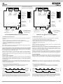 3
3
-
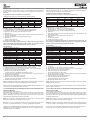 4
4
-
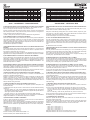 5
5
-
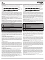 6
6
-
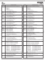 7
7
-
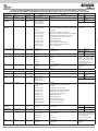 8
8
-
 9
9
-
 10
10
-
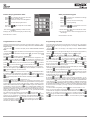 11
11
-
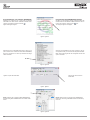 12
12
-
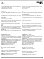 13
13
-
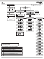 14
14
-
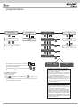 15
15
-
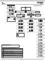 16
16
-
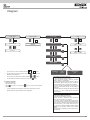 17
17
-
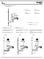 18
18
-
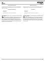 19
19
-
 20
20


in altre lingue
- English: Elvox 69PH
Documenti correlati
Altri documenti
-
Somfy CLAVIER TOUCHE FILAIRE Manuale del proprietario
-
Videotec MAXIMUS MPX Manuale utente
-
SEA Swing Manuale del proprietario
-
-
FAAC 401 MP Manuale del proprietario
-
Videotec ULISSE2 Manuale utente
-
Pulsar AWZ710 Istruzioni per l'uso
-
Vimar 16974.B Istruzioni per l'uso
-
Bticino MHKIT1013 Istruzioni per l'uso
-
Vimar 41002 Manuale utente