Scholtes MIN 32 (L) User Instructions
- Categoria
- Piani cottura
- Tipo
- User Instructions
Questo manuale è adatto anche per

Viale Aristide Merloni 47
60044 Fabriano (AN) Italy
Tel. +39 0732 6611
www.scholtes.com


I
3
Indice
Principio di funzionamento, 4
Istruzioni per l’utente
Installazione, 4
Uso, 4
Manutenzione, 6
Istruzioni per l’installatore
Installazione, 8
Posizionamento, 8
Collegamento elettrico, 8
Assistenza, 10
QUESTO PRODOTTO È STATO CONCEPITO
PER UN IMPIEGO DI TIPO DOMESTICO.
IL COSTRUTTORE DECLINA OGNI
RESPONSABILITÀ NEL CASO DI EVENTUALI
DANNI A COSE O PERSONE DERIVANTI DA
UNA NON CORRETTA INSTALLAZIONE O DA
USO IMPROPRIO, ERRONEO OD ASSURDO.
English
GB
Caro Cliente,
sentitamente La ringraziamo e ci congratuliamo
per la scelta da Lei fatta. Questo nuovo
prodotto, accuratamente progettato e costruito
con materiali di primissima qualità, è stato
accuratamente collaudato per poter soddisfare
tutte le Sue esigenze di una perfetta cottura.
La preghiamo pertanto di leggere e rispettare
le facili istruzioni che Le permetteranno di
raggiungere eccellenti risultati sin dalla prima
utilizzazione. Con questo moderno apparecchio
Le formuliamo i nostri più vivi auguri.
IL COSTRUTTORE
Piano induzione 2 IN
MIN 32 (L)
Italiano
I
Français
FR
Deutsch
DE
Nederlands
NL

I
4
Istruzioni per l’utente
vale a dire che il controllo si spegne, anche attivando più
tasti contemporaneamente.
Accensione di una zona di cottura
Nella modalità di attesa o in quella attiva, una zona di
cottura può venire attivata mediante i tasti Più/Meno, a Meno
che la zona di cottura non si trovi in quel momento nella
programmazione timer (vedi capitolo timer).
Se s’inizia con il tasto “+”, il livello di cottura passa da “0” a
“4”. Se s’inizia con il tasto “-”, il livello di cottura passa da “0”
a “9”.
Spegnimento di una zona di cottura
a) Azionando contemporaneamente il tasto “+” e “-” della
zona di cottura desiderata
b) Selezionando il livello di cottura “0” della zona di cottura
desiderata con il tasto “-”
Se si spegne l’ultima zona di cottura, il controllo commuta nella
modalità OFF dopo 10 s se non ci sono altre attivazioni.
Tutte le zone di cottura vengono spente con effetto immediato
azionando il tasto ON/OFF.
Livelli di cottura e di potenza
I livelli di cottura e di potenza delle zone di cottura vengono
visualizzati tramite un display a 7 segmenti assegnato. Secondo
standard vengono visualizzati i livelli di potenza con i numeri da
“1” a “9”.
Indicatore di calore residuo
Serve a indicare all’utente che il vetro è ad una temperatura
pericolosa in caso di contatto con tutta l’area sovrastante la
zona cottura. La temperatura viene determinata seguendo un
modello matematico e un eventuale calore residuo viene indicato
con una “H” dal corrispondente display a sette segmenti.
Il riscaldamento e il raffreddamento sono calcolati in relazione a:
- Il livello si potenza selezionato (da “0” a “9”);
- Il periodo di attivazione dei relè dopo aver spento la zona
cottura.
Il corrispondente display mostra “H” fino a che la temperatura
della zona non scende al di sotto del livello critico (< 60 °C)
secondo il modello matematico.
Funzione Timer
La funzione Timer può venire utilizzata
come timer per la zona di cottura o come
sveglia indipendente, però mai per
entrambe le funzioni. I due display a 7 segmenti della
rispettiva zona di cottura servono per la visualizzazione
del tempo rimanente in minuti, fino a quando non viene
fatto scattare l’allarme del timer.
Selezione timer
- Per programmare un timer, il touch deve trovarsi nella
modalità di attesa o nella modalità attiva.
- L’azionamento del tasto timer serve per la selezione
della funzione timer per una zona di cottura.
- La segnalazione della programmazione di un timer
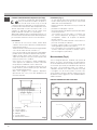
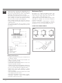
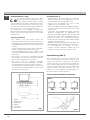
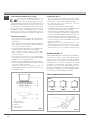
Principio di funzionamento (Fig. 1)
E’ basato sulle proprietà elettromagnetiche della maggior
parte dei recipienti per la cottura. Il circuito elettronico governa
il funzionamento della bobina (induttore) creante un campo
magnetico. Il calore è trasmesso dallo stesso recipiente al cibo.
La cottura avviene come sotto descritto.
- minima dispersione (alto rendimento)
- il ritiro della pentola (basta il solo sollevamento) provoca
automaticamente l’arresto del sistema
- il sistema elettronico permette la massima flessibilità e finezza di
regolazione.
Installazione
Tutte le operazioni relative all’installazione
(allacciamento elettrico) devono essere eseguite da
personale qualificato secondo le norme vigenti.
Per le istruzioni specifiche vedi la parte riservata
alt’installatore.
IMPORTANTE: Questo apparecchio non è adatto per
essere utilizzato da persone (bambini incusi) con ridotte
capacità mentali e fisiche o con mancanza di esperienza
e conoscenza se preventivamente non abbiano ricevuto
adeguate istruzioni per l’uso da persone responsabili per
la loro sicurezza.
I bambini devono essere controllati per assicurarsi
che non giochino con l’apparecchio
Uso
Per prima cosa posizionare la pentola nella zona di
cottura prescelta. La mancanza della pentola display
non consente l’avvio del sistema
Accensione/spegnimento del Touch Control (Fig. 2 e 2a)
L’elettronica Touch Control viene attivata azionando l
tasto ON/OFF e commuta dalla modalità OFF alla
modalità di attesa. A tale scopo occorre azionare il
tasto ON/OFF come tasto unico e per la durata di 1 s. Si
sentirà un breve bip.
Nella modalità di attesa sul display della zona di cottura
viene visualizzato staticamente “0”.
Eventualmente questa visualizzazione può andare in
secondo piano a causa di una segnalazione di calore
residuo oppure di errore.
Se entro il tempo della modalità di attesa (10 s) viene attivata
una zona di cottura, il controllo commuta nella modalità attiva.
Se entro 10 s non viene effettuata nessuna introduzione,
il controllo commuta automaticamente con un breve bip
nella modalità OFF.
Nella modalità attivo o nella modalità di attesa,
l’elettronica può venire commutata in ogni momento nella
modalità OFF azionando il tasto ON/OFF. La funzione di
spegnimento ha sempre priorità durante il funzonamento;

I
5
programmato con dei valori non uguali a 0. Esempio: il timer parte
con il rilascio del tasto Più dopo aver impostato il valore timer “01”.
- Le impostazioni di timer sono prioritarie rispetto alla
delimitazione del tempo di funzionamento in presenza
di impostazioni di livelli alti di cottura.
- Se viene programmata solo una sveglia, il controllo
dapprima rimane nella modalità di attesa (nessun’altra
zona di cottura è attivata). Se non vengono introdotti
altri valori nuovi, il TC si comporta come sopra descritto
e commuta nella modalità di OFF.
Scadere del timer/allarme del timer e conferma
- Gli ultimi 10 s prima dello scadere del timer vengono
visualizzati sul display (count down fino all’allarme).
- Una volta scaduto il tempo impostato di un timer, scatta
l’allarme del timer, la zona di cottura assegnata viene
subito spenta.
- Il display, insieme al led del timer selezionato, lampeggia alternando
il livello di cottura “00” con “H”, in caso di calore residuo.
- La segnalazione dell’allarme dura al massimo 2 minuti,
se l’utente non interviene prima.
- Al termine dei 2 minuti o azionando un tasto qualsiasi, la
segnalazione dell’allarme viene sospesa.
Il segnalino acustico (cicalino) nonchè la spia di controllo
del timer vengono disattivati.
Spegnimento del timer/Modifica delle impostazioni del timer
- E’ possibile modificare il valore impostato del timer,
nella modalità di attesa o attiva, in ogni momento dopo
selezione avvenuta, attivando il tasto Più o Meno.
- E’ possibile spegnere il timer, portandolo sul valore “00”
premendo il tasto Meno o premendo un’unica volta
contemporaneamente i tasti Più o Meno.
Key Lock (sicurezza bambini)
Bloccaggio/attivazione Key Lock
L’azionamento del tasto Key-Lock nella modalità di
attesa o attiva, comporta il bloccaggio della tastiera; il
led Key-Lock “9” si illumina in modo statico.
Il controllo continua a lavorare nella modalità precedentemente
impostata, ma non può più essere comandato da altri tasti,
tranne che dal tasto Key-Lock o dal tasto ON/OFF.
Lo spegnimento con il tasto ON/OFF è possibile anche in
stato di bloccaggio. Il led corrispondente del tasto key lock si
spegne quando si disattiva il touch e la funzione Key-Lock. Il
led è nuovamente attivo in caso di riaccensione (entro 10 s) fino
a quando verrà disattivata azionando nuovamente il tasto Key-
Lock. L’attivazione/disattivazione della funzione Key-Lock nella
modalità di OFF non è possibile.
Sbloccaggio/disattivazione Key Lock
Il nuovo azionamento del tasto Key-Lock nella modalità
di attesa o attiva comporta lo sbloccaggio della tastiera
e lo spegnimento del led Key-Lock assegnato. Tutti i
tasti sensore possono venire nuovamente azionati.
mediante i tasti Più/Meno avviene attraverso il led 8.
Ol led del timer lampeggiante segnala che il valore dei
display a 7 segmenti si riferisce al timer e può venire
modificato. Quando un contatore continua a funzionare
nella modalità OFF, il led del timer s’illumina staticamente.
Ciò indica che il valore raffigurato sui display appartiene
al timer, ma non può venire mmentaneamente modificato
direttamente; a tale scopo occorrerebbe riattivare il
controllo.
- L’azionamento del tasto timer dipende dalle condizioni
di funzionamento precedentemente impostate:
a) La zona di cottura corrispondente al timer è attivata
(livello di cottura > 0): Il timer viene programmato in
riferimento alla zona di cottura; quando si azzera,
spegne automaticamente la zona di cottura; non è
possibile selezionare un contatore indipendente.
Un ulteriore azionamento del tasto timer commuta
direttamente all’impostazione del livello di cottura.
b) La zona di cottura corrispondente al timer è disattivata
(livello di cottura = 0): Il timer viene progtammato
indipendentemente e continua a funzionare anche
nello stato di OFF. Finchè il contatore funziona, non è
possibile attivare la zona di cottura.
Impostazione del valore di timer
- In seguito alla selezione del timer avvenuta, il led
assegnato lampeggia come sopra descritto. Con i tasti
Più/Meno è possibile impostare il tempo di count down
del timer desiderato.
- Iniziando con il tasto Più, il primo valore visualizzato
salta su “01” e aumenta progressivamente da 1 fino a
un massimo di “99” (limite superiore).
- Iniziando con il tasto Meno, il valore visualizzato
sull’indicazione salta su “30” e diminuisce in passi
da 1 fino allo “01” (primo limite inferiore). Al suo
raggiungimento viene emesso un segnale acustico.
Per raggiungere lo “00”, occorre prima rilasciare il tasto
Meno e poi riattivarlo. Azionando ulteriormente il tasto
Meno, la visualizzazione “00” non verrà modificata
(secondo limite inferiore).
- L’impostazione può avvenire anche tramite azionamenti
permanenti dei tasti Più o Meno o tramite azionamenti
singoli (selezionare: azionamento tasto, rilascio,
azionamento, rilascio, ecc.).
- In caso di azionamento permanente del tasto, si
verifica un’accelerazione automatica della velocità di
regolazione, vale a dire che il tempo tra un passo e quello
successivo si riduce, finchè il tasto rimane premuto.
- Se entro 10 s (parametro) il tasto Più o il tasto Meno non
viene nuovamente premuto, dopo aver selezionato il
timer della zona di cottura corrente (il display rimane su
“00”), l’indicazione e l’assegnazione dei tasti Più/Meno
commutano automaticamente alla zona di cottura.
- Quando un timer viene utilizzato come contatore
(sveglia), l’indicazione e l’assegnazione dei tasti non
commutano alla zona di cottura, dato che essa non può
venire attivata.
- Un timer parte in genere con il count down, se quest’ultimo è stato

I
6
Pentolame (Fig. 3)
- se una calamita avvicinata al fondo di un recipiente
rimane attratta questa può già essere una pentola
adatta alla cottura ad induzione.
- preferire pentolame dichiarato anche per cottura ad
induzione.
- pentolame a fondo piatto e spesso.
- una pentola di 20 cm di diametro permette di sfruttare
la massima potenza.
- una pentola più piccola riduce la potenza ma
non causerà dispersione d’energia. E’ comunque
sconsigliabile l’utilizzo di recipienti di diametro
inferiore a 10 cm.
- recipienti inox con fondo multistrato o inox ferritico se
precisato sul fondo: per induction
- recipienti in ghisa meglio se con fondo smaltato per
evitare graffiature al piano vetroceramico
- sono sconsigliati e non convengono recipienti in vetro,
ceramica, terracotta recipienti in alluminio, rame o
inox non magnetico (austenitico).
Manutenzione (Fig. 4)
Tracce di fogli di alluminio, residui di cibo spruzzi di
grasso, zucchero o cibi fortemente saccariferi devono
essere immediatamente rimossi dal piano di cottura con
un raschietto per evitare possibili danni alla superficie
del piano. Successivamente pulire con SIDOL o
STANFIX e carta da cucina, indi risciacquare con acqua
e asciugare con uno straccio pulito. In nessun caso
usare spugne o strofinacci abrasivi; evitare anche l’uso
di detersivi chimici aggressivi come FORNOSPRAY o
SMACCHIATORI.
NON UTILIZZARE PULITORI A VAPORE
Fig.2
NO NO SI
Fig.3
Funzione mantenimento della temperatura (Lo Temp)
La funzione mantenimento della temperatura
serve per mantenere riscaldati i cibi pronti su
una zona di cottura. A tale scopo, la zona di
cottura prescelta viene alimentata con una potenza bassa.
La funzione di mantenimento della temperatura viene
attivata impostando il livello di cottura tra 0 e 1; su
entrambe le indicazioni delle zone di cottura viene
quindi visualizzato il simbolo “Lo” (vedi sopra).
Abbassando i gradi di cottura con il tasto Meno premuto, ci si
ferma al livello di cottura di mantenimento della temperatura;
per commutare a livello 0 occorre un nuovo azionamento.
Precauzioni
- al verificarsi di una anche minima frattura della
superficie vetroceramica disinserire immediatamente
l’alimentazione elettrica
-
durante il funzionamento allontanare materiale magnetizzabile
come carte di credito, dischetti, calcolatrici, ecc.
- non usare mai fogli di carta alluminata o appoggiare
prodotti avvolti con alluminio direttamente sul piano
- oggetti metallici quali coltelli, forchette, cucchiai e
coperchi non devono essere posti sulla superficie del
piano per evitare che si scaldino
- nella cottura con recipienti a fondo antiaderente,
senza apporto di condimento, limitare l’eventuale
tempo di preriscaldamento a uno o due minuti.
- la cottura di alimenti con tendenza ad attaccare sul
fondo iniziare a potenza minima per poi aumentare
mescolando frequentemente.
- dopo l’uso spegnere con l’apposito dispositivo
(decremento sino a “D”) e non fare affidamento sul
rilevatore di pentole.
Fig.1
1 - recipiente
2 - corrente indotta
3 - campo magnetico
4 - induttore
5 - circuito elettrico
6 - alimentazione elettrica

I
7
2
1
7
8 8 9
5
3b
4 6 5
3a
4 2 1
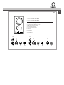
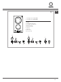
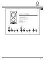
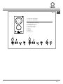
Fig.4
1. zona cottura Ø 160/1400W
2. zona cottura Ø 200/2300W
1. accensione/spegnimento
2. sicurezza bambini (key lock)
3. indicazione zona cottura
4. incremento potenza
5. decremento potenza
6. Timer/a
7. Timer/b
8. Led timer
9. Led key lock

I
8
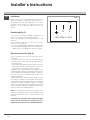
Istruzioni per l’installatore
Installazione
Le presenti istruzioni sono rivolte all’installatore
qualificato quale guida all’installazione, regolazione
e manutenzione secondo le leggi e le normative in
vigore. Gli interventi devono sempre essere effettuati
ad apparecchiatura disinserita elettricamente.
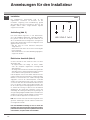
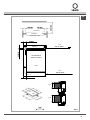
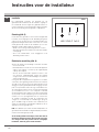
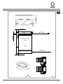
Posizionamento (Fig. 5)
L’apparecchio è previsto per essere incassato in un
piano come illustrato nell’apposita figura. Predisporre su
tutto il perimetro delpiano il sigillante a corredo.
E’ sconsigliabile l’installazione sopra un forno
contrariamente accertarsi che:
- il forno sia munito di un efficace sistema di
raffreddamento.
- che non avvenga in nessun caso passaggio di aria
calda dal forno verso il piano.
- prevedere passaggi d’aria come indicato in figura.
Collegamento elettrico (Fig. 6)
Prima di effettuare l’allacciamento elettrico accertarsi che:
- le caratteristiche dell’impianto siano tali dasoddisfare
quanto indicato sulla targa matricola applicata sul fondo
del piano;
- che l’impianto siamunito di un efficace collegamento di
terra secondo le norme e le disposizioni di legge in vigore.
La messa a terra è obbligatoria a termini di legge.
Nel caso che l’apparecchiatura non sia munita di cavo e/o di
relativa spina utilizzare materiale idoneo per l’assorbimento
indicato in targa matricola e per la temperatura di lavoro. Il
cavo in nessun punto dovrà raggiungere una temperatura
superiore di 50°C a quella ambiente.
Per il collegamento diretto alla rete è necessario interporre
un interruttore omnipolare dimensionato per il carico di targa
che assicuri la sconnessione della rete con una distanza
di apertura dei contatti che consenta la disconnessione
completa nelle condizioni della categoria di sovratensione
III, conformemente alle regole di installazione (il cavo di
terra giallo/verde non deve essere interrotto).
La presa o l’interruttore omnipolare devono essere facilmente
reggiungibili con l’apparecchiatura installata.
N.B.: - Il costruttore declina ogni responsabilità nel caso
che quanto sopra e le usuali norme antirfortunistiche non
vengano rispettate.
Se il cavo dialimentazione è danneggiato, esso deve
essere sostituito dal costruttore o dal suo servizio
assistenza tecnica o comunque da una persona con
qualifica similare, in modo da prevenire ogni rischio.
LN
230V
~
H05 V2V2–F 3x2.5
Fig.6

I
9
INDUZIONEINDUCTIONINDUCTION)NDUKTION
INDUCCIØNINDUCTIEINDUÎÍO
aria - air - air - Luft - aire - lucht - ar
100 cm
2
MIN.
induzione - induction - induction - Induktion
- inducción - inductie - indução
aria - air - air - Luft - aire - lucht - ar
100 cm
2
MIN.
ZONA FORNO O ARMADIETTO
OVEN ZONE OR CUPBOARD
ZONE FOUR OU PLACARD
OFENBEREICH ODER SCHRANK
ZONA HORNO O ARMARIO
OVENRUIMTE OF KASTJE
ZONA DO FORNO OU ARMÁRIO
LATOSIDECÙTÏLADOZIJKANTSEITE
50 MIN.
50 MIN.
20 MIN.
(2 x 500)
40 mm.
30 mm.
303
520
Fig.5
Fronte
Induzione
ZONA FORNO O
ARMADIETTO
Induzione
Lato
Aria
Aria

I
10
La Casa costruttrice declina ogni responsabilità per le possibili inesattezze contenute nel presente opuscolo, imputabili
ad errori di stampa o di trascrizione. Si riserva il diritto di apportare ai propri prodotti quelle modifiche che ritiene
necessarie o utili, senza pregiudicare le carratteristiche essenziali.
Assistenza
Prima di contattare il Servizio di Assistenza Tecnica:
1. Verificare se non è possibile eliminare da soli i guasti.
2.
Riavviare il prodotto per accertarsi che l’inconveniente
sia stato ovviato. Se il risultato è negativo, disinserire
nuovamente il prodotto e ripetere l’operazione dopo un’ora.
3. Se il problema persiste, contattare il Servizio
Assistenza Tecnica.
Comunicare:
• iltipodiguasto,
• ilmodello,
• IlnumeroService(lacifrachesitrovadopolaparola
SERVICE sulla targhetta matricola posta sul retro del
prodotto)
• ilproprioindirizzocompleto,
• ilproprionumeroepressotelefonico.
Queste ultime informazioni si trovano sulla targhetta
caratteristiche posta sull’apparecchio.
Assistenza Attiva 7 giorni su 7
In caso di necessità d’intervento chiamate il Numero
Unico Nazionale 199.199.199*. Un operatore sarà a
completa disposizione per fissare un appuntamento
con il Centro Assistenza Tecnico Autorizzato più vicino
al luogo da cui si chiama. È attivo 7 giorni su 7, sabato
e domenica compresi, e non lascia mai inascoltata una
richiesta.
* Il costo della telefonata è di 14,25 centesimi di Euro al
minuto (iva inclusa) dal lunedì al venerdì dalle ore 8.00
alle ore 18.00, ed il sabato dalle ore
8.00 alle ore 13.00; e di 5,58 centesimi di Euro al
minuto (iva inclusa) dal lunedì al venerdì dalle 18.00
alle 08.00, ed il sabato dalle 13.00 alle 08.00 e i giorni
festivi, per chi chiama da telefono fisso. Per chi chiama
da cellulare il costo è legato all’operatore telefonico
utilizzato. Le suddette tariffe potrebbero essere
soggette a variazione da parte dell’operatore telefonico
utilizzato, per maggiori informazioni consultare il sito
www.indesitcompany.com.

11
GB
Index
Operating principle, 12
User’s instructions
Installation, 12
Use, 12
Maintenance, 14
Installater’s instructions
Installation, 16
Positioning, 16
Electrical connection, 16
Assistance, 18
THIS APPLIANCE IS CONCEIVED FOR
DOMESTIC USE ONLY. THE MANUFACTURER
SHALL NOT IN ANY WAY BE HELD
RESPONSIBLE FOR WHATEVER INJURIES
OR DAMAGES ARE CAUSED BY INCORRECT
INSTALLATION OR BY UNSUITABLE, WRONG
OR ABSURD USE.
English
GB
Dear customer,
We thank you and con-gratulate you on your
choice. This new carefully de-signed product,
manu-factured with the highest quality materials,
has been carefully tested to satisfy all your
cooking demands. We would therefore request
you to read and follow these easy instructions
which will allow you to obtain ex-cellent results
right from the start. May we wish you all the
very best with your modern appliance!
THE MANUFACTURER
Induction hob 2 IN
MIN 32 (L)
Italiano
I
Français
FR
Deutsch
DE
Nederlands
NL

12
GB
User’s Instructions
If starting with the “+” button, the cooking level changes
from “0” to “4”. If starting with the “-“ button, the cooking
level changes from “0” to “9”.
Switching off a cooking zone
a) Pressing the “+” and “-” buttons of the desired cooking
zone at the same time
b) Selecting cooking level “0” of the desired cooking
zone with the “-” button
If the last cooking zone is switched off, the control
switches to the OFF mode after 10 sec. if nothing else
is switched on.
All cooking zones are switched off immediately by
pressing the ON/OFF button.
Cooking and power levels
The cooking and power levels of the cooking zones
are shown on the display with 7 allotted segments.
In accordance with standards, the power levels are
displayed with numbers from “1” to “9”.
Residual heat indicator
Indicates to the user that the glass is at a dangerous
temperature if in contact with the area over the cooking
zone. The temperature is determined by means of a
mathematical model and possible residual heat is indicated
by “H” on the corresponding 7 segment display.
Heating and cooling are calculated based on:
- The selected power level (from “0” to “9”);
- The relay activation time after the cooking zone has
been switched off.
The corresponding display shows “H” until the zone
temperature drops below the critical level (< 60 °C)
according to the mathematical model.
Timer function
The Timer function can be used as a
cooking zone timer or independent
alarm but never for both functions. The
two 7 segment displays of the respective cooking zones
are used to view the remaining time in minutes up until
the timer alarm is activated.
Timer selection
- To program a timer, the touch control must be in the
Standby or On mode.
- The timer button is pressed in order to select a timer
function for the cooking zone.
- LED 8 signals the timer programming by means of the
+/- buttons. The flashing timer LED signals that the 7
segment display value refers to the timer and can be
modified. When a timer continues to function in the
OFF mode, the timer LED remains on. This indicates
that the value on the display is related to the timer, but
cannot be directly modified at that particular moment;
to do so, the control must be reactivated.
- The activation of the timer button depends on the
Operating Principle (Fig. 1)
It expIoits the eIectromagnetic properties of most cooking vessels.
The coil (inductor) which produces the eIectromagnetic
fieId is operated and controlled by the eIectronic circuit.
The heat is transmitted to food by the cooking vesseI itself.
The cooking process takes pIaceas described beIow.
- Ioss of heat is minimum (high efficiency)
- the systemstops automatically when the vesseIis
removed or even just lifted from the hob
- the eIectronic circuit guarantees maximum flexibility
and fine adjustments.
Installation
AlI operations relative to installation (electric connection)
should be carried out by skilled personnel inconformity
with the rules in force.
As for the specific instruction see part pertaining to
installer.
IMPORTANT: This apparatus is not suitable for use by
persons (children included) with reduced mental and
physical capacity or with lack of experience and knowledge
unless having previously received suitable training for its
use by persons responsible for their safety.
It must be ensured that children do not play with the apparatus
Use
First pIace the pan in the chosen cooking zone. If the pan
is not present the system can not be switched on.
On/off of the Touch Control (Fig. 2 e 2a)
The electronic Touch Control is activated by eans
of the ON/OFF button and switches from the OFF
mode to the Standby mode. To do so it is necessary
to press the ON/OFF button for 1 second. A short Beep
will be heard. When in standby, “0” is displayed on the
display of the cooking zone. This display may go into
background due to a residual heat or error signal.
If a cooking zone is activated during the standby time
(10 sec.), the control switches over to the On mode.
If no introduction is made within the 10 sec., the control
automatically switches to OFF with a short beep.
The electronics can be switched to the OFF mode at
any time during the ON mode or the Standby mode by
pressing the ON/OFF button. The Off function has priority
when operating, meaning that the control switches off
even by activating several buttons at the same time.
Switching on a cooking zone
When in the Standby or On mode, a cooking zone can
be switched on by means of the Plus/Minus button, as
long as the cooking zone is not in the timer programming
mode at that moment (see Timer chapter).

13
GB
switched off.
- The display and the selected timer LED flash
alternating the cooking level from “00” to “H”, if there
is residual heat.
- The warning alarm lasts for at least 2 minutes if the
user does not switch it off before.
- The alarm signal switches off after the 2 minutes is up
or if any button is pushed. The buzzer and the timer
control light are switched off.
Timer off /Modification of the timer setting
- The timer settings can be modified in the Standby
or On mode at any time after the selection has been
made by pressing the Plus or Minus buttons.
- The timer can be switched off, setting it to value “00”,
by pressing the Minus button or by pressing the Plus
and Minus buttons together.
Key Lock (child safety)
Locking/unlocking of the Key Lock
The keypad is blocked when the Key Lock
button is pressed in the Standby or On mode;
the Key-Lock LED “9” lights permanently.
The control continues to operate in the previously set
mode but can no longer be controlled by other buttons,
except by the Key-Lock button or the ON/OFF button.
Switching off with the ON/OFF button is also possible
when locked. The Key-lock button LED switches off
when the Touch control and Key-Lock function are
switched off. The LED lights again if reactivated (within
10 sec.) until it is deactivated by pressing the Key-Lock
button once again. The activation/deactivation of the
Key-Lock function is not possible in the OFF mode.
Unlocking/deactivation of the Key Lock
The keypad is unlocked and the Key-Lock LED is
switched off when the Key-Lock button is pressed
again in the Standby or On mode. All sensor buttons
can once again be activated.
Keep- warm function (Lo Temp)
The keep-warm function serves to keep the
food on a cooking zone warm. To do so, the
selected cooking zone is supplied with a
lower power. The keep-warm function is activated by
setting the cooking level between 0 and 1. The “Lo”
symbol is thereby indicated on both cooking zone
displays (see above).
Lowering the cooking temperature with the “-“ button
pressed, the temperature stops on the keep-warm
cooking level. Push the button again to switch to “0”.
Precautions
- in case you detect a crack, however small, in the hob
surface, immediately disconnect the power supply
conditions of the previously set function:
a) The cooking zone corresponding to the timer is
on (cooking level > 0): The timer is programmed
in reference to the cooking zone; the cooking
zone automatically switches off when reset;
an independent timer cannot be selected. The
cooking level setting is accessed when the timer
button is pressed again.
b) The cooking zone corresponding to the timer is
off (cooking level = 0): The timer is independently
programmed and continues to function even in
OFF. The cooking zone cannot be activated until
the timer is functioning.
Setting of the Timer value
- Following the selection of the time, the related LED
flashes as described above. The countdown time of the
desired timer can be set by means of the +/- buttons.
- Starting with the plus button, the first value displayed
is “01” and progressively increases from 1 to a
maximum value of “99” (upper limit).
- Starting with the minus button, the value displayed on
the indication is “30” and diminishes to “01” (first lower
limit). When this value is reached, an acoustic signal
is emitted. By pressing the minus button again, the
display “00” will not be modified (second lower limit).
- Setting can be performed by permanently pressing
the plus or minus buttons or by intermittently pressing
them (selection: press button, release, press button,
release, etc).
- If the button is permanently pressed, the regulation
speed automatically accelerates, meaning that the
time between one step and the next is reduced, until
the button is released.
- If the Plus or Minus buttons are not pressed within
10 sec. (parameter), after having selected the timer
of the current cooking zone (the display remains on
“00”), the indication and allocation of the +/- buttons
automatically switch to the cooking zone.
- When a timer is used as an alarm, the indication
and allocation of the buttons does not switch to the
cooking zone, being that this cannot be activated.
- The timer normally starts in countdown, if programmed
with two values that are not 0. For example: the timer
starts when the Plus button is released after the timer
value has been set at “01”.
- The timer settings have priority over the delimitation of
the operating time if high cooking levels have been set.
- If only one alarm has been programmed, the control remains
at first in the standby mode (no other cooking zone is on).
If no other new values are introduced, the TC behaves as
described above and switches to the OFF mode.
Timer laps/timer alarm and confirmation
- The last 10 sec. before the timer lapses are displayed
(countdown up to alarm).
- Once the set time of the timer has lapsed, the timer
alarm is activated and the assigned cooking zone is

14
GB
Maintenace (Fig. 4)
By means of a scraper immediately remove any
alluminium foil bits, food spills, grease splashes, sugar
marks and other high sugarcontent food from the
surface in order to avoid damaging the hob.
Subsequently clean the surface with some paper towel
and SIDOL or STANFIX, rinse with water and dry by
means of a clean cloth.
Under no circumstance should sponges or abrasive
cloths be used; also avoid using aggressive chemical
detergents such as oven sprays and spot removers.
DO NOT USE STEAM CLEANERS
Fig.2
NO NO YES
Fig.3
- when the hob is in use keep all magnetizable objects
away (credit cards, floppy disks, calculators and so on)
- do not use any alluminium foil or place any foodstuffs
wrapped in alluminium foil directly on the hob
- do not place any metal objects such as knives, forks,
spoons and lids on the hob surface as they will heat up
- when cooking in a nonstick pan without seasoning,
do not exceed 1-2 minutes’ pre-heating time
- when cooking food that may easily stick, start at a
low power output level and then slowly increase while
regularly stirring.
- after cooking is finished, switch off using the control
provided (turn down to “0”), and do not rely on the
pan sensor.
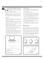
Fig.1
1 - vessel
2 - induced current
3 - magnetic field
4 - inductor
5 - electronic circuit
6 - power supply
Cooking vessels (Fig. 3)
- a magnet attracting vessel may be a suitable vessel
for induction cooking
- prefer vessels which are especially declared to be
suitable for induction cooking
- flat and thickbottomed vessels
- a vessel with a 20 centimeter diameter ensures the
maximum exploitation of power
- a smaller vessel reduces power exploitation, but does not
cause any energy loss We would anyhow not recommend
the use of vessels with diameters smaller than 10 cm.
- stainless-steel vessels with multilayer or ferritic
stainless-steel bottoms when specifically suited for
induction cooking
- cast iron preferably enamel bottomed vessels to avoid
scratching the pyroceram surface
- we do not recommend the use of any glass, ceramic,
earthenware, alluminium, copper or non-magnetic
(austenitic) stainless-steel vessels.

15
GB
2
1
7
8 8 9
5
3b
4 6 5
3a
4 2 1
Fig.4
1. cooking zone Ø 160/1400W
2. cooking zone Ø 200/2300W
1. On/Off
2. Child safety (key lock)
3. Cooking zone indication
4. Power increase
5. Power Decrease
6. Timer/a
7. Timer/b
8. Timer Led
9. Key lock Led

16
GB
Installer’s Instructions
Installation
These Instructions are for the qualified technician, as a
guide to installation, adjustment and maintenance,
according to the Iaws and standards in force. These
operations must aIways be carried out when the
appliance has been disconnected from the eIectric
system.
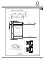
Positioning (Fig. 5)
The fixture is especially designed for fitting into a
worktop as shown in the corresponding figure.
PIace the supplied sealing agent along the hob
perimeter.
Do not install the hob over an oven; incase you do,
make sure of the following:
- the oven is equipped with an appopriate cooling system
- there isno warm-air Ieakage from the oven to wards the hob
- suitabIe air-inIets are provided as shown in the figure.
Electrical connection (Fig. 6)
Prior to carrying out the eIectrical connection, please
ensure that:
- the plant characteristics are such as to follow what is
indicated on the matrix plate placed atthe bottom of
the working area;
- that the plant is fitted with an efficient earth connection,
folIowing the standards and law provisions in force. The
earth connection is compulsory interrns of the law.
Should there beno cable and/or plug on the equipment, use
suitable absorption material for the working temperature as
well, as indicated on the matrix plate. Under no circumstance
must the cable reach a temperature above 50°C of the
ambient temnerature.
If connecting directly to the mains power supply, fita multi-
poie switch ofa suitable size for the rated capacity with a
clearance distance which completely disconnects the power
line under over voltage category III conditions, consistently
with the rules of installation (the yellow/green earth wir must
not be interrupted). The plug or omnipolar switch must be
easily reached on the installed equipment.
N.B.: The manufacturers decline any responsibility in the
event of non-compliance with what is described above and
the accident prevention norms not being respected and
followed.
To avoid all risk, if the power cable becomes damaged,
it must only be replaced by the manufacturer, by an
authorised service centre, or by a qualified electrician.
LN
230V
~
H05 V2V2–F 3x2.5
Fig.6

17
GB
INDUZIONEINDUCTIONINDUCTION)NDUKTION
INDUCCIØNINDUCTIEINDUÎÍO
aria - air - air - Luft - aire - lucht - ar
100 cm
2
MIN.
induzione - induction - induction - Induktion
- inducción - inductie - indução
aria - air - air - Luft - aire - lucht - ar
100 cm
2
MIN.
ZONA FORNO O ARMADIETTO
OVEN ZONE OR CUPBOARD
ZONE FOUR OU PLACARD
OFENBEREICH ODER SCHRANK
ZONA HORNO O ARMARIO
OVENRUIMTE OF KASTJE
ZONA DO FORNO OU ARMÁRIO
LATOSIDECÙTÏLADOZIJKANTSEITE
50 MIN.
50 MIN.
20 MIN.
(2 x 500)
40 mm.
30 mm.
303
520
Fig.5
Front
Induction
OVEN ZONE OR
CUPBOARD
Induction
Side
Air
Air

18
GB
The manufacturer declines all responsibility for possible inaccuracies contained in this pamphlet, due to printing or
copying errors. We reserve the right to make on our own products those changes to be considered necessary or useful,
without jeopardizing the essential characteristics.
Assistance
Before contacting After-Sales Service:
1. See if you can solve the problem yourself.
2. Switch the appliance on again to see if the problem
has been solved. if it has not, disconnect the
appliance from the power supply and wait for about
an hour before switching on again.
3. If the problem persists after this course of action,
contact After-Sales Service.
Specify:
• thenatureofthefault,
• themodel
• the service number (the number after the word
SERVICE on the rating plate on the rear of the
appliance)
• yourfulladdress,
• yourtelephonenumberandareacode.
Never call on unauthorized technicians and always
refuse to purchase non-original spare parts.

19
FR
Index
Principe de fonctionnement, 20
Notice d’emploi
Installation, 20
Emploi, 20
Entretien, 22
Modalités d’installation
Installation, 24
Positionnement, 24
Branchement électrique, 24
Assistance, 26
CE PRODUIT EST CONÇU EXCLUSIVEMENT
POUR USAGE DOMESTIQUE. LE
CONSTRUCTEUR DÉCLINE TOUTE
RESPONSABILITÉ POUR DOMMAGES
ET BLESSURES CAUSÉES PAR UNE
INSTALLATION INCORRECTE OU PAR UN
USAGE IMPROPRE, ERRONÉ OU ABSURDE.
English
GB
Chère cliente, Cher client,
merci et sincères félicitations pour le choix que
vous avez fait. Ce nouveau produit, développé
avec soin et fabriqué avec des matières de
toute première qualité, a été soigneusement
rodé pour satisfaire toutes Vos exigences d’une
cuisson parfaite. Veuillez lire attentivement les
instructions simples portées sur cette notice
qui vous permettront d’obtenir d’excellents
résultats dès la première utilisation. Nous vous
souhaitons une entière et pleine satisfac-tion
quant à l’utilisation de cet appareil moderne.
LE CONSTRUCTEUR
Table à induction 2 IN
MIN 32 (L)
Italiano
I
Français
FR
Deutsch
DE
Nederlands
NL

20
FR
Instructions pour l’usager
Mise en marche d’un foyer
En mode d’attente ou en mode actif, un foyer peut être enclenché à
l’aide des touches Plus/Moins, à moins que la zone de cuisson ne
se trouve en programmation minuterie à ce moment-là (voir chapitre
minuterie).
Si on commence avec la touche “+”, le niveau de cuisson passe
de “0 » à « 4 ». Si on commende avec la touche “-”, le niveau de
cuisson passe de “0 » à « 9 ».
Arrêt d’un foyer
a) En actionnant simultanément la touche “+” et “-” du
foyer voulu
b) en sélectionnant le niveau de cuisson « 0 » du foyer
voulu à l’aide de la touche “-”
Si on éteint le dernier foyer, le contrôle commute en mode OFF
après 10 sec s’il n’y a pas d’autres commandes.
Tous les foyers s’éteignent immédiatement en enclenchant la
touche ON/OFF.
Niveaux de cuisson et de puissance
Les niveaux de cuisson et de puissance des foyers de cuisson
sont affichés à l’aide d’un afficheur spécial à 7 segments. Selon
les standard, les niveaux de puissance sont affichés avec des
numéros de “1” à “9”.
Indicateur de chaleur résiduelle
Sert à indiquer à l’utilisateur que le verre est à une température
dangereuse en cas de contact avec toute la surface au-dessus
du foyer. La température est définie en suivant un modèle
mathématique et une chaleur résiduelle éventuelle est indiquée
par un « H » sur l’afficheur correspondant à sept segments.
Le chauffage et le refroidissement sont calculés en fonction :
- du niveau de puissance sélectionné (de “0” à “9”).
- la période d’enclenchement des relais après avoir éteint le foyer.
L’afficheur correspondant affiche «H» jusqu’à ce que la
température du foyer descende sous le niveau critique (< 60
°C) selon le modèle mathématique.
Fonction minuterie
La fonction minuterie peut être utilisée
comme minuterie pour le foyer ou comme
réveil indépendant mais jamais pour les
deux fonctions. Les deux afficheurs à 7 segments du foyer
respectif servent à afficher le temps restant en minutes,
jusqu’à ce que retentisse l’alarme de la minuterie.
Sélection de la minuterie
- Pour programmer la minuterie, la touche doit se
trouver en mode d’attente ou en mode actif.
- L’enclenchement de la touche minuterie sert à
sélectionner la fonction minuterie pour un foyer de
cuisson.
- La programmation d’une minuterie par les touches
Plus/Moins est signalée par le voyant 8. Le voyant
clignotant de la minuterie signale que la valeur des
afficheurs à 7 segments se rapporte à la minuterie et
peut être modifiée. Quand un compteur continue à
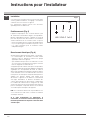
Principe de fonctionnement (Fig. 1)
Il se base sur les propriétés électromagnétiques de la plupart
des récipients de cuisson. Le circuit électronique contrale le
fonctionnement de la bobine (inducteur) qui crée un champ
magnétique. C’est le récipient de cuisson méme qui transmet la
chaleur aux aliments. La cuisson a lieu comme décrit cidessous.
- déperdition minimale (haut rendement)
- le système s’arréte automatiquement si l’on retire ou seulement
soulève la casserole
- le système électronique garantit le maximum de flexibilité et de
précision de réglage.
Installation
Toutes les opérations rélatives à l’installation
(raccordement électrique) doivent ètre faites par un
personnel qualifié, en conformité avec les normes en
vigueur. En ce qui concerne les instructions spécifiques
voir la partie réservée à l’installateur.
IMPORTANT: L’emploi de cet appareil ne doit pas ètre
confié à des personnes (enfants compris) dontlescapacités
mentales et physiques sontréduites ou qui manquent
d’expérience et deconnaissance, si elles n’oni pas reçu
aupréalable les instructions d’emploi adéquates concernant
leur sécurité de la part de personnes responsables.
Lesenfants doivent èire surveillésafin d’èire sùr
qu’ils ne jouent pasavec l’appareil.
Utilisation
PIacer d’abord la marmite sur la zone de cuisson choisie.
L’absencede la marmite
empéche le systèmede
démarrer.
Mise en marche/ arrêt du Touch Control (Fig. 2 et 2a)
L’électronique Touch Control s’enclenche en actionnant la
touche ON/OFF et en commutant le mode OFF en mode
d’attente. Pour ce faire, il faut enclencher la touche ON/
OFF en touche unique durant 1 sec. On percevra un bip rapide.
En mode d’attente, l’afficheur du foyer de cuisson affiche
statiquement “0”.
Eventuellement, cet affichage peut passer au second plan à
cause d’un signalement de chaleur résiduelle ou d’erreur.
Si un foyer est enclenché durant le délai de mode
d’attente (10 sec), le contrôle passe en mode actif.
Si aucune commande n’advient dans les 10 sec, le
contrôle commute automatiquement en mode OFF
avec un bip rapide.
En mode actif ou en mode d’attente, l’électronique peut
être commutée à tout moment en mode OFF à l’aide
de la touche ON/OFF. La fonction d’arrêt a toujours
priorité durant le fonctionnement, ce qui signifie que
le contrôle s’éteint même en enclenchant plusieurs
touches simultanément.
La pagina sta caricando ...
La pagina sta caricando ...
La pagina sta caricando ...
La pagina sta caricando ...
La pagina sta caricando ...
La pagina sta caricando ...
La pagina sta caricando ...
La pagina sta caricando ...
La pagina sta caricando ...
La pagina sta caricando ...
La pagina sta caricando ...
La pagina sta caricando ...
La pagina sta caricando ...
La pagina sta caricando ...
La pagina sta caricando ...
La pagina sta caricando ...
La pagina sta caricando ...
La pagina sta caricando ...
La pagina sta caricando ...
La pagina sta caricando ...
La pagina sta caricando ...
La pagina sta caricando ...
La pagina sta caricando ...
La pagina sta caricando ...
La pagina sta caricando ...
La pagina sta caricando ...
La pagina sta caricando ...
La pagina sta caricando ...
-
 1
1
-
 2
2
-
 3
3
-
 4
4
-
 5
5
-
 6
6
-
 7
7
-
 8
8
-
 9
9
-
 10
10
-
 11
11
-
 12
12
-
 13
13
-
 14
14
-
 15
15
-
 16
16
-
 17
17
-
 18
18
-
 19
19
-
 20
20
-
 21
21
-
 22
22
-
 23
23
-
 24
24
-
 25
25
-
 26
26
-
 27
27
-
 28
28
-
 29
29
-
 30
30
-
 31
31
-
 32
32
-
 33
33
-
 34
34
-
 35
35
-
 36
36
-
 37
37
-
 38
38
-
 39
39
-
 40
40
-
 41
41
-
 42
42
-
 43
43
-
 44
44
-
 45
45
-
 46
46
-
 47
47
-
 48
48


Scholtes MIN 32 (L) User Instructions
- Categoria
- Piani cottura
- Tipo
- User Instructions
- Questo manuale è adatto anche per
in altre lingue
- English: Scholtes MIN 32 (L)
- français: Scholtes MIN 32 (L)
- Deutsch: Scholtes MIN 32 (L)
- Nederlands: Scholtes MIN 32 (L)
Altri documenti
-
Baumatic BHIW400SS Manuale utente
-
Baumatic BHI400SS - 33801365 Manuale utente
-
Candy CDI32/1B Manuale utente
-
ROSIERES RDVI342/1B Manuale utente
-
Baumatic BHTP400SS Manuale utente
-
Nodor IPS 37 specificazione
-
-
Nodor IB 36 B1 Manuale utente
-
Whirlpool VIX 644 CE M IT Guida utente
-
Cata IB 5004 BK Manuale utente