
USER MANUAL
MANUALE UTENTE
MINIECLTR
MINIECL
EN - IT
MINI LED ELLIPSOIDAL
Optics
(not included)
MINIECLIPSETR
• MINIECLIPSETRTU
• MINIECLIPSETRDY
MINIECLIPSETRL
• MINIECLIPSETRL19
• MINIECLIPSETRL26
• MINIECLIPSETRL36
• MINIECLIPSETRL50
Optics
(not included)
MINIECLIPSE
• MINIECLIPSETU
• MINIECLIPSEDY
MINIECLIPSEL
• MINIECLIPSEL19
• MINIECLIPSEL26
• MINIECLIPSEL36
• MINIECLIPSEL50

All rights reserved by Music & Lights S.r.l. No part of this instruction manual may be
reproduced in any form or by any means for any commercial use.
In order to improve the quality of products, Music&Lights S.r.l. reserves the right to modify the
characteristics stated in this instruction manual at any time and without prior notice.
All revisions and updates are available in the ‘manuals’ section on site www.musiclights.it
REV.001-07/15

1
MINIECL - MINIECLTR
Packing content
• MINIECL
• Power cable
• User manual
TABLE OF CONTENTS
Safety
General instructionsGeneral instructions
Warnings and installation precautionsWarnings and installation precautions
1 Technical drawing
1. 1 The congurations MINIECL/TR1. 1 The congurations MINIECL/TR
1. 2 Operating elements and connections1. 2 Operating elements and connections
2 Installation
2. 1 Mounting2. 1 Mounting
3 Functions and settings
3. 1 Operation3. 1 Operation
4 Maintenance
4. 1 Maintenance and cleaning the unit4. 1 Maintenance and cleaning the unit
4. 2 Trouble shooting4. 2 Trouble shooting
2
2
3
4
5
6
7
7
7

MINIECL - MINIECLTR
2
SAFETY
General instruction
• The products referred to in this manual conform to the European Community Directives and are there-
fore marked with .
• The unit is supplied with hazardous network voltage (230V~). Leave servicing to skilled personnel only.
Never make any modications on the unit not described in this instruction manual, otherwise you will
risk an electric shock.
• Connection must be made to a power supply system tted with ecient earthing (Class I appliance ac-
cording to standard EN 60598-1). It is, moreover, recommended to protect the supply lines of the units
from indirect contact and/or shorting to earth by using appropriately sized residual current devices.
• The connection to the main network of electric distribution must be carried out by a qualied electrical
installer. Check that the main frequency and voltage correspond to those for which the unit is designed
as given on the electrical data label.
• This unit is not for home use, only professional applications.
• Never use the xture under the following conditions:
- in places subject to vibrations or bumps;
- in places with a temperature of over 45 °C.
• Make certain that no inammable liquids, water or metal objects enter the xture.
• Do not dismantle or modify the xture.
• All work must always be carried out by qualied technical personnel. Contact the nearest sales point for
an inspection or contact the manufacturer directly.
• If the unit is to be put out of operation denitively, take it to a local recycling
plant for a disposal which is not harmful to the environment.
Warnings and installation precautions
• If this device will be operated in any way dierent to the one described in this manual, it may suer
damage and the guarantee becomes void. Furthermore, any other operation may lead to dangers like
short circuit, burns, electric shock, etc.
• Before starting any maintenance work or cleaning the projector, cut o power from the main supply.
• Always additionally secure the projector with the safety rope. When carrying out any work, always com-
ply scrupulously with all the regulations (particularly regarding safety) currently in force in the country
in which the xture’s being used.
• Install the xture in a well ventilated place.
• Keep any inammable material at a safe distance from the xture.
• Shields, lenses or ultraviolet screens shall be changed if they have become damaged to such an extent
that their eectiveness is impaired.
• The lamp (LED) shall be changed if it has become damaged or thermally deformed.
• Never look directly at the light beam. Please note that fast changes in lighting, e. g. ashing light, may
trigger epileptic seizures in photosensitive persons or persons with epilepsy.
• Do not touch the product’s housing when operating because it may be very hot.
• This product was designed and built strictly for the use indicated in this documentation. Any other use,
not expressly indicated here, could compromise the good condition/operation of the product and/or
be a source of danger.
• We decline any liability deriving from improper use of the product.
WARNING! Before carrying out any operations with the unit, carefully read this instruction
manual and keep it with cure for future reference. It contains important information about
the installation, usage and maintenance of the unit.

3
MINIECL - MINIECLTR
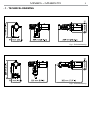
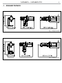
- 1 - TECHNICAL DRAWING
Fig.1 - Technical drawing
Fig.2 - Technical drawing

MINIECL - MINIECLTR
4
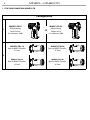
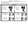
1.1 THE CONFIGURATIONS MINIECL/TR
Configuration
1
MINIECL/TR TU
Reector Housing
Tungsten version
Col. temperature: 3100K
MINIECL/TR DY
Reector Housing
Daylight version
Col. temperature: 5600K
2
MINIECL/TR L19
Optics for MINIECL/TR proler,
19° beam
MINIECL/TR L26
Optics for MINIECL7TR proler,
26° beam
MINIECL/TR L36
Optics for MINIECL/TR proler,
36° beam
MINIECL/TR L50
Optics for MINIECL/TR proler,
36° beam
OR

5
MINIECL - MINIECLTR
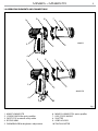
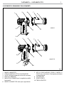
1.2 OPERATING ELEMENTS AND CONNECTIONS
Fig.3
MINIECLTR
MINIECL
1. MINIECL/MINIECLTR
2. LOCKING KNOB for optics proler
3. SAFETY EYE to attach safety cable.
4. ROTARY ARM
5. DIMMER KNOB for brightness adjustment
6. MINIECLL/MINIECLTRL optics proler
7. LENS FOCUS KNOBS
8. SHUTTER
9. GOBO HOLDER
10. TRACK-ADAPTER
4
5
10
9
3
1
2
8
7
6
4
5
9
3
1
2
8
7
6

MINIECL - MINIECLTR
6
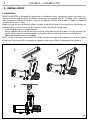
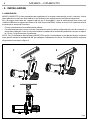
- 2 - INSTALLATION
2.1 MOUNTING
MINIECL/MINIECLTR is designed for applications in exhibition areas, commercial spaces, museums, res-
taurant, churches, and any other installation where size is an important factor. For xing, stable mounting
clips are required. The mounting place must be of sucient stability and be able to support a weight of
10 times of the unit’s weight.
When carrying out any installation, always comply scrupulously with all the regulations (particularly re-
garding safety) currently in force in the country in which the xture’s being used.
• Install the projector at a suitable location.
• Always additionally secure the projector with the safety rope from falling down. For this purpose, fas-
ten the safety rope at a suitable position so that the maximum fall of the projector will be 20 cm.
• Adjust the projector and use the knobs.
NOTE - For the installation of the MINIECLTR make sure that the ridge of the adaptor is in with the groove
of the track. Turn knobs 90° to connect the adaptor to the circuit. Please see the below instructions.
Fig.4
1
2
3

7
MINIECL - MINIECLTR
- 3 - FUNCTIONS AND SETTINGS
3.1 OPERATION
To turn on the MINIECL connect the supplied main cable to a socket (100-240 VAC-50/60 Hz). Then the unit
is ready for operation. You can also adjust the dimmer and zoom using the knobs.
To switch o, disconnect the mains plug from the socket. For a more convenient operation it is recom-
mended to connect the unit to a socket which can be switched on and o via a light switch.
NOTE - To operate the projector MINIECLTR you need a system track. The track system must be installed
and maintained by a suitably qualied person in compliance with latest construction and relevant legisla-
tion. It is the responsibility of the installer to ensure the electrical, mechanical and thermal compatibility
of the track system and the ttings. The connection to the main network of electric distribution must be
carried out by a qualied electrical installer.
ATTENTION - Mains voltage must be switched o before mounting; maintenance; insert and replace
Adaptors; spots and luminaires.
- 4 - MAINTENANCE
4.1 MAINTENANCE AND CLEANING THE UNIT
• Make sure the area below the installation place is free from unwanted persons during setup.
• Switch o the unit, unplug the main cable and wait until the unit has cooled down.
• All screws used for installing the device and any of its parts should be tightly fastened and should not
be corroded.
• Housings, xations and installation spots (ceiling, trusses, suspensions) should be totally free from any
deformation.
• The main cables must be in impeccable condition and should be replaced immediately even when a
small problem is detected.
• It is recommended to clean the front at regular intervals, from impurities caused by dust, smoke, or
other particles to ensure that the light is radiated at maximum brightness. For cleaning, disconnect the
main plug from the socket. Use a soft, clean cloth moistened with a mild detergent. Then carefully wipe
the part dry. For cleaning other housing parts use only a soft, clean cloth. Never use a liquid, it might
penetrate the unit and cause damage to it.
4.2 TROUBLESHOOTING
Problems Possible causes Checks and remedies
Fixture does not light up
• No mains supply
• Dimmer fader set to 0
• Faulty LED
• Check the power supply voltage
• Increase the value of the dimmer channels
• Replace the LED board
General low light intensity
• Dirty lens assembly
• Misaligned lens assembly
• Clean the xture regularly
• Install lens assembly properly
Fixture does not power up
• No power
• Loose or damaged power cord
• Check for power on power outlet
• Check power cord
Contact an authorized service center in case of technical problems or not reported in the table can not be
resolved by the procedure given in the table.

REV.001-07/15
Music & Lights S.r.l. si riserva ogni diritto di elaborazione in qualsiasi forma delle presenti istruzioni per l’uso.
La riproduzione - anche parziale - per propri scopi commerciali è vietata.
Al ne di migliorare la qualità dei prodotti, la Music&Lights S.r.l. si riserva la facoltà di modicare, in
qualunque momento e senza preavviso, le speciche menzionate nel presente manuale di istruzioni.
Tutte le revisioni e gli aggiornamenti sono disponibili nella sezione 'Manuali' sul sito www.musiclights.it

3
MINIECL - MINIECLTR
• MINIECL/MINIECLTR
• Cavo di alimentazione
• Manuale utente
Contenuto dell'imballo:
INDICE
Sicurezza
Avvertenze generaliAvvertenze generali
Attenzioni e precauzioni per l’installazioneAttenzioni e precauzioni per l’installazione
1 Disegno tecnico
1. 1 Congurazione MINIECL/TR1. 1 Congurazione MINIECL/TR
1. 2 Elementi di comando e di collegamento 1. 2 Elementi di comando e di collegamento
2 Installazione
2. 1 Montaggio2. 1 Montaggio
3 Funzioni e impostazioni
3. 1 Funzionamento3. 1 Funzionamento
4 Manutenzione
4. 1 Manutenzione e pulizia del sistema ottico4. 1 Manutenzione e pulizia del sistema ottico
4. 2 Risoluzione dei problemi4. 2 Risoluzione dei problemi
4
4
5
6
7
8
9
9
9

MINIECL - MINIECLTR
4
ATTENZIONE! Prima di effettuare qualsiasi operazione con l’unità, leggere con attenzione
questo manuale e conservarlo accuratamente per riferimenti futuri. Contiene informazioni
importanti riguardo l’installazione, l’uso e la manutenzione dell’unità.
SICUREZZA
Avvertenze generali
• I prodotti a cui questo manuale si riferisce sono conformi alle Direttive della Comunità Europea e per-
tanto recano la sigla .
• Il dispositivo funziona con pericolosa tensione di rete 230V~. Non intervenire mai al suo interno al di
fuori delle operazioni descritte nel presente manuale; esiste il pericolo di una scarica elettrica.
• È obbligatorio eettuare il collegamento ad un impianto di alimentazione dotato di un’eciente messa
a terra (apparecchio di Classe I secondo norma EN 60598-1). Si raccomanda, inoltre, di proteggere le
linee di alimentazione delle unità dai contatti indiretti e/o cortocircuiti verso massa tramite l’uso di
interruttori dierenziali opportunamente dimensionati.
• Le operazioni di collegamento alla rete di distribuzione dell’energia elettrica devono essere eettuate
da un installatore elettrico qualicato. Vericare che frequenza e tensione della rete corrispondono alla
frequenza ed alla tensione per cui l’unità è predisposta, indicate sulla targhetta dei dati elettrici.
• L’unità non per uso domestico, solo per uso professionale.
• Evitare di utilizzare l’unità:
- in luoghi soggetti a vibrazioni, o a possibili urti;
- in luoghi a temperatura superiore ai 45°C.
• Evitare che nell’unità penetrino liquidi inammabili, acqua o oggetti metallici.
• Non smontare e non apportare modiche all’unità.
• Tutti gli interventi devono essere sempre e solo eettuati da personale tecnico qualicato. Rivolgersi al
più vicino centro di assistenza tecnica autorizzato.
• Se si desidera eliminare il dispositivo denitivamente, consegnarlo
per lo smaltimento ad un’istituzione locale per il riciclaggio.
Attenzioni e precauzioni per l’installazione
• Se il dispositivo dovesse trovarsi ad operare in condizioni dierenti da quelle descritte nel presente
manuale, potrebbero vericarsi dei danni; in tal caso la garanzia verrebbe a decadere. Inoltre, ogni altra
operazione potrebbe provocare cortocircuiti, incendi, scosse elettriche, rotture etc.
• Prima di iniziare qualsiasi operazione di manutenzione o pulizia sull’unità togliere la tensione dalla rete
di alimentazione.
• È assolutamente necessario proteggere l’unità per mezzo di una fune di sicurezza. Nell’eseguire qual-
siasi intervento attenersi scrupolosamente a tutte le normative (in materia di sicurezza) vigenti nel
paese di utilizzo.
• Installare l’unità in un luogo ben ventilato.
• Mantenere i materiali inammabili ad una distanza di sicurezza dall’unità.
• I ltri, le lenti o gli schermi ultravioletti se danneggiati possono limitare la loro ecienza.
• I LED devono essere sostituiti se danneggiati o termicamente deformati.
• Non guardare direttamente il fascio luminoso. Tenete presente che i veloci cambi di luce possono pro-
vocare attacchi d’epilessia presso persone fotosensibili o epilettiche.
• Non toccare l’alloggiamento del prodotto quando è in funzione perché potrebbe essere molto caldo.
• Questo prodotto è stato progettato e costruito esclusivamente per l’utilizzo indicato in questa docu-
mentazione. Qualsiasi altro utilizzo non espressamente indicato potrebbe pregiudicare la funzionalità
del prodotto e/o rappresentare fonte di pericolo.
• Si declina qualsiasi responsabilità derivata dall’uso improprio del prodotto.

5
MINIECL - MINIECLTR
- 1 - DISEGNO TECNICO
Fig.1 - Disegno tecnico
Fig.2 - Disegno tecnico

MINIECL - MINIECLTR
6
1.1 CONFIGURAZIONE MINIECL/TR
Configuration
1
MINIECL/TR TU
Reector Housing
Tungsten version
Col. temperature: 3100K
MINIECL/TR DY
Reector Housing
Daylight version
Col. temperature: 5600K
2
MINIECL/TR L19
Optics for MINIECL/TR proler,
19° beam
MINIECL/TR L26
Optics for MINIECL7TR proler,
26° beam
MINIECL/TR L36
Optics for MINIECL/TR proler,
36° beam
MINIECL/TR L50
Optics for MINIECL/TR proler,
36° beam
OR

Fig.3
MINIECLTR
MINIECL
1. MINIECL/MINIECLTR
2. VITE DI FISSAGGIO OTTICA SAGOMATORE
3. SAFETY EYE per l’aggancio al cavo di sicurezza
4. BRACCIO GIREVOLE
5. MANOPOLA DIMMER per la regolazione della
luminosità
6. MINIECLL/MINIECLTRL ottica per sagomatore
7. VITE DI REGOLAZIONE ZOOM E MESSA A
FUOCO per zoommare l'immagine proiettata
in modo chiaro
8. OTTURATORE
9. PORTA GOBOS
10. TRACK-ADAPTER
4
5
10
9
3
1
2
8
7
6
4
5
9
3
1
2
8
7
6
7
MINIECL - MINIECLTR
1.2 ELEMENTI DI COMANDO E COLLEGAMENTI

Fig.4
MINIECL - MINIECLTR
8
- 2 - INSTALLAZIONE
2.1 MONTAGGIO
MINIECL/MINIECLTR è stato progettato per applicazioni in campo commerciale, musei, ristoranti, chiese,
teatri educativi e qualsiasi altro ambito in cui le dimensioni rappresentano un fattore importante.
Per il ssaggio occorrono dei supporti robusti per il montaggio. L’area di collocazione deve avere una
stabilità suciente e supportare almeno 10 volte il peso dell’unità. Inoltre assicurarsi di rispettare tutte le
avvertenze in materia di sicurezza.
• Fissare il proiettore ad una collocazione idonea.
• È assolutamente necessario assicurare il proiettore contro la caduta utilizzando un cavo di sicurezza: in
particolare collegare il cavo in un punto adatto in modo che la caduta del proiettore non possa supera-
re i 20 cm. Quindi orientare il proiettore.
NOTA - Per l’installazione del proiettore MINIECLTR inserire il track adapter in un idoneo binario a quattro
linee quindi ruotare la manopola di 90° per collegare l’adattatore al circuito. Far riferimento alla sequenza
di operazioni mostrate in gura 4.
1
2
3

9
MINIECL - MINIECLTR
Anomalie Possibili cause Controlli e rimedi
Il proiettore non illumina
• Mancanza di alimentazione di rete
• Dimmer impostato a 0
• LED difettoso/i
• Vericare la presenza della tensione alimentazione
• Incrementare i valori del canale dimmer
• Sostituire scheda LED
Bassa intensità di luce generale
• Lenti sporche
• Lente disallineata
• Pulire il dispositivo regolarmente
• Installare il gruppo ottico correttamente
Il proiettore non è alimentato
• Mancanza di alimentazione di rete
• Cavo di alimentazione danneggiato
• Vericare la presenza della tensione alimentazione
• Controllare il cavo di alimentazione
Rivolgersi a un centro di assistenza tecnico autorizzato nel caso in cui il problema non sia riportato in
tabella.
- 3 - FUNZIONI E IMPOSTAZIONI
3.1 FUNZIONAMENTO
Per accendere il MINIECL, inserire la spina del cavo di alimentazione in una presa di rete (100-240V~/50-
60Hz). Eettuare le regolazioni del dimmer e dello zoom mediante le relative manopole. Dopo l’utilizzo
spegnere il dispositivo, staccare la spina dalla presa di rete. Per maggiore comodità è consigliabile collega-
re l’unità con una presa comandata da un interruttore.
NOTA - Per il funzionamento del proiettore MINIECLTR è necessario realizzare invece un sistema track.
Il sistema di binari deve essere installato e gestito da personale qualicato in conformità con le relative
normative vigenti nel paese di utilizzo. È responsabilità dell’installatore garantire la compatibilità elettrica,
meccanica e termica del sistema. In particolare, le operazioni di collegamento alla rete di distribuzione
dell’energia elettrica devono essere eettuate da un installatore elettrico qualicato.
ATTENZIONE - Assicuararsi di togliere la tensione di alimentazione prima di iniziare qualsiasi intervento di
manutenzione, inserimento e sostituzione di track-adpter e dispositivi di illuminazione.
- 4 - MANUTENZIONE
4.1 MANUTENZIONE E PULIZIA DEL SISTEMA OTTICO
• Durante gli interventi, assicurarsi che l’area sotto il luogo di installazione sia libera da personale non
qualicato.
• Spegnere l’unità, scollegare il cavo di alimentazione ed aspettare nché l’unità non si sia rareddata.
• Tutte le viti utilizzate per l’installazione dell’unità e le sue parti devono essere assicurate saldamente e
non devono essere corrose.
• Alloggiamenti, elementi di ssaggio e di installazione (sotto, truss, sospensioni) devono essere total-
mente esenti da qualsiasi deformazione.
• I cavi di alimentazione devono essere in condizione impeccabile e devono essere sostituiti immediata-
mente nel momento in cui anche un piccolo problema viene rilevato.
• Si dovrebbe procedere, ad intervalli regolari, alla pulizia della parte frontale per asportare polvere,
fumo e altre particelle. Solo così, la luce può essere irradiata con la luminosità massima. Per la pulizia
usare un panno morbido, pulito e un detergente per vetri come si trovano in commercio. Quindi asciu-
gare le parti delicatamente.
4.2 RISOLUZIONE DEI PROBLEMI

Note


©2020 Music & Lights S.r.l.
PROLIGHTS è un brand di proprietà della Music & Lights S.r.l. PROLIGHTS is a brand of Music & Lights S.r.l .company.
MUSIC & LIGHTS S.r.l. - Phone +39 0771 72190 - www.musiclights.it
-
 1
1
-
 2
2
-
 3
3
-
 4
4
-
 5
5
-
 6
6
-
 7
7
-
 8
8
-
 9
9
-
 10
10
-
 11
11
-
 12
12
-
 13
13
-
 14
14
-
 15
15
-
 16
16
-
 17
17
-
 18
18
-
 19
19
-
 20
20


ProLights 28W track mounted mini LED profile Manuale utente
- Tipo
- Manuale utente
- Questo manuale è adatto anche per
in altre lingue
Documenti correlati
-
ProLights 28W track mounted mini LED profile Manuale utente
-
-
-
-
-
-
-
-
ProLights 28 W track mounted mini LED profile Manuale utente
-