Rugged CCTV Workhorse 120-4 Operating Instructions & User Manual
- Categoria
- Videoregistratori digitali (DVR)
- Tipo
- Operating Instructions & User Manual


1
Statement of Compliance with FCC
Model Name: Workhorse 120-4
This device complies with Section 15 of the FCC Rules. Operation is covered by the following
provisions: (1) This device shall not cause harmful interference, and; (2) This device must accept
any interference received including interference that may cause unintended operations.
Warning
- Unauthorized reproduction of all or part of the contents of this manual is strictly prohibited.
- The figures in this manual are for illustration purposes only (may differ from the actual product).
- The specifications and design of the product are subject to change without prior notice for purposes
of quality improvement.
Cautions
To get the best use out of the product, be sure to read the cautions before using the product.
For your safety, please take note of the following:
Caution
1. To prevent electric shock when installing, moving, or opening the DVR and peripheral
devices, connect and disconnect the cables as instructed in this manual. All cables
must be connected to grounded outlets.
2. Install the DVR such that it is easy to disconnect the power cord.
3. Do not use the DVR in water or in wet places (may cause electric shock).
4. Keep the vinyl packing materials used for the DVR or other peripheral devices out of
reach of children (may cause suffocation).
DVR Installation Environment
1. The operating temperature should be 0˚C ~ 40˚C, and the operating humidity, 10% ~
80%.
2. Install the DVR in a safe, vibration-free place.
3. Install the DVR in a well-ventilated place.
4. To protect the hard drive from data loss and problems, install the DVR away from
magnetic interference.
5. When a standard rack is not used, use a separate table that allows gaps of 60cm
from the floor, 50cm from the ceiling, and 20cm from the wall.
Safety Notes on the DVR
1. When installing additional boards and HDDs, disconnect the power cable and turn off
the power of the DVR completely.
2. Keep the product away from heat sources such as heaters.
3. Do not use a damaged power cord.
4. To prevent and minimize trouble due to magnetic interference and electric surge, use
only grounded cables and outlets.

2
5. Do not touch the power supply while the power cord is connected. Even if the switch
is turned off, electricity continues to flow through the cable and power supply while the
power cord is connected.
6. Do not place heavy objects on the product.
7. Do not drop conductive objects into the ventilation holes.
8. Allow sufficient space for system cabling (video inputs/loop outs) on the back of the
unit.
9. Use only the items indicated in this manual. Do not attempt to disassemble, repair, or
remodel the product without permission. IT WILL VOID YOUR WARRANTY.
10. Incorrect system setup may cause undesirable effects.
11. Shut down the system properly as instructed in this manual.
12. The UPS power supply contains a small amount of toxic substances. Improper
installation of the battery, exposure to fire or moisture, disassembly or short circuit
may cause explosion. Keep the battery pack out of reach of infants or children.
Safety Notes on the Lithium Battery
1. Replace lithium batteries as instructed in this manual.
2. Dispose of used lithium batteries properly.
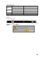
Warnings and Cautions are indicated as follows:
Possible injury or product damage
Risk of minor injury or product damage

3
Workhorse 120-4
C/O/N/T/E/N/T/S
Workhorse 120-4
Statement of Compliance with FCC....................................... 1
Warning...................................................................................................1
Cautions .................................................................................................1
C/O/N/T/E/N/T/S ...........................................................................................3
1. Overview..................................................................................................6
1-1. About the Product.....................................................................................................6
1-2. Major Features..........................................................................................................6
1-3. Components..............................................................................................................7
2. Installation and Connection...................................................................8
2-1. Name and Features of Each Part.............................................................................8
2-1-1. Front Part.......................................................................................................................................8
2-1-2. Rear Part........................................................................................................................................9
2-2. Installation and Connection ....................................................................................10
2-2-2. Adding a Hard Drive ..................................................................................................................13
2-2-3. CD-RW/DVD-RW ......................................................................................................................17
3. Operation and Setup Tools ..................................................................18
3-1. Front Buttons ..........................................................................................................18
3.2 Remote Control........................................................................................................19
3-3. Mouse .....................................................................................................................22
4. System Operation .................................................................................23
4-1. Starting and Shutting down the System..................................................................23
4-1-1. Starting the System......................................................................................................................23
4-1-2. Shutting down the System ...........................................................................................................23
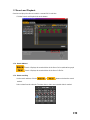
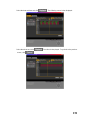
4-2. System Login..........................................................................................................25
4-2-1. User Account...............................................................................................................................25
4-2-2. Login ...........................................................................................................................................25
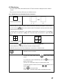
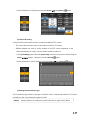
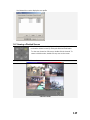
4-3. Monitoring ...............................................................................................................27
4-3-1. Divided Screen and Automatic Screen Conversion .....................................................................27
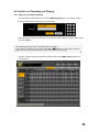
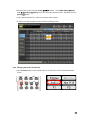
4-4. Audio Live, Recording, and Playing........................................................................28
4-4-1. Audio Live and Recording Setup.................................................................................................28
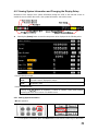
4-4-2. Changing the Audio Live Channel ..............................................................................................29

4
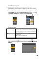
4-5. Viewing System Information and Changing the Display Setup ..............................31
4-5-1. Viewing System Information.......................................................................................................31
4-5-2. Brightness Control.......................................................................................................................33
4-5-3. Adjusting the Contrast .................................................................................................................33
4-5-4. Camera Control............................................................................................................................33
4-5-5. TV Control...................................................................................................................................34
4-5-6. Language .....................................................................................................................................34
4-5-7. Displaying/Hiding the Camera Name..........................................................................................35
4-5-8. Controlling the Screen Border .....................................................................................................35
4-5-9. Reset ............................................................................................................................................36
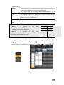
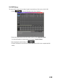
4-6. System Log.............................................................................................................37
4-6-1. Log Type .....................................................................................................................................37
4-6-2. Viewing the System Log .............................................................................................................37
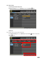
4-7. Record.....................................................................................................................40
4-7-1. Recording Type ...........................................................................................................................40
4-7-2. Recording Setup ..........................................................................................................................40
4-7-3. Viewing the Recording Status .....................................................................................................40
4-7-4. Starting and Stopping Record All ................................................................................................41
4-7-5. Watermark ...................................................................................................................................42
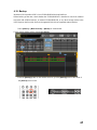
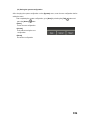
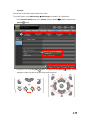
4-8. Search.....................................................................................................................43
4-8-1. Selecting Search Mode ................................................................................................................43
4-8-2. Search Method.............................................................................................................................44
4-8-3. Selecting the Search Tool ............................................................................................................44
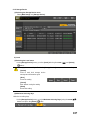
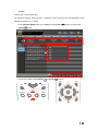
4-8-4.Multi-channel ...............................................................................................................................47
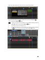
4-8-5. Multi-hour....................................................................................................................................48
4-8-6. Multi-date ....................................................................................................................................49
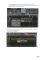
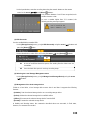
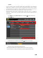
4-9. Play.........................................................................................................................51
4-9-1. Selecting Play Mode....................................................................................................................51
4-9-2. Playing and Controlling the Play Speed ......................................................................................53
4-9-3. Playing on a Divided Screen........................................................................................................54
4-9-4. Changing the Audio Channel.......................................................................................................56
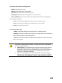
4-9-5. Mute ............................................................................................................................................57
4-9-6. Smart Search................................................................................................................................58
4-9-7. Digital Zoom-in ...........................................................................................................................61
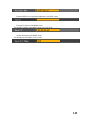
4-10. Backup..................................................................................................................63
4-11. PTZ Camera Control.............................................................................................67
4-11-1. Conditions for Using PTZ..........................................................................................................67
4-11-2. Shifting to PTZ Mode................................................................................................................67
4-11-3. PTZ Control...............................................................................................................................68

5
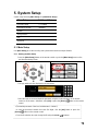
5. System Setup ........................................................................................70
5-1. Main Setup..............................................................................................................70
5-1-1. Starting the Main Setup ...............................................................................................................70
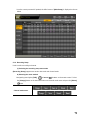
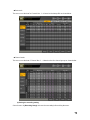
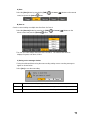
5-1-2. Recording Setup ..........................................................................................................................71
5-1-3. Recording Schedule.....................................................................................................................89
5-1-4. System .........................................................................................................................................95
5-1-5.Storage Device............................................................................................................................107
5-1-6.NTP ............................................................................................................................................117
5-1-7. Advanced...................................................................................................................................121
5-2. Additional Setup....................................................................................................125
5-2-1. Selecting Additional Setup ........................................................................................................125
5-2-2.PTZ Setup...................................................................................................................................126
5-2-3. Network Setup ...........................................................................................................................130
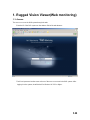
1. Rugged Vision Viewer (Web monitoring).......................................... 144
1-1.Access....................................................................................................................144
1-2.Description of the Basic Features..........................................................................146
1-3. Audio.....................................................................................................................146
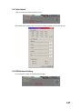
1-4. Color Adjust ..........................................................................................................147
1-5. DVR Network Setting............................................................................................147
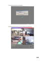
1-6. Viewing a Divided Screen.....................................................................................149
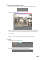
1-7.Search and Playback.............................................................................................150
1-7-2. Search Method...........................................................................................................................150
1-7-3. Search and Play .........................................................................................................................150
1-7-4. Playback Control .......................................................................................................................152
1-7-5. Screen Description.....................................................................................................................152
1-8. DVR Setup............................................................................................................153
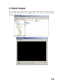
2. Quick Viewer .......................................................................................154
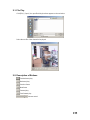
2-1. File Play ................................................................................................................155
2-2. Description of Buttons...........................................................................................155
2-3. Version Information...............................................................................................156
A/P/P/E/N/D/I/X ........................................................................................157
1. PTZ Camera Protocol ....................................................................... 158
2. Recommended HDD ......................................................................... 158
3. Recommended USB 2.0 Device....................................................... 159
Memory Stick......................................................................................................159
2.5" Portable USB HDD......................................................................................159
CD-RW, DVD-RW..............................................................................................159

6
1. Overview
1-1. About the Product
Workhorse 120-4 is a digital video monitoring system. This product can display and record, at a high
resolution rate, the video data of up to four cameras.
Front buttons, remote control, and mouse are provided for the user’s convenience; along with
network features including monitoring and remote system setup.
Workhorse 120-4 supports up to 120/100 (NTSC/PAL) fps.
1-2. Major Features
Stable Standalone DVR (embedded Linux)
Video output
- Loop output: 4 BNC
- Monitor output: 1 BNC, 1 VGA
Simultaneous real-time display, recording, and playback at 120/100 (NTSC/PAL) fps
Resolution
- NTSC: 320×240, 640×240, 640×480
- PAL: 320×288, 640×288, 640×576
Compression type: MPEG4 (video)/G.726 (audio)
Backup/Copy: Ethernet, USB2.0, Built-in CD-RW
System operation: Front buttons/Remote control/Network/USB2.0 mouse/System
control
2-channel audio input
Various-network-interfaces
- Cable modem, Ethernet, ADSL/DHCP client
System automation (all features are remote controllable)
NTP support
Various-recording-modes
- Auto, Continuous, Event (sensor, motion, sound) recording
Recording schedule
Multi-language support, Automatic emailing
PTZ control through RS485 communication
Remote monitoring software, Remote monitoring through the web browser, PDA
viewer
Storage device
- Internal storage device: Max. of 4HDD, 2TB

7
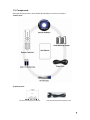
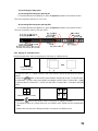
1-3. Components
After unpacking the product, check whether the following accessories are included:
1) Basic parts
2) Optional parts
DIO (Sensor/Relay) Extension Module
DIO (Sensor/Relay) Extension Module Cable

8
2. Installation and Connection
2-1. Name and Features of Each Part
Buttons are conveniently located on the front panel of the Workhorse 120-4, and various interfaces,
on its rear panel. Workhorse 120-4 can be easily installed in a standard rack using the rack mounting
handles (on the left and right sides).
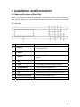
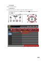
2-1-1. Front Part
No Name Features
1 Remote
The green light is ON when the remote control is
accessing the DVR
2 Network
The green light is ON when the DVR is being accessed
through the network
3 Backup
The green light is ON when the DVR is making a
backup
4 HDD
The green light is turned ON when the hard drive is
operating.
5 Alarm
The red light is ON when an alarm is triggered.
6 CD-RW/DVD-RW
CD-RW/DVD-RW installation slot
7 Numeric buttons
Numeric buttons
8 USB
External backup device or USB mouse connection
9 Remote control sensor
Remote control reception sensor
10 Power
System power ON/OFF or Selection button

9
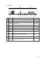
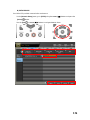
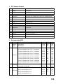
2-1-2. Rear Part
No Name Features Form
1 AC in
Power cable connection to the body
2 Ethernet
ADSL, Cable modem, and Ethernet 10/100 Base-T connection RJ-45
3 RS-232C
PSTN/ISDN modem connection or Serial cable connection for
system upgrade
D-SUB 9 pin
4 RS485
PTZ camera control cable connection RJ-11 6-pin
5 VGA
VGA monitor connection D-SUB 15 pin
6 TV
CCTV monitor connection BNC
7 Video in
Video camera connection BNC
8 Audio in
Audio input connection (line only input)
- 2-line
RCA
9 Audio out
Audio output connection (line only output)
-1-line
RCA
10 DIO
DIO (sensor/relay) extension module connection D-SUB 25 pin
11
Video out
(loop-out)
Video signal loop-out connection BNC

10
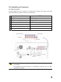
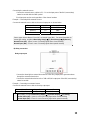
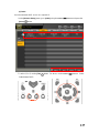
2-2. Installation and Connection
2-2-1. Basic Connection
Connect the DVR to the CCTV cameras, CCTV monitor (or PC monitor), PTZ camera control cable,
audio input/output port, network, and sensor as shown below:
Connection Device DVR Port
1
CCTV camera BNC Video input
2
CCTV monitor (or PC monitor) BNC or VGA
3
PTZ camera control cable RS485
4
Audio input/output Audio input (line in)/Audio output (line out)
5
LAN cable Ethernet
6
DIO (sensor/relay) extended module DIO
1. The inputted video type must be either NTSC or PAL; these two types must not be
used together.
2. The inputted video type (NTSC/PAL) is automatically recognized upon the initial
operation of the system.
Video Loop Output
A
udio Output
A
udio Input
Video Input
PTZ Camera
CRT Monitor
CCTV Monitor
CCTV Camera
Power

11
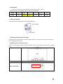
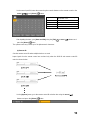
(1) PTZ camera
To use a PTZ camera, connect the control cable to the RS485 connector.
RS485 uses the RJ-11 6-pin type. Below is the pin arrangement:
Pin 1 2 3 4 5 6
RS485
GND TR+ TR- TR+ TR- GND
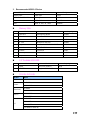
(2) Audio input/output
There are two audio input ports and one audio output port.
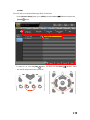
(3) DIO (sensor/relay) extension module
Connect the DIO (sensor/relay) extension module to the DIO connector on the rear side using a D-
SUB 25-type extension cable.
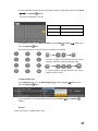
A) External sensor connection option
The DIO (sensor/relay) extension module consists of four sensor input ports and one relay output
port.
DIO (sensor/relay) extended module
Sensor input port
A
udio Output
A
udio Intput

12
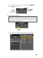
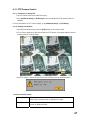
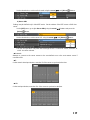
Connecting the external sensors
Connect the external sensor cables to S1 ~ S4 on the input ports of the DIO (sensor/relay)
extension module with the GND symbol.
Each input port may be used regardless of the channel number.
Example - Connecting three external sensors
Connect the external sensor cable to the sensor input ports as shown below:
External Sensor Input Port Ground Port
Sensor 1 S1 GND
Sensor 2 S3 GND
Sensor 3 S4 GND
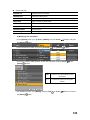
Sensor types include Normal Close (NC) or Normal Open (NO). For more information on
sensor type setting, see {5-1-2 Recording Setup} {(7) Event Setup} {(B) Sensor}.
Normal Close (NC): Opens in case of incoming signal when closed normally
Normal Open (NO): Closes in case of incoming signal when opened normally
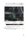
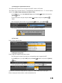
B) Relay connection
Relay output port
Connect the alarm light or external alarm device to the relay output port to generate alarms
through the external alarm device.
Connect the external alarm device to the COM or NC/NO output port of the DIO (sensor/relay)
extension module.
Example - Connecting one external sensor
Connect the external sensor cable to the relay output port:
External Alarm Device Output Port Ground Port
Relay 1 NC or NO COM
Relay types include Normal Close (NC) or Normal Open (NO). For more information on
relay setting, see {5-1-2 Recording Setup} {(8) Alarm Output} {(C) Relay}.
Normal Close (NC): Opens in case of incoming signal when closed normally
Normal Open (NO): Closes in case of incoming signal when opened normally

13
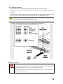
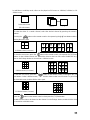
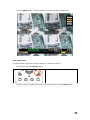
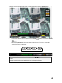
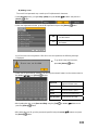
2-2-2. Adding a Hard Drive
Up to four hard drive s may be installed in the system using two hard drive cables.
Each hard drive cable can connect two hard drive s, which must be configured in master-slave
structure.
In the absence of CD-RW, two hard drive bays are installed: one on the right and the other on the
left. If there is a CD-RW, however, only two hard drive bays are installed on the right.
The jumper setting method varies by manufacturer or model. Refer to the jumper setting
information marked on the front side of the hard drive .
Example - Setting the jumpers for the western digital WD1200 hard drive
Adding a Hard Drive
1) Before installing the HDD, turn off the DVR and disconnect the power cord.
2) Never touch grounded metallic objects when installing the HDD (may cause the body to
absorb static electricity, which in turn can cause problems in the DVR).
3) After installing the HDD, do not turn the power ON until the top cover is closed. Never use the
DVR with the top cover opened.

14
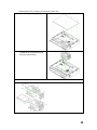
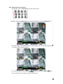
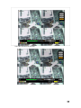
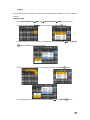
Before turning OFF the power, shut down the system first.
Unscrew and open the upper case.
Unscrew the hard drive bay using a
screwdriver and separate the hard
drive bay from the body.
Insert the hard drives into the hard drive bay

15
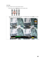
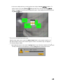
Connect the hard drive power cable and hard drive connection cable to the corresponding
plugs.
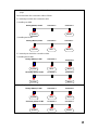
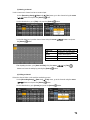
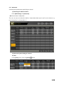
Connect the hard drive connection cable as follows:
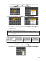
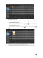
1. Connecting one hard drive connection cable
1) Installing one HDD
System Master
Primary (Master) E- IDE Connector 0
Connector 1
2) Installing two HDDs
System Master
Slave
Primary (Master) E- IDE Connector 0
Connector 1
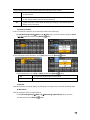
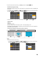
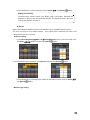
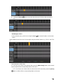
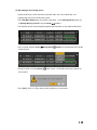
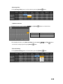
2. Connecting two hard drive connection cables
1) Installing three HDDs
System Master
Slave
Primary (Master) E- IDE Connector 0
Connector 1
System Master
Secondary (Slave) E- IDE Connector 0
Connector 1
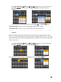
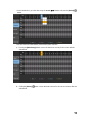
2) Installing four HDDs
System Master
Slave
Primary (Master) E- IDE Connector 0
Connector 1
System MasterSlave
Secondary (Slave) E- IDE Connector 0
Connector 1

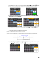
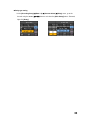
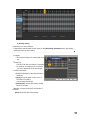
16
Place the hard drive bay back in the DVR and fasten with screws.
Close the upper case and fasten the screws.
Turn the power ON and start the system.
After adding a hard drive, select {Main Setup} -> {Storage Device} -> {Local} -> {3.
Manage Local Storage Device}. For more information, see {5. System Setup} -> {5-1
Main Setup} -> {5-1-5 Storage Device}.

17
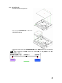
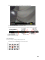
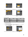
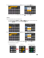
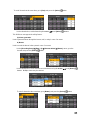
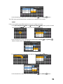
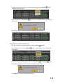
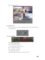
2-2-3. CD-RW/DVD-RW
Unscrew and open the upper case.
Screw in the CD-RW/DVD-RW on the front
CD-RW/DVD-RW bay.
Connect the power cord of the CD-RW/DVD-RW and the E-IDE cable to the corresponding
ports.
Note ! Before connecting the E-IDE cable to the slave E-IDE, set the jumper of the CD-
RW/DVD-RW as slave.

18
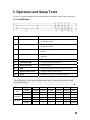
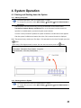
3. Operation and Setup Tools
The user can operate Workhorse 120-4 easily using the front buttons, remote control, and mouse.
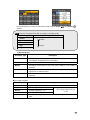
3-1. Front Buttons
No. Name Features
1 Remote
The green light is ON when the remote control is
accessing the DVR
2 Network
The green light is ON when the DVR is being accessed
through the network
3 Backup
The green light is ON when the DVR is making a
backup
4 HDD
The green light is turned ON when the hard drive is
operating.
5 Alarm The red light is ON when an alarm is triggered.
6 CD-RW/DVD-RW CD-RW/DVD-RW installation slot
7 Numeric buttons Numeric buttons
8 USB External backup device or USB mouse connection
9 Remote control sensor Remote control reception sensor
10 Power System power ON/OFF or Selection button
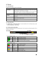
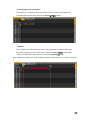
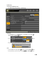
The front buttons are used only for inputting numeric data. Use the mouse or remote control
for the other features.
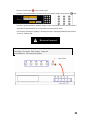
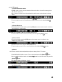
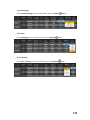
Menu Key Type 1st 2nd 3rd 4th 5th Power
Short 1CH full 2CH full 3CH full 4CH full Quad Power
Live
Long X X X Status X Select
Short 1 3 5 7 9 ESC
Password
Long 2 4 6 8 0 Select
Short 1CH full 2CH full 3CH full 4CH full Quad X
Playback
Long X X X X X Select

19
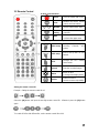
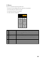
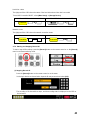
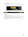
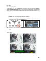
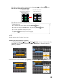
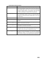
3.2 Remote Control
A. Basic control buttons
Power
Turns the system ON or OFF
Lock
Disables the mouse, remote
control, and front buttons
~
Number
Used to input numeric data
ID
setting
Used to set the remote
control ID
ESC
Exits the current menu
or selects the upper menu
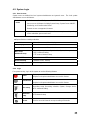
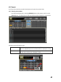
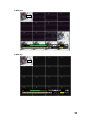
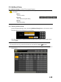
B. System operation and setup buttons
MAIN
SETUP
Main setup
Used to set up the recording,
recording schedule, and
system
APP.
SETUP
APP setup
Used to set up the PTZ and
network
PTZ
PTZ
Changes the PTZ camera
control mode
SEARCH
Search
Searches recorded images
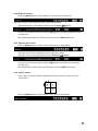
Move
Moves an item
or changes the display mode
Select
Selects an item or
converts screens sequentially
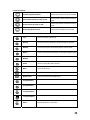
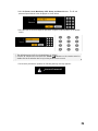
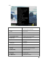
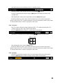
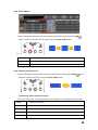
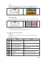
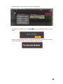
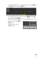
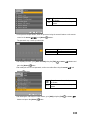
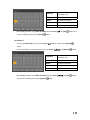
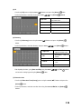
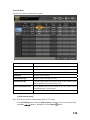
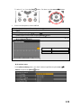
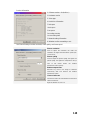
Setting the remote control ID
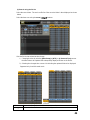
Example - Setting the remote control ID as 1
Select the [ID] button and input the two-digit remote control ID. Afterward, press the [ID] button
again.
To control all DVRs with different IDs, set the remote control ID as 999.
La pagina si sta caricando...
La pagina si sta caricando...
La pagina si sta caricando...
La pagina si sta caricando...
La pagina si sta caricando...
La pagina si sta caricando...
La pagina si sta caricando...
La pagina si sta caricando...
La pagina si sta caricando...
La pagina si sta caricando...
La pagina si sta caricando...
La pagina si sta caricando...
La pagina si sta caricando...
La pagina si sta caricando...
La pagina si sta caricando...
La pagina si sta caricando...
La pagina si sta caricando...
La pagina si sta caricando...
La pagina si sta caricando...
La pagina si sta caricando...
La pagina si sta caricando...
La pagina si sta caricando...
La pagina si sta caricando...
La pagina si sta caricando...
La pagina si sta caricando...
La pagina si sta caricando...
La pagina si sta caricando...
La pagina si sta caricando...
La pagina si sta caricando...
La pagina si sta caricando...
La pagina si sta caricando...
La pagina si sta caricando...
La pagina si sta caricando...
La pagina si sta caricando...
La pagina si sta caricando...
La pagina si sta caricando...
La pagina si sta caricando...
La pagina si sta caricando...
La pagina si sta caricando...
La pagina si sta caricando...
La pagina si sta caricando...
La pagina si sta caricando...
La pagina si sta caricando...
La pagina si sta caricando...
La pagina si sta caricando...
La pagina si sta caricando...
La pagina si sta caricando...
La pagina si sta caricando...
La pagina si sta caricando...
La pagina si sta caricando...
La pagina si sta caricando...
La pagina si sta caricando...
La pagina si sta caricando...
La pagina si sta caricando...
La pagina si sta caricando...
La pagina si sta caricando...
La pagina si sta caricando...
La pagina si sta caricando...
La pagina si sta caricando...
La pagina si sta caricando...
La pagina si sta caricando...
La pagina si sta caricando...
La pagina si sta caricando...
La pagina si sta caricando...
La pagina si sta caricando...
La pagina si sta caricando...
La pagina si sta caricando...
La pagina si sta caricando...
La pagina si sta caricando...
La pagina si sta caricando...
La pagina si sta caricando...
La pagina si sta caricando...
La pagina si sta caricando...
La pagina si sta caricando...
La pagina si sta caricando...
La pagina si sta caricando...
La pagina si sta caricando...
La pagina si sta caricando...
La pagina si sta caricando...
La pagina si sta caricando...
La pagina si sta caricando...
La pagina si sta caricando...
La pagina si sta caricando...
La pagina si sta caricando...
La pagina si sta caricando...
La pagina si sta caricando...
La pagina si sta caricando...
La pagina si sta caricando...
La pagina si sta caricando...
La pagina si sta caricando...
La pagina si sta caricando...
La pagina si sta caricando...
La pagina si sta caricando...
La pagina si sta caricando...
La pagina si sta caricando...
La pagina si sta caricando...
La pagina si sta caricando...
La pagina si sta caricando...
La pagina si sta caricando...
La pagina si sta caricando...
La pagina si sta caricando...
La pagina si sta caricando...
La pagina si sta caricando...
La pagina si sta caricando...
La pagina si sta caricando...
La pagina si sta caricando...
La pagina si sta caricando...
La pagina si sta caricando...
La pagina si sta caricando...
La pagina si sta caricando...
La pagina si sta caricando...
La pagina si sta caricando...
La pagina si sta caricando...
La pagina si sta caricando...
La pagina si sta caricando...
La pagina si sta caricando...
La pagina si sta caricando...
La pagina si sta caricando...
La pagina si sta caricando...
La pagina si sta caricando...
La pagina si sta caricando...
La pagina si sta caricando...
La pagina si sta caricando...
La pagina si sta caricando...
La pagina si sta caricando...
La pagina si sta caricando...
La pagina si sta caricando...
La pagina si sta caricando...
La pagina si sta caricando...
La pagina si sta caricando...
La pagina si sta caricando...
La pagina si sta caricando...
La pagina si sta caricando...
La pagina si sta caricando...
La pagina si sta caricando...
La pagina si sta caricando...
La pagina si sta caricando...
La pagina si sta caricando...
La pagina si sta caricando...
La pagina si sta caricando...
La pagina si sta caricando...
-
 1
1
-
 2
2
-
 3
3
-
 4
4
-
 5
5
-
 6
6
-
 7
7
-
 8
8
-
 9
9
-
 10
10
-
 11
11
-
 12
12
-
 13
13
-
 14
14
-
 15
15
-
 16
16
-
 17
17
-
 18
18
-
 19
19
-
 20
20
-
 21
21
-
 22
22
-
 23
23
-
 24
24
-
 25
25
-
 26
26
-
 27
27
-
 28
28
-
 29
29
-
 30
30
-
 31
31
-
 32
32
-
 33
33
-
 34
34
-
 35
35
-
 36
36
-
 37
37
-
 38
38
-
 39
39
-
 40
40
-
 41
41
-
 42
42
-
 43
43
-
 44
44
-
 45
45
-
 46
46
-
 47
47
-
 48
48
-
 49
49
-
 50
50
-
 51
51
-
 52
52
-
 53
53
-
 54
54
-
 55
55
-
 56
56
-
 57
57
-
 58
58
-
 59
59
-
 60
60
-
 61
61
-
 62
62
-
 63
63
-
 64
64
-
 65
65
-
 66
66
-
 67
67
-
 68
68
-
 69
69
-
 70
70
-
 71
71
-
 72
72
-
 73
73
-
 74
74
-
 75
75
-
 76
76
-
 77
77
-
 78
78
-
 79
79
-
 80
80
-
 81
81
-
 82
82
-
 83
83
-
 84
84
-
 85
85
-
 86
86
-
 87
87
-
 88
88
-
 89
89
-
 90
90
-
 91
91
-
 92
92
-
 93
93
-
 94
94
-
 95
95
-
 96
96
-
 97
97
-
 98
98
-
 99
99
-
 100
100
-
 101
101
-
 102
102
-
 103
103
-
 104
104
-
 105
105
-
 106
106
-
 107
107
-
 108
108
-
 109
109
-
 110
110
-
 111
111
-
 112
112
-
 113
113
-
 114
114
-
 115
115
-
 116
116
-
 117
117
-
 118
118
-
 119
119
-
 120
120
-
 121
121
-
 122
122
-
 123
123
-
 124
124
-
 125
125
-
 126
126
-
 127
127
-
 128
128
-
 129
129
-
 130
130
-
 131
131
-
 132
132
-
 133
133
-
 134
134
-
 135
135
-
 136
136
-
 137
137
-
 138
138
-
 139
139
-
 140
140
-
 141
141
-
 142
142
-
 143
143
-
 144
144
-
 145
145
-
 146
146
-
 147
147
-
 148
148
-
 149
149
-
 150
150
-
 151
151
-
 152
152
-
 153
153
-
 154
154
-
 155
155
-
 156
156
-
 157
157
-
 158
158
-
 159
159
-
 160
160
-
 161
161


Rugged CCTV Workhorse 120-4 Operating Instructions & User Manual
- Categoria
- Videoregistratori digitali (DVR)
- Tipo
- Operating Instructions & User Manual
in altre lingue
- English: Rugged CCTV Workhorse 120-4
Altri documenti
-
ERNITEC EDNS1000 - 4 CH Manuale utente
-
Nedis SEC-DVR504 Manuale utente
-
 MPEG LA 16CH Manuale utente
-
König SEC-DVRMON20 Manuale utente
-
Elvox 46340.F08 Manuale utente
-
Clinton Electronics CE-FXR4 Guida utente
-
Deltaco 8Channel Manuale utente
-
Elvox 46840.D08 Manuale utente
-
Elvox 46540.F04 Istruzioni per l'uso
-
Elvox 46241.F08 Manuale utente
