Asus Q470EA-IM-A Manuale utente
- Categoria
- Schede madri
- Tipo
- Manuale utente

Industrial Motherboard
Q470EA-IM-A

ii
E22554
Revised Edition v4
August 2023
Copyright © 2023 ASUSTeK COMPUTER INC. All Rights Reserved.
No part of this manual, including the products and software described in it, may be reproduced,
transmitted, transcribed, stored in a retrieval system, or translated into any language in any form or by any
means, except documentation kept by the purchaser for backup purposes, without the express written
permission of ASUSTeK COMPUTER INC. (“ASUS”).
Product warranty or service will not be extended if: (1) the product is repaired, modied or altered, unless
such repair, modication of alteration is authorized in writing by ASUS; or (2) the serial number of the
product is defaced or missing.
ASUS PROVIDES THIS MANUAL “AS IS” WITHOUT WARRANTY OF ANY KIND, EITHER EXPRESS
OR IMPLIED, INCLUDING BUT NOT LIMITED TO THE IMPLIED WARRANTIES OR CONDITIONS OF
MERCHANTABILITY OR FITNESS FOR A PARTICULAR PURPOSE. IN NO EVENT SHALL ASUS, ITS
DIRECTORS, OFFICERS, EMPLOYEES OR AGENTS BE LIABLE FOR ANY INDIRECT, SPECIAL,
INCIDENTAL, OR CONSEQUENTIAL DAMAGES (INCLUDING DAMAGES FOR LOSS OF PROFITS,
LOSS OF BUSINESS, LOSS OF USE OR DATA, INTERRUPTION OF BUSINESS AND THE LIKE),
EVEN IF ASUS HAS BEEN ADVISED OF THE POSSIBILITY OF SUCH DAMAGES ARISING FROM ANY
DEFECT OR ERROR IN THIS MANUAL OR PRODUCT.
SPECIFICATIONS AND INFORMATION CONTAINED IN THIS MANUAL ARE FURNISHED FOR
INFORMATIONAL USE ONLY, AND ARE SUBJECT TO CHANGE AT ANY TIME WITHOUT NOTICE,
AND SHOULD NOT BE CONSTRUED AS A COMMITMENT BY ASUS. ASUS ASSUMES NO
RESPONSIBILITY OR LIABILITY FOR ANY ERRORS OR INACCURACIES THAT MAY APPEAR IN THIS
MANUAL, INCLUDING THE PRODUCTS AND SOFTWARE DESCRIBED IN IT.
Products and corporate names appearing in this manual may or may not be registered trademarks or
copyrights of their respective companies, and are used only for identication or explanation and to the
owners’ benet, without intent to infringe.

iii
Contents
Chapter 1 Product overview
1.1 Package contents ......................................................................... 1-1
1.2 Features ........................................................................................ 1-1
1.3 Specications ............................................................................... 1-2
Chapter 2 Motherboard information
2.1 Before you proceed ..................................................................... 2-1
2.2 Motherboard layout ...................................................................... 2-2
2.3 Central Processing Unit (CPU) ................................................... 2-4
2.3.1 CPU installation .............................................................. 2-5
2.3.2 CPU heatsink and fan assembly installation ................... 2-7
2.4 System memory ........................................................................... 2-9
2.5 Jumpers ...................................................................................... 2-10
2.6 Connectors ................................................................................. 2-13
2.6.1 Rear panel connectors .................................................. 2-13
2.6.2 Internal connectors ....................................................... 2-15
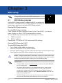
Chapter 3 BIOS setup
3.1 BIOS Setup program .................................................................... 3-1
3.2 Main menu .................................................................................... 3-2
3.2.1 System Date [Day MM/DD/YYYY] .................................. 3-2
3.2.2 System Time [HH:MM:SS] .............................................. 3-2
3.3 Advanced menu ........................................................................... 3-2
3.3.1 PCH-FW Conguration ................................................... 3-2
3.3.2 Trusted Computing ......................................................... 3-3
3.3.3 CPU Conguration .......................................................... 3-4
3.3.4 Graphics Conguration ................................................... 3-5
3.3.5 PCI Express Conguration .............................................. 3-5
3.3.6 AMT Conguration .......................................................... 3-8
3.3.7 CSM Conguration .......................................................... 3-9
3.3.8 Super IO Conguration ................................................... 3-9
3.3.9 Serial Console Redirection ........................................... 3-11
3.3.10 SATA And RST Conguration ....................................... 3-13
3.3.11 Network Stack Conguration ........................................ 3-14
3.3.12 USB Conguration ........................................................ 3-15
3.3.13 NVMe Conguration ...................................................... 3-16

iv
3.3.14 Onboard Devices Conguration .................................... 3-16
3.3.15 EZ-Flash ....................................................................... 3-16
3.3.16 APM Conguration ........................................................ 3-16
3.3.17 Watchdog Timer ............................................................ 3-18
3.3.19 Miscellaneous ............................................................... 3-18
3.4 Hardware Monitor menu ............................................................ 3-18
3.4.1 Smart Fan Mode ........................................................... 3-18
3.5 Security menu ............................................................................ 3-19
3.5.1 Administrator Password ................................................ 3-19
3.5.2 User Password .............................................................. 3-19
3.5.3 Secure Boot .................................................................. 3-20
3.6 Boot menu .................................................................................. 3-20
3.7 Exit menu .................................................................................... 3-21
Appendix
Notices .......................................................................................................A-1
Service and Support .................................................................................A-5

1-1
Chapter 1: General information
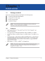
1.1 Package contents
Check your industrial motherboard package for the following items.
1 x ASUS Q470EA-IM-A Motherboard
1 x Serial ATA 6.0 Gb/s cable
3 x M.2 screw packages
1 x ASUS I/O Shield
NOTE: If any of the above items is damaged or missing, contact your
distributor or sales representative immediately.
1.2 Features
• Intel® socket 1200 for 10th Gen Intel® Core™ i9/ i7/ i5/ i3, Pentium®, and
Celeron® processors
• Four Dual Channel DDR4 2933/2666/2400 MHz U-DIMMs up to 128GB
• 6 x SATA 6.0 Gb/s, 4 x USB 3.2 Gen 2, 2 x USB 3.2 Gen 1, 6 x USB 2.0, 6 x
COM
• 2 x PCIe x16 slot, 1 x M.2 (Key E, 2230) for WiFi/BT device, 1 x M.2 (Key M,
2242/2260/2280) with PCIe and SATA modes for SSD, 1 X M.2 B key, type
3042/3052/2260/2280 (PCIe x1/USB 3.2 Gen1/USB 2.0),*type 3042/3052
support 4G/5G module
• Multi-display: 1 x VGA, 1 x HDMITM, 2 x DisplayPorts
NOTE: The system supports up to three displays simultaneously. If all
four display ports are connected, the display priority will be DisplayPort 1 >
DisplayPort 2 > HDMITM > VGA.
Chapter 1
Product overview

Q470EA-IM-A
1-2
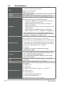
1.3 Specications
(continued on the next page)
CPU
Intel® socket 1200 for 10th Gen Intel® Core™ i9/ i7/ i5/ i3,
Pentium®, and Celeron® processors
Supports Intel® 14nm CPU
Supports up to 125W
Chipset Intel® Q470E Chipset
Memory 4 x U-DIMMs, max. 128GB, DDR4 2933/2666/2400 MHz
Graphics
Integrated graphics processor - Intel® HD Graphics support
Multi-VGA output support: DP/HDMI/VGA ports
- Supports 2 x DisplayPort 1.4a outputs with a maximum
resolution of 4096 x 2160 @60 Hz
- Supports HDMI output with a maximum resolution of
4096 x 2160 @30Hz
- Supports VGA output with a maximum resolution of 1920
x 1200 @60Hz
- Triple Display: VGA+HDMI+DisplayPort / DisplayPort +
HDMI + DisplayPort / VGA + DisplayPort + DisplayPort*
* The system supports up to three displays simultaneously. If
all four display ports are connected, the display priority will be
DisplayPort 1 > DisplayPort 2 > HDMITM > VGA.
Expansion slots
2 x PCI Express 3.0/2.0 x16 slots (1 x16 mode / 2 x8 mode)*
3 x PCI Express 3.0/2.0 x4 slots (x4, x4, x2 mode)
1 x M.2 M Key, type 2242/2260/2280 (PCIe x4 / SATA mode)
1 x M.2 B Key, type 3042/3052/2260/2280 (PCIe x1/USB 3.2
Gen1/USB 2.0), *type 3042/3052 support 4G/5G module
1 x M.2 E Key, type 2230 (PCIe x1 / USB2.0)
1 x SIM slot
* If PCIEX16_2 is occupied, it will be set at 2 x8 mode
automatically by BIOS.
Storage
6 x SATA 3.0 support up to 6.0 Gb/s ports*, RAID 0/1/5/10
* If you install an M.2 PCIe x4 SSD on M.2 M key module, SATA
port 1 and SATA port 2 will be disabled.
* If you install an M.2 SATA SSD on M.2 M key module, SATA
port 2 will be disabled.
LAN Dual Intel® Lan: 1 x Intel® i219LM (1 GbE), 1 x Intel® i225V
(2.5 GbE)
Audio Realtek ALC897 High Denition Audio CODEC
Rear panel I/O ports
1 x VGA port
1 x HDMITM port
2 x DisplayPorts
4 x USB 3.2 Gen 2 ports (3 x Type-A + 1 x Type-C®)
2 x USB 2.0 ports
2 x LAN (RJ45) ports
1 x P/S2 keyboard/mouse combo port
1 x COM port (RS232/422/485)
3 x Audio jacks (Line-Out, Line-In, Mic In)

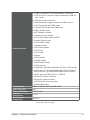
1-3
Chapter 1: General information
Internal I/O ports
5 x COM Port headers (1 x RS232/422/485, 4 x RS232)
1 x USB 3.2 Gen 1 connector supports additional 2 USB 3.2
Gen 1 ports
2 x USB 2.0 vertical connectors
1 x USB 2.0 header supports additional 2 USB 2.0 ports
1 x CPU Fan header with PWM mode
3 x Chassis Fan headers with PWM mode
6 x SATA 6.0Gb/s ports
1 x RTC Battery connector
1 x Chassis Intrusion header
1 x Front Panel Audio header (AAFP)
1 x System Panel header
1 x Clear CMOS header
1 x Speaker header
1 x LPC Debug header
1 x I2C header
1 x LPT header
1 x Buzzer
1 x GPIO header
1 x S/PDIF header
1 x WDT Enable header
1 x TPM connector
1 x M.2 M Key, type 2242/2260/2280 (PCIe x4 / SATA mode)
1 x M.2 B key, type 3042/3052/2260/2280 (PCIe x1/USB 3.2
Gen1/USB 2.0), *type 3042/3052 support 4G/5G module
1 x M.2 E Key, type 2230 (PCIe x1 / USB2.0)
1 x 24-pin ATX power connector
1 x 8-pin ATX power connector
1 x AT/ATX mode selection jumper
1 x Disable ME jumper
Manageability WfM 2.0, DMI 2.0, WOL by PME, GPIO
Watch dog timer Yes
Power requirement AT/ATX mode
Operation
Temperature 0~60°C
Non-Operation
Temperature -40~85°C
(continued on the next page)

Q470EA-IM-A
1-4
NOTE: Specications are subject to change without notice. Please refer to the
ASUS website for the latest specications.
Relative Humidity 15%~95%
OS support
Windows® 10 (64-bit)
Windows® 10 IoT Enterprise
Ubuntu
RedHat Enterprise
Fedora Workstation
OpenSUSE
Certication CE, FCC
Form Factor ATX Form Factor, 9.6”x 12” (24.4cm x 30.5cm)

2-1
Chapter 2: Motherboard information
Chapter 2
Motherboard information
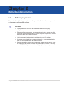
2.1 Before you proceed
Take note of the following precautions before you install motherboard components
or change any motherboard settings.
CAUTION!
• Unplug the power cord from the wall socket before touching any
component.
• Before handling components, use a grounded wrist strap or touch a safely
grounded object or a metal object, such as the power supply case, to avoid
damaging them due to static electricity.
• Hold components by the edges to avoid touching the ICs on them.
• Whenever you uninstall any component, place it on a grounded antistatic
pad or in the bag that came with the component.
• Before you install or remove any component, always remove the AC power
by unplugging the power cord from the power outlet. Failure to do so may
cause severe damage to the motherboard, peripherals, or components.

Q470EA-IM-A
2-2
PCIEX4_1
PCIEX4_2
PCIEX4_3
PCI_2
PCI_1
SPEAKER
SATA6G_4
128Mb
BIOS
SATA6G_3 SATA6G_2 SATA6G_1
CHASSIS
AT_ATX_SEL
SPDIF_OUT
WDT_EN
CLRTC
F_PANEL
USB1011
I2C
BUZZER
M.2(WIFI)
LPT
AAFP
TPM
EATXPWR
CPU_FAN CHA_FAN2
CHA_FAN3
CHA_FAN1
BATTERY
PCIEX16_1
PCIEX16_2
Super
I/O
ASM
1083
ASM1480
ASM1480
ASM1480
ASM1480
ASM1480
ASM1480
ALC
897
24.4cm(9.6in)
LGA1200
Intel®
Q470E
Intel®
I219LM
DDR4 DIMM_A1 (64bit, 288-pin module)
2242
2280 2260 2242
2260 30522280 2242
3042
M.2_PCH_(SKT3)
M.2_PCH_(SKT2)
M.2_PCH_(SOCKET3)
PCIE SATA IRST
X4 V V
DDR4 DIMM_A2 (64bit, 288-pin module)
DDR4 DIMM_B1 (64bit, 288-pin module)
DDR4 DIMM_B2 (64bit, 288-pin module)
AUDIO
KBMS_USB89
COM1
HDMI
LAN1_U32G2_2
U32G2_C1
LAN2_U32G2_34
SATA6G_6
SATA6G_5
COM1_SEL
EATX12V
30.5cm(12in)
USB_INTERNAL_13
U32G1_67
USB_INTERNAL_12
COM2 COM3
COM2_SEL
COM4 COM5 COM6
LPC_DEBUG
DIS_ME
GPIO_CON
DP2
DP1
VGA
NANO_SIM
1 432 65 33
1
1516177
7
28
2
8
3
11
10
9
12
13
14
20 20 2012324 11 18192122
29
26
26
27
25
28
29
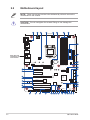
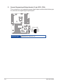
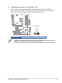
2.2 Motherboard layout
Place this side
towards the rear
of the chassis
NOTE: Place nine screws into the holes indicated by circles to secure the
motherboard to the chassis.
CAUTION! Do not overtighten the screws! Doing so can damage the
motherboard.

2-3
Chapter 2: Motherboard information
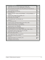
Connectors/Jumpers/Slots Page
1. COM RING/+5V/+12V selection jumper (6-pin COM1_SEL) 2-10
2. EATX Power connectors (24-pin EATXPWR, 8-pin EATX12V) 2-15
3. CPU and Chassis Fan headers (4-pin CPU_FAN, 4-pin CHA_FAN1/2/3) 2-15
4. Intel® LGA1200 CPU socket 2-4
5. M.2 socket 3 (M.2_PCH_(SKT3)) 2-16
6. DDR4 DIMM slots 2-9
7. USB 2.0 connectors / header (USB_INTERNAL_12, USB_INTERNAL_13,
USB1011)
2-16
8. USB 3.2 Gen 1 header (20-1 pin U32G1_67) 2-17
9. M.2 socket 2 (M.2_PCH_(SKT2)) 2-17
10. TPM header (14-1 pin TPM) 2-18
11. SATA 6.0Gb/s ports (7-pin SATA6G_1-6) 2-18
12. M.2 Wi-Fi 2-19
13. I2C header (6-pin I2C) 2-19
14. General Purpose Input/Output header (10-pin GPIO_CON) 2-20
15. System Panel header (10-1 pin F_PANEL) 2-21
16. Chassis Intrusion header (4-1 pin CHASSIS) 2-22
17. Speaker header (4-pin SPEAKER) 2-22
18. Disable ME jumper (3-pin DIS_ME) 2-10
19. LPC Debug header (10-1 pin LPC_DEBUG) 2-23
20. COM Port headers (10-1 pin COM2, COM3, COM4, COM5, COM6) 2-23
21. AT/ATX Mode selection jumper (3-pin AT_ATX_SEL) 2-11
22. WDT Enable jumper (2-pin WDT_EN) 2-11
23. LPT header (26-1 pin LPT) 2-24
24. Front Panel Audio header (10-1 pin AAFP) 2-24
25. Clear CMOS header (2-pin CLRTC) 2-12
26. PCI slots
27. Digital Audio header (4-1 pin SPDIF_OUT) 2-25
28. PCI Express 3.0/2.0 x4 slots
29. PCI Express 3.0/2.0 x16 slots

Q470EA-IM-A
2-4
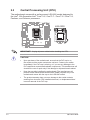
IMPORTANT! Unplug all power cables before installing the CPU.
CAUTION!
• Upon purchase of the motherboard, ensure that the PnP cap is on
the socket and the socket contacts are not bent. Contact your retailer
immediately if the PnP cap is missing, or if you see any damage to the
PnP cap/socket contacts/motherboard components. The manufacturer will
shoulder the cost of repair only if the damage is shipment/transit-related.
• Keep the cap after installing the motherboard. The manufacturer will
process Return Merchandise Authorization (RMA) requests only if the
motherboard comes with the cap on the LGA1200 socket.
• The product warranty does not cover damage to the socket contacts
resulting from incorrect CPU installation/removal, or misplacement/loss/
incorrect removal of the PnP cap.
2.3 Central Processing Unit (CPU)
The motherboard comes with a surface mount LGA1200 socket designed for
the Intel® 10th Generation Intel® Core™ i9 / Core™ i7 / Core™ i5 / Core™ i3,
Pentium®, and Celeron® processors.
LGA1200

2-5
Chapter 2: Motherboard information
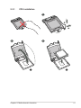
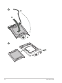
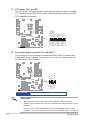
2.3.1 CPU installation
1
A
B
2 3

Q470EA-IM-A
2-6
A
B
C
4
5

2-7
Chapter 2: Motherboard information
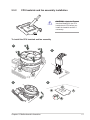
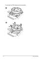
2.3.2 CPU heatsink and fan assembly installation
CAUTION! Apply the Thermal
Interface Material to the CPU
heatsink and CPU before you
install the heatsink and fan if
necessary.
To install the CPU heatsink and fan assembly
B
A
A
B
1
2
3 4

Q470EA-IM-A
2-8
A
B
B
A
To uninstall the CPU heatsink and fan assembly
2
1

2-9
Chapter 2: Motherboard information
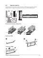
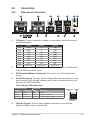
2.4 System memory
This motherboard comes with four Double Data Rate 4 (DDR4) Dual Inline Memory Module
(DIMM) sockets. The gure below illustrates the location of the DDR4 DIMM sockets:
Channel Sockets
Channel A DIMM_A1 & DIMM_A2*
Channel B DIMM_B1 & DIMM_B2*
Installing a DIMM
DIMM_B1
DIMM_B2*
DIMM_A1
DIMM_A2*
Recommendedmemoryconguration
DIMM_A2*
DIMM_A1
DIMM_A2*
DIMM_B2*
DIMM_A2*
DIMM_B1
DIMM_B2*
21
B
A
B
A
To remove a DIMM

Q470EA-IM-A
2-10
2.5 Jumpers
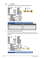
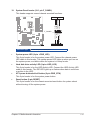
1. COM Ring/+5V/+12V selection jumper (6-pin COM1_SEL)
Setting Pins
+12V 1-2
+5V 3-4
RI (Default) 5-6
RI
(Default)
+5V+12V
COM2_SEL
1
2
3
4
5
6
A
B
B
COM1_SEL
A
Connector type
HEADER 2x3p, 2.54mm pitch, S/T
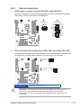
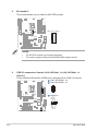
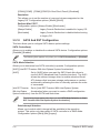
2. Disable ME jumper (3-pin DIS_ME)
This jumper allows you to enable or disable the Intel® ME function. Set this
jumper to pins 1-2 to enable (default) the Intel® ME function and to pins 2-3 to
disable it.
21 2 3
DIS_ME
Disable intel
ME function
Normal
(Default)
Connector type
HEADER 1x3p, 2.54mm pitch, S/T

2-11
Chapter 2: Motherboard information
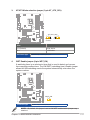
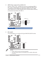
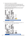
3. AT/ATX Mode selection jumper (3-pin AT_ATX_SEL)
Pins
1-2 (Default) High Avtive
2-3 Low Active
21 2 3
High Active
(Default)
Low Active
AT_ATX_SEL
Connector type
HEADER 1x3p, 2.54mm pitch, S/T
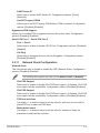
4. WDT Enable jumper (2-pin WDT_EN)
A watchdog timer is an electronic timer that is used to detect and recover
from computer malfunctions. The HW WDT (watchdog timer) Enable jumper
allows the HW watchdog resets the system automatically even when the
system crashes.
WDT_EN
21
NOTE: By default, this jumper is set to HW WDT enabled with a jumper cap
attached.
Connector type
HEADER 1x2p, 2.54mm pitch, S/T

Q470EA-IM-A
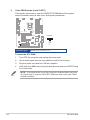
2-12
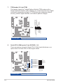
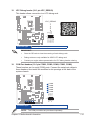
To erase the RTC RAM:
1. Turn OFF the computer and unplug the power cord.
2. Use a metal object such as a screwdriver to short the two pins.
3. Plug the power cord and turn ON the computer.
4. Hold down the <Del> key during the boot process and enter BIOS Setup
to re-enter data.
NOTE: If the steps above do not help, remove the onboard battery and move
the jumper again to clear the CMOS RTC RAM data. After clearing the CMOS,
reinstall the battery.
5. Clear CMOS header (2-pin CLRTC)
This header allows you to clear the CMOS RTC RAM data of the system
setup information such as date, time, and system passwords.
+3V_BAT
GND
CLRTC
PIN 1
Connector type
HEADER 1x2p, 1.25mm pitch, S/T
La pagina si sta caricando...
La pagina si sta caricando...
La pagina si sta caricando...
La pagina si sta caricando...
La pagina si sta caricando...
La pagina si sta caricando...
La pagina si sta caricando...
La pagina si sta caricando...
La pagina si sta caricando...
La pagina si sta caricando...
La pagina si sta caricando...
La pagina si sta caricando...
La pagina si sta caricando...
La pagina si sta caricando...
La pagina si sta caricando...
La pagina si sta caricando...
La pagina si sta caricando...
La pagina si sta caricando...
La pagina si sta caricando...
La pagina si sta caricando...
La pagina si sta caricando...
La pagina si sta caricando...
La pagina si sta caricando...
La pagina si sta caricando...
La pagina si sta caricando...
La pagina si sta caricando...
La pagina si sta caricando...
La pagina si sta caricando...
La pagina si sta caricando...
La pagina si sta caricando...
La pagina si sta caricando...
La pagina si sta caricando...
La pagina si sta caricando...
La pagina si sta caricando...
La pagina si sta caricando...
La pagina si sta caricando...
La pagina si sta caricando...
La pagina si sta caricando...
La pagina si sta caricando...
La pagina si sta caricando...
La pagina si sta caricando...
-
 1
1
-
 2
2
-
 3
3
-
 4
4
-
 5
5
-
 6
6
-
 7
7
-
 8
8
-
 9
9
-
 10
10
-
 11
11
-
 12
12
-
 13
13
-
 14
14
-
 15
15
-
 16
16
-
 17
17
-
 18
18
-
 19
19
-
 20
20
-
 21
21
-
 22
22
-
 23
23
-
 24
24
-
 25
25
-
 26
26
-
 27
27
-
 28
28
-
 29
29
-
 30
30
-
 31
31
-
 32
32
-
 33
33
-
 34
34
-
 35
35
-
 36
36
-
 37
37
-
 38
38
-
 39
39
-
 40
40
-
 41
41
-
 42
42
-
 43
43
-
 44
44
-
 45
45
-
 46
46
-
 47
47
-
 48
48
-
 49
49
-
 50
50
-
 51
51
-
 52
52
-
 53
53
-
 54
54
-
 55
55
-
 56
56
-
 57
57
-
 58
58
-
 59
59
-
 60
60
-
 61
61


Asus Q470EA-IM-A Manuale utente
- Categoria
- Schede madri
- Tipo
- Manuale utente
in altre lingue
- English: Asus Q470EA-IM-A User manual
Documenti correlati
-
Asus N100I-EM-A Manuale utente
-
-
-
-
-
-
-
-
-
Asus ProArt B760-CREATOR Manuale utente