IEI Integration UPC-F12M1-ADLP Manuale utente
- Categoria
- Schede madri
- Tipo
- Manuale utente

UPC-F12M1-ADLP Panel PC
Page I
[MODEL NAME]
User Manual
MODEL:
12.1” Fanless Panel PC with Intel® Core™ i5-1250PE /
Celeron® 7305E CPU, 8GB LPDDR4x RAM, 802.11a/b/g/n/ac/ax
Wi-Fi module
UPC-F12M1-ADLP
Rev. 1.00 - August 28, 2023
User Manual

UPC-F12M1-ADLP Panel PC
Page II
[MODEL NAME]
Revision
Date
Version
Changes
August 28, 2023
1.00
Initial release

UPC-F12M1-ADLP Panel PC
Page III
[MODEL NAME]
Safety Instructions
Warning! Read the user manual before connecting the system to the power
source.
Vorsicht! Bitte lesen Sie die Bedienungsanleitung, bevor Sie das System an eine
Stromquelle anschließen.
Attention! Avant de brancher le système à la source d'alimentation, consultez le
mode d'emploi.
Avvertenza! Consultare il manuale utente prima di collegare il sistema
all'alimentatore.
Atención! Lea atentamente este manual del usuario antes de operar la fuente de
alimentación.
警告!在將系統連接到電源之前,請仔細閱讀使用手冊。
警告!在将系统连接到电源之前,请仔细阅读使用手册。
Warning! To prevent the system from overheating, do not operate it in an area that
exceeds the maximum operating temperature described in the user manual.
Vorsicht! Um eine Überhitzung des Systems zu vermeiden, betreiben Sie es
ausschließlich im zulässigen Betriebstemperaturbereich. Dieser ist in der
Bedienungsanleitung vermerkt.
Attention! Pour éviter la surchauffe du système, ne l'utilisez pas dans une zone
dont la température dépasse les limites décrits dans le mode d'emploi.
Avvertenza! Per evitare che il sistema si surriscaldi, non utilizzarlo in aree che
superino la temperatura massima d'esercizio descritta nel manuale utente.
Atención! Para evitar el excesivo calentamiento del sistema, no opere en las
condiciones de temperatura superior a lo recomendado en este manual del
usuario.
警告!為防止系統過熱,不要在使用手冊上記載的產品工作溫度範圍之外操作此系
統。
警告!为防止系统过热,不要在使用手册上记载的产品工作温度范围之外操作此系
统。

UPC-F12M1-ADLP Panel PC
Page IV
[MODEL NAME]
Warning! Use only the adapter and power cord approved for this system. Use of
another type of adapter may risk fire or explosion. Please refer to the user manual
for the power adapter specifications.
Vorsicht! Nur zugelassene Netzteile und Netzkabel dürfen verwendet werden. Die
Benutzung von anderen Netzteilen kann einen Brand oder eine Explosion zur
Folge haben. Prüfen Sie die jeweiligen Spezifikationen in der
Bedienungsanleitung.
Attention! Utilisez exclusivement le câble d'alimentation et l’adaptateur
homologués pour ce système. L’utilisation d’un autre type d’adaptateur risquerait
de provoquer un incendie ou une explosion. Veuillez référer au mode d'emploi
pour les spécifications de l'adaptateur d'alimentation.
Avvertenza! Utilizzare solo l'adattatore e il cavo di alimentazione approvati per
questo sistema. L'uso di un altro tipo di adattatore può causare rischio d'incendio
o esplosione. Si prega di fare riferimento al manuale utente per le specifiche
sull'alimentazione.
Atención! Utilice solamente el adaptador de corriente alterna (CA) con Marcas
Conformidad otorgadas. Cualquier otro adaptador no otorgado aumenta el riesgo
de explosión o incendio. Por favor consulte el manual del usuario para las
especificaciones del adaptador de alimentación.
警告!只能使用經過認證、適用於本系統的電源變壓器與電源線。使用不適用的電
源變壓器將可能導致火災或爆炸。電源變壓器規格請參考使用手冊。
警告!只能使用经过认证,适用于本系统的电源适配器与电源线。使用不适用的电
源适配器将可能导致火灾或爆炸。电源适配器规格请参考使用手册。
Warning! Ultimate disposal of this product should be handled according to all
national laws and regulations.
Vorsicht! Die Entsorgung dieses Produkts sollte gemäß allen Bestimmungen und
Gesetzen des Landes erfolgen.
Attention! La mise au rebut ou le recyclage de ce produit sont généralement
soumis aux lois et/ou directives de respect de l'environnement. Renseignez-vous
auprès de l'organisme compétent.
Avvertenza! Lo smaltimento di questo prodotto deve essere eseguito secondo le
leggi e i regolamenti locali.
Atención! La disposición final de residuos de este producto se debe cumplir con
las normativas y leyes del país.
警告!本產品的廢棄處理應根據該國家的法律和規章進行。
警告!本产品的废弃处理应根据该国家的法律和规章进行。

UPC-F12M1-ADLP Panel PC
Page V
[MODEL NAME]
Warning! Operation of this equipment in a residential environment could
cause radio interference.
Vorsicht! Der Betrieb dieses Geräts in einer Wohnumgebung kann zu
Funkstörungen führen.
Warning! L'utilisation de cet équipement dans un environnement résidentiel peut
provoquer des interférences radio.
Avvertenza! Il funzionamento di questa apparecchiatura in un ambiente
residenziale potrebbe causare interferenze radio.
Atención! El funcionamiento de este equipo en un entorno residencial podría
causar interferencias de radio.
警告!在住宅環境中操作該設備可能會造成無線電干擾。
警告!在住宅环境中操作该设备可能会造成无线电干扰。

UPC-F12M1-ADLP Panel PC
Page VI
[MODEL NAME]
Copyright
COPYRIGHT NOTICE
The information in this document is subject to change without prior notice in order to
improve reliability, design and function and does not represent a commitment on the part
of the manufacturer.
In no event will the manufacturer be liable for direct, indirect, special, incidental, or
consequential damages arising out of the use or inability to use the product or
documentation, even if advised of the possibility of such damages.
This document contains proprietary information protected by copyright. All rights are
reserved. No part of this manual may be reproduced by any mechanical, electronic, or
other means in any form without prior written permission of the manufacturer.
TRADEMARKS
All registered trademarks and product names mentioned herein are used for identification
purposes only and may be trademarks and/or registered trademarks of their respective
owners.

UPC-F12M1-ADLP Panel PC
Page VII
[MODEL NAME]
Manual Conventions
WARNING
Warnings appear where overlooked details may cause damage to the
equipment or result in personal injury. Warnings should be taken
seriously.
CAUTION
Cautionary messages should be heeded to help reduce the chance of
losing data or damaging the product.
NOTE
These messages inform the reader of essential but non-critical
information. These messages should be read carefully as any directions
or instructions contained therein can help avoid making mistakes.
HOT SURFACE
This symbol indicates a hot surface that should not be touched without
taking care.
RISK OF ELECTRIC SHOCK
This symbol is to identify equipment, for example, the welding power
source, that has risk of electric shock.

UPC-F12M1-ADLP Panel PC
Page VIII
[MODEL NAME]
Table of Contents
1 INTRODUCTION .......................................................................................................... 1
1.1 OVERVIEW.................................................................................................................. 2
1.2 MODEL VARIATIONS ................................................................................................... 3
1.3 FEATURES ................................................................................................................... 3
1.4 FRONT PANEL ............................................................................................................. 4
1.5 REAR PANEL ............................................................................................................... 4
1.6 BOTTOM PANEL .......................................................................................................... 5
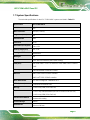
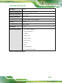
1.7 SYSTEM SPECIFICATIONS ............................................................................................ 6
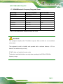
1.7.1 WLAN/Bluetooth Frequency Range and Power ................................................. 8
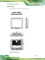
1.8 DIMENSIONS ............................................................................................................... 9
2 UNPACKING ............................................................................................................... 10
2.1 UNPACKING ............................................................................................................... 11
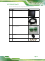
2.2 PACKING LIST ............................................................................................................ 11
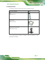
2.3 OPTIONAL ITEMS ...................................................................................................... 13
3 INSTALLATION ......................................................................................................... 14
3.1 ANTI-STATIC PRECAUTIONS ...................................................................................... 15
3.2 INSTALLATION PRECAUTIONS ................................................................................... 16
3.3 SSD INSTALLATION .................................................................................................. 16
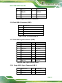
3.4 EXTERNAL I/O CONNECTORS ................................................................................... 19
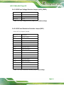
3.4.1 External RS-232 Connector (COM1) ............................................................... 19
3.4.2 External RS-232/422/485 Connector (COM2) ................................................ 19
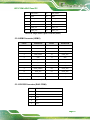
3.4.3 AT/ATX Mode Selection ................................................................................... 20
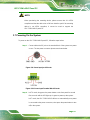
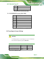
3.5 FERRITE CORE INSTALLATION .................................................................................. 21
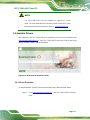
3.6 MOUNTING THE SYSTEM .......................................................................................... 22
3.7 POWERING ON THE SYSTEM ..................................................................................... 23
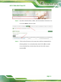
3.8 AVAILABLE DRIVERS ................................................................................................ 24
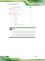
3.8.1 Driver Download ............................................................................................. 24
4 BIOS SETUP ................................................................................................................ 27

UPC-F12M1-ADLP Panel PC
Page IX
[MODEL NAME]
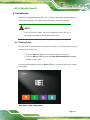
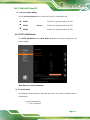
4.1 INTRODUCTION ......................................................................................................... 28
4.1.1 Starting Setup ................................................................................................... 28
4.1.2 Using Setup ...................................................................................................... 29
4.1.3 Getting Help ..................................................................................................... 29
4.1.4 BIOS Menu Bar ................................................................................................ 29
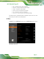
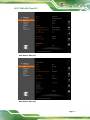
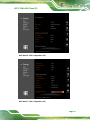
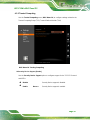
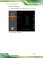
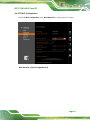
4.2 MAIN ........................................................................................................................ 30
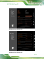
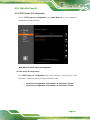
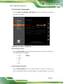
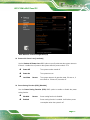
4.3 ADVANCED ............................................................................................................... 34
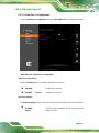
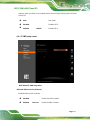
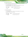
4.3.1 CPU Configuration .......................................................................................... 34
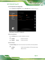
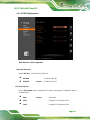
4.3.2 Trusted Computing ........................................................................................... 39
4.3.3 IT5571 Super IO Configuration ....................................................................... 40
4.3.4 IT5571 H/W Monitor ........................................................................................ 43
4.3.5 RTC Wake Settings ........................................................................................... 44
4.3.6 Serial Port Console Redirection ...................................................................... 46
4.3.7 NVMe Configuration ........................................................................................ 47
4.4 CHIPSET ................................................................................................................... 49
4.4.1 System Agent (SA) Configuration .................................................................... 50
4.4.2 PCH-IO Configuration .................................................................................... 56
4.5 SECURITY ................................................................................................................. 63
4.6 BOOT ........................................................................................................................ 64
4.6.1 Boot Configuration .............................................................
错误
!
未定义书签。
4.6.2 Boot Option Priorities ...................................................................................... 65
4.7 SAVE & EXIT ............................................................................................................ 66
5 INTERFACE CONNECTORS ................................................................................... 68
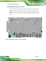
5.1 PERIPHERAL INTERFACE CONNECTORS ..................................................................... 69
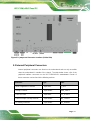
5.2 INTERNAL PERIPHERAL CONNECTORS ...................................................................... 70
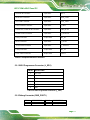
5.2.1 BIOS Programmer Connector (J_SPI1) ......................................................... 71
5.2.2 Debug Connector (DBG_PORT1) ................................................................ 71
5.2.3 EC Programmer Connector (EC_FLASH1) .................................................... 72
5.2.4 Flash Descriptor Security Override (ME_FLASH1) ...................................... 72
5.2.5 EC Debug Connector (EC_DEBUG1) ............................................................. 72
5.2.6 Reset BTN Connector (RST1) ........................................................................ 72
5.2.7 HDD LED Connector (HDD_LED11) ............................................................ 73
5.2.8 CPU FAN Connector (CPU_FAN1) ............................................................... 73
5.2.9 Panel Inverter Connector (J_INV1) ............................................................... 73

UPC-F12M1-ADLP Panel PC
Page X
[MODEL NAME]
5.2.10 Power LED / Power BTN Connector (PWR_BTN1) .................................... 73
5.2.11 Heater Power Connector Connector (J_HEATER1) .................................... 74
5.2.12 B Key Connector (M2_B1) ............................................................................. 74
5.2.13 RFID Connector (J_RFID1) .......................................................................... 75
5.2.14 Touch Panel Connector (J_TOUCH1) ........................................................ 75
5.2.15 E Key Connector (M2_E1) ............................................................................. 76
5.2.16 LVDS Panel Connector (LVDS1) ................................................................. 77
5.3 EXTERNAL INTERFACE PANEL CONNECTORS ............................................................ 78
5.3.1 Power input Connector (PWR1) ...................................................................... 78
5.3.2 Power input Connectors (PWR2) ..................................................................... 79
5.3.3 CAN BUS Connector RJ45(CAN1) ................................................................ 79
5.3.4 CAN BUS Connector RJ45(CAN2) .................................................................. 79
5.3.5 LAN Connector (LAN1/LAN2) ......................................................................... 79
5.3.6 Dual USB2.0 Connector (USB1) ..................................................................... 80
5.3.7 Dual USB 3.2 gen2 Connector (USB2) ............................................................ 80
5.3.8 Single USB 3.2 gen1 Connector (USB 3) ......................................................... 80
5.3.9 HDMI Connector (HDMI1) ............................................................................. 81
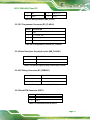
5.3.10 RS232 Connector (RJ45 COM1) .................................................................. 81
5.3.11 RS232/422/485 Connector (RJ45 COM2) .................................................. 82
5.4 PRECONFIGURED JUMPER SETTINGS ......................................................................... 82
5.4.1 LVDS Panel Voltage Selection Jumper (JLCD_PWR1) ................................... 83
5.4.2 LVDS Panel Resolution Selection Jumper (SW1) ............................................ 83

UPC-F12M1-ADLP Panel PC
Page XI
[MODEL NAME]
List of Figures
Figure 1-1: UPC-F12M1-ADLP Panel PC....................................................................................... 2
Figure 1-2: Front View .................................................................................................................... 4
Figure 1-3: Rear Panel .................................................................................................................... 4
Figure 1-4: I/O Panel ....................................................................................................................... 5
Figure 1-5: Dimensions (mm) ........................................................................................................ 9
Figure 3-1: SSD Slot Cover Retention Screws ..........................................................................17
Figure 3-2: Remove SSD Bracket ................................................................................................17
Figure 3-3: Secure the M.2 Module .............................................................................................18
Figure 3-4: AT/ATX Switch Location ...........................................................................................20
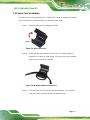
Figure 3-5: Open Ferrite Core ......................................................................................................21
Figure 3-6: Wrapping Cable around the Core ............................................................................21
Figure 3-7: Cable Installed with Ferrite Core .............................................................................22
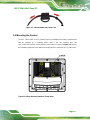
Figure 3-8: VESA Mounting Retention Screw Holes .................................................................22
Figure 3-9: Power Input Jack Pinouts ........................................................................................23
Figure 3-10: Power Input Terminal Block Pinouts ....................................................................23
Figure 3-11: IEI Resource Download Center ..............................................................................24
Figure 5-1: Jumper and Connector Locations (Front Side) .....................................................69
Figure 5-2: Jumper and Connector Locations (Solder Side) ...................................................70

UPC-F12M1-ADLP Panel PC
Page XII
[MODEL NAME]
List of Tables
Table 1-1: Model Variations ........................................................................................................... 3
Table 1-2: System Specifications .................................................................................................. 7
Table 1-3: WLAN/Bluetooth Frequency Range and Power......................................................... 8
Table 3-1: External RS-232 Connector (COM1) Pinouts ...........................................................19
Table 3-2: External RS-232/422/485 Connector (COM2) Pinouts .............................................19
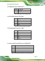
Table 3-3: DB-9 RS-232/422/485 Pinouts ....................................................................................20
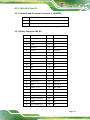
Table 5-1: Peripheral Interface Connectors ...............................................................................71
Table 5-2: BIOS Programmer Connector (J_SPI1) ....................................................................71
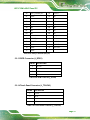
Table 5-3: Debug Connector (DBG_PORT1) ..............................................................................72
Table 5-4: EC Programmer Connector (EC_FLASH1) ...............................................................72
Table 5-5: Flash Descriptor Security Override (ME_FLASH1) .................................................72
Table 5-6: EC Debug Connector (EC_DEBUG1) ........................................................................72
Table 5-7: Reset BTN Connector (RST1) ....................................................................................72
Table 5-8: HDD LED Connector (HDD_LED11) ..........................................................................73
Table 5-9: CPU FAN Connector (CPU_FAN1) ............................................................................73
Table 5-10: Panel Inverter Connector (J_INV1) .........................................................................73
Table 5-11: Power LED / Power BTN Connector (PWR_BTN1) ................................................73
Table 5-12: Heater Power Connector Connector (J_HEATER1) ..............................................74
Table 5-13: B Key Connector (M2_B1)........................................................................................75
Table 5-14: RFID Connector (J_RFID1) .......................................................................................75
Table 5-15: Touch Panel Connector (J_TOUCH1) .....................................................................75
Table 5-16: E Key Connector (M2_E1) ........................................................................................77
Table 5-17: LVDS Panel Connector (LVDS1) .............................................................................77
Table 5-18: Peripheral Interface Connectors .............................................................................78
Table 5-19: PWR Connector (PWR1) Pinouts ............................................................................78
Table 5-20: Power input Connectors (PWR2) Pinouts ..............................................................79
Table 5-21:CAN BUS Connector RJ45(CAN1) ...........................................................................79
Table 5-22:5.3.4 CAN BUS Connector RJ45(CAN2) ..................................................................79
Table 5-23:RJ45 LAN Connector (LAN1/LAN2) .........................................................................80
Table 5-24: USB 2.0 Connector(USB 2.0) ...................................................................................80
Table 5-25: USB 3.2 gen2 Connector ( USB2) ............................................................................80

UPC-F12M1-ADLP Panel PC
Page XIII
[MODEL NAME]
Table 5-26: Single USB 3.2 gen1 Connector (USB 3) ................................................................81
Table 5-27: HDMI Connector (HDMI1) .........................................................................................81
Table 5-28: RS232 Connector (RJ45 COM1) ..............................................................................82
Table 5-29: RS232/422/485 Connector (RJ45 COM2) ................................................................82
Table 5-30: Preconfigured Jumpers ...........................................................................................82
Table 5-31: LVDS Voltage Selection Jumper (JLCD_PWR1) Settings ....................................83
Table 5-32: LVDS Resolution Selection Jumper (SW1) Settings .............................................83

UPC-F12M1-ADLP Panel PC
Page XIV
[MODEL NAME]
List of BIOS Menus
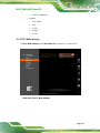
BIOS Menu 1: BIOS Starting Menu .............................................................................................28
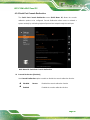
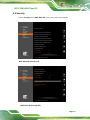
BIOS Menu 2: Main (1/3) ...............................................................................................................30
BIOS Menu 3: Main (2/3) ...............................................................................................................31
BIOS Menu 4: Main (3/3) ...............................................................................................................31
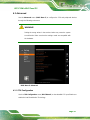
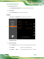
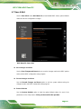
BIOS Menu 5: Advanced ..............................................................................................................34
BIOS Menu 6: CPU Configuration (1/4).......................................................................................35
BIOS Menu 7: CPU Configuration (2/4).......................................................................................35
BIOS Menu 8: CPU Configuration (3/4).......................................................................................36
BIOS Menu 9: CPU Configuration (4/4).......................................................................................36
BIOS Menu 10: Trusting Computing ...........................................................................................39
BIOS Menu 11: IT5571 Super IO Configuration .........................................................................40
BIOS Menu 12: Serial Port 1 Configuration ...............................................................................41
BIOS Menu 13: Serial Port 2 Configuration ...............................................................................42
BIOS Menu 14: IT5571 H/W Monitor ............................................................................................43
BIOS Menu 15: RTC Wake Settings ............................................................................................44
BIOS Menu 16: Serial Port Console Redirection .......................................................................46
BIOS Menu 17: NVMe Configuration ...........................................................................................47
BIOS Menu 18: Chipset ................................................................................................................49
BIOS Menu 19: System Agent (SA) Configuration ....................................................................50
BIOS Menu 20: Memory Configuration .......................................................................................51
BIOS Menu 21: Graphics Configuration .....................................................................................52
BIOS Menu 22: VMD setup menu ................................................................................................53
BIOS Menu 23: PEG Configuration .............................................................................................54
BIOS Menu 24: PCH-IO Configuration(1/2).................................................................................56
BIOS Menu 25: PCH-IO Configuration(2/2).................................................................................57
BIOS Menu 26: PCI Express Configuration ...............................................................................59
BIOS Menu 27: SATA Configuration ...........................................................................................61
BIOS Menu 28: HD Audio Configuration ....................................................................................62
BIOS Menu 29: Security (1/2) .......................................................................................................63
BIOS Menu 30: Security (2/2) .......................................................................................................63

UPC-F12M1-ADLP Panel PC
Page XV
[MODEL NAME]
BIOS Menu 31: Boot .....................................................................................................................64
BIOS Menu 32: Save & Exit ..........................................................................................................66

UPC-F12M1-ADLP Panel PC
Page 1
1 Introduction
Chapter
1

UPC-F12M1-ADLP Panel PC
Page 2
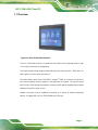
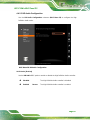
1.1 Overview
Figure 1-1: UPC-F12M1-ADLP Panel PC
The UPC-F12M1-ADLP series is a quad-core Intel® Alder Lake-P powered panel PC with
a rich variety of functions and peripherals.
The aluminum die-casting design and the IP66 enclosure make the UPC-F12M1-ADLP an
ideal system for use in harsh environment.
The Intel® Alder Lake-P Core™ i5-1250PE / Celeron® 7305E is a System-on-Chip (SoC)
that ensures optimal memory, graphics, and peripheral I/O support. The system comes
with 8.0 GB of LPDDR4 onboard memory ensuring smooth data throughputs with reduced
bottlenecks and fast system access.
Multiple connectors ensure simplified connectivity to a variety of external peripheral
devices, including GbE LAN, RS-232/422/485 and USB ports.

UPC-F12M1-ADLP Panel PC
Page 3
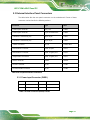
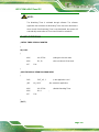
1.2 Model Variations
There are several models in the UPC-F12M1-ADLP series. The model numbers and
model variations are listed below.
Model
Processor
Touchscreen
UPC-F12M1-ADLP-i5/PC/8G-R10
Intel® Alder Lake-P Core™ i5-1250PE
Projected capacitive
UPC-F12M1-ADLP-C/PC/8G-R10
Intel® Alder Lake-P Celeron® 7305E
Projected capacitive
Table 1-1: Model Variations
1.3 Features
The UPC-F12M1-ADLP features are listed below:
12.1" LCD with LED backlight
Flat display screen made of toughened glass with 6H hardness
Projected capacitive type touchscreen
Intel® Alder Lake-P Core™ i5-1250PE or Intel® Alder Lake-P Celeron® 7305E
processor
Preinstalled with dual channel 8GB LPDDR4x on board
Built-in Wi-Fi 802.11a/b/g/n/ax and Bluetooth v5.2
Fanless design
6-sides IP66 protection
9V–36V wide range DC power input

UPC-F12M1-ADLP Panel PC
Page 4
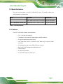
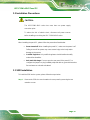
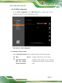
1.4 Front Panel
The front side of the UPC-F12M1-ADLP is a panel with a TFT LCD touchscreen
surrounded by an aluminum die-casting frame (Figure 1-2).
Figure 1-2: Front View
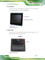
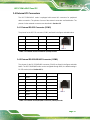
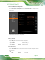
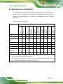
1.5 Rear Panel
The rear panel of the UPC-F12M1-ADLP contains VESA mount screw holes. The rear
panel also provides access for installing M.2 SSD.
Figure 1-3: Rear Panel

UPC-F12M1-ADLP Panel PC
Page 5
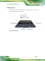
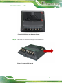
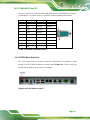
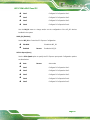
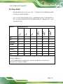
1.6 Bottom Panel
The bottom panel of the UPC-F12M1-ADLP has several I/O interfaces. The I/O cover
must be removed to access the I/O interfaces.
Figure 1-4: Bottom Panel
La pagina si sta caricando...
La pagina si sta caricando...
La pagina si sta caricando...
La pagina si sta caricando...
La pagina si sta caricando...
La pagina si sta caricando...
La pagina si sta caricando...
La pagina si sta caricando...
La pagina si sta caricando...
La pagina si sta caricando...
La pagina si sta caricando...
La pagina si sta caricando...
La pagina si sta caricando...
La pagina si sta caricando...
La pagina si sta caricando...
La pagina si sta caricando...
La pagina si sta caricando...
La pagina si sta caricando...
La pagina si sta caricando...
La pagina si sta caricando...
La pagina si sta caricando...
La pagina si sta caricando...
La pagina si sta caricando...
La pagina si sta caricando...
La pagina si sta caricando...
La pagina si sta caricando...
La pagina si sta caricando...
La pagina si sta caricando...
La pagina si sta caricando...
La pagina si sta caricando...
La pagina si sta caricando...
La pagina si sta caricando...
La pagina si sta caricando...
La pagina si sta caricando...
La pagina si sta caricando...
La pagina si sta caricando...
La pagina si sta caricando...
La pagina si sta caricando...
La pagina si sta caricando...
La pagina si sta caricando...
La pagina si sta caricando...
La pagina si sta caricando...
La pagina si sta caricando...
La pagina si sta caricando...
La pagina si sta caricando...
La pagina si sta caricando...
La pagina si sta caricando...
La pagina si sta caricando...
La pagina si sta caricando...
La pagina si sta caricando...
La pagina si sta caricando...
La pagina si sta caricando...
La pagina si sta caricando...
La pagina si sta caricando...
La pagina si sta caricando...
La pagina si sta caricando...
La pagina si sta caricando...
La pagina si sta caricando...
La pagina si sta caricando...
La pagina si sta caricando...
La pagina si sta caricando...
La pagina si sta caricando...
La pagina si sta caricando...
La pagina si sta caricando...
La pagina si sta caricando...
La pagina si sta caricando...
La pagina si sta caricando...
La pagina si sta caricando...
La pagina si sta caricando...
La pagina si sta caricando...
La pagina si sta caricando...
La pagina si sta caricando...
La pagina si sta caricando...
La pagina si sta caricando...
La pagina si sta caricando...
La pagina si sta caricando...
La pagina si sta caricando...
La pagina si sta caricando...
La pagina si sta caricando...
La pagina si sta caricando...
La pagina si sta caricando...
La pagina si sta caricando...
La pagina si sta caricando...
La pagina si sta caricando...
La pagina si sta caricando...
La pagina si sta caricando...
La pagina si sta caricando...
La pagina si sta caricando...
La pagina si sta caricando...
La pagina si sta caricando...
La pagina si sta caricando...
La pagina si sta caricando...
La pagina si sta caricando...
La pagina si sta caricando...
La pagina si sta caricando...
La pagina si sta caricando...
La pagina si sta caricando...
La pagina si sta caricando...
-
 1
1
-
 2
2
-
 3
3
-
 4
4
-
 5
5
-
 6
6
-
 7
7
-
 8
8
-
 9
9
-
 10
10
-
 11
11
-
 12
12
-
 13
13
-
 14
14
-
 15
15
-
 16
16
-
 17
17
-
 18
18
-
 19
19
-
 20
20
-
 21
21
-
 22
22
-
 23
23
-
 24
24
-
 25
25
-
 26
26
-
 27
27
-
 28
28
-
 29
29
-
 30
30
-
 31
31
-
 32
32
-
 33
33
-
 34
34
-
 35
35
-
 36
36
-
 37
37
-
 38
38
-
 39
39
-
 40
40
-
 41
41
-
 42
42
-
 43
43
-
 44
44
-
 45
45
-
 46
46
-
 47
47
-
 48
48
-
 49
49
-
 50
50
-
 51
51
-
 52
52
-
 53
53
-
 54
54
-
 55
55
-
 56
56
-
 57
57
-
 58
58
-
 59
59
-
 60
60
-
 61
61
-
 62
62
-
 63
63
-
 64
64
-
 65
65
-
 66
66
-
 67
67
-
 68
68
-
 69
69
-
 70
70
-
 71
71
-
 72
72
-
 73
73
-
 74
74
-
 75
75
-
 76
76
-
 77
77
-
 78
78
-
 79
79
-
 80
80
-
 81
81
-
 82
82
-
 83
83
-
 84
84
-
 85
85
-
 86
86
-
 87
87
-
 88
88
-
 89
89
-
 90
90
-
 91
91
-
 92
92
-
 93
93
-
 94
94
-
 95
95
-
 96
96
-
 97
97
-
 98
98
-
 99
99
-
 100
100
-
 101
101
-
 102
102
-
 103
103
-
 104
104
-
 105
105
-
 106
106
-
 107
107
-
 108
108
-
 109
109
-
 110
110
-
 111
111
-
 112
112
-
 113
113
-
 114
114
-
 115
115
-
 116
116
-
 117
117
-
 118
118


IEI Integration UPC-F12M1-ADLP Manuale utente
- Categoria
- Schede madri
- Tipo
- Manuale utente