Seitron DR R02M Thermostat Wireless Kit Manuale utente
- Categoria
- Termostati
- Tipo
- Manuale utente

DRR02M0000SE 039786 110722
1
GENERALITA’
Questo dispositivo e’ un ricevitore a due canali pensato per
l’attivazione di carichi (precisamente valvole elettrotermiche o
circolatori) in sistemi di riscaldamento/raffrescamento via radio
per ambienti domestici o uffici.
Dispone di due canali che devono essere associati a rispettivi
trasmettitori, termostato o cronotermostato via radio. Questo
sistema offre una soluzione ottimale negli edifici dove non è
possibile la stesura di fili tra il termostato e l’ambiente da
controllare. Funzionando sulla frequenza di 868,150 MHz (LPD)
fornisce all’utente tutti i vantaggi di questa banda come la
maggiore libertà da interferenze ed una maggiore efficienza nella
propagazione del segnale.
FUNZIONAMENTO
Ogni termostato o cronotermostato trasmettitore invia determinati
comandi via radio all’unità ricevente in base alla necessità di
riscaldamento o raffreddamento dell’ambiente dove è situato.
Questi comandi via radio vengono quindi ricevuti e decodificati
dall’unità ricevente, che normalmente viene installata nello stesso
locale in cui sono presenti la caldaia o il condizionatore. Nell’unità
ricevente si accende o si spegne il relè di uscita in funzione delle
necessità; le uscite possono essere collegate ad una valvola che
controlla il flusso di acqua calda/fredda nel relativo dispositivo di
riscaldamento/raffreddamento presente nella stanza. Quando e’ in
funzione, il ricevitore verifica continuamente lo stato dei due
canali allo scopo di riconoscere eventuali malfunzionamenti dei
rispettivi trasmettitori.
DESCRIZIONE MECCANICA
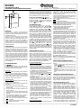
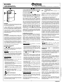
LED ( e in Fig. 1)
Sul pannello frontale del dispositivo sono presenti due LED
multicolore che danno informazioni circa la corretta alimentazione,
lo stato dei relè di uscita e l’intensità del segnale:
Alimentazione
Quando l’unità ricevente viene alimentata, i LED si accendono ed
eseguono una sequenza di lampeggi “verde-rosso-verde-rosso” in
modo da segnalare il buon funzionamento del dispositivo.
Successivamente i LED divengono attivi secondo la loro funzione
normale e il ricevitore inizia a svolgere la sua normale attività
decodificando i segnali emessi dai trasmettitori.
Stato uscite attuatore
Durante il normale funzionamento ognuno dei due LED può
accendersi di colore verde, giallo o rosso.
Il LED fornisce varie informazioni sull’uscita e sul termostato radio
che la pilota.
In generale bisogna tenere presente la seguente regola:
- Il led acceso, qualsiasi sia il colore, indica che la relativa uscita
attuatore è attivata.
- Il led spento o debolmente acceso indica che la relativa uscita
attuatore è disattivata.
- Il colore del led da informazioni riguardo la qualità della
comunicazione radio. Vedere paragrafo "Verifica dell’intensità
del segnale".
- Il LED continuamente lampeggiante indica la presenza di
un’anomalia del sistema che richiede l’intervento dell’utente.
In questo caso il colore del LED ha il seguente significato:
Verde: Errore sulla sonda di temperatura del termostato
trasmettitore.
Giallo: Batteria scarica del termostato trasmettitore.
Rosso: Comunicazione radio assente.
C
Fig. 1
C
A
B
Quando il canale è in stato di anomalia e il LED lampeggia, esso
può lampeggiare in due diversi modi in funzione dello stato del relè
di uscita. Se l’uscita è disattivata il led resta normalmente spento
per poi emettere un breve lampeggio, mentre se l’uscita è attiva il
led resta normalmente acceso per poi spegnersi brevemente.
PULSANTI AUTO-APPRENDIMENTO ( e in Fig. 1)
Il dispositivo ricevitore è dotato di due pulsanti per l’auto-
apprendimento dell’indirizzo al termostato (o cronotermostato),
uno per il canale 1 indicato con in Figura 1 e uno per il canale
2 indicato con in Figura 1.
COLLEGAMENTI ELETTRICI
Il dispositivo può essere alimentato a 230V oppure a 24V . I
morsetti L e N alimentano il ricevitore a 230V e sono da collegare alla
tensione di rete con il neutro sul morsetto N. In alternativa collegare
l’alimentazione ai morsetti a e N per alimentare il ricevitore a 24V .
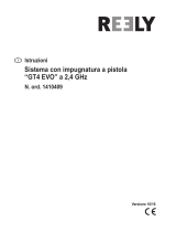
I terminali 1, 2 e 3 sono i contatti, liberi da tensione, tipo SPDT
del relè di uscita relativo al canale 1. I terminali 4, 5 e 6 sono i
contatti, liberi da tensione, tipo SPDT del relè di uscita relativo al
canale 2. In Figura 7 e 9 è illustrato come collegare una valvola che
verrà alimentata quando l’uscita viene attivata e cioè quando il
termostato chiede caldo (riscaldamento) usando il contatto NA del relè.
In Figura 8 e 10 è illustrato come collegare al ricevitore una valvola
caldo e una valvola freddo quando il ricevitore è impostato per eseguire
la regolazione con zona neutra. Le uscite, morsetti da 1 a 6, sono libere
da tensione e isolate con doppio isolamento rispetto al resto del
ricevitore. E’ quindi possibile alimentare il ricevitore a bassa tensione
SELV (24V ) e contemporaneamente pilotare un carico ad alta
tensione (230V ), come visibile in Fig. 9 o 10. In questo caso è
necessario mantenere una separazione tra i cavi SELV 24V e 230V
nel rispetto delle normative vigenti. In particolare è necessario fissare i
gruppi di cavi con delle fascette separando i fili SELV dagli altri per
evitare che se un filo si disconnette accidentalmente questo non riduca
l’isolamento verso SELV.
CONFIGURAZIONE DEL SISTEMA
Per poter installare più termostati nella stessa area e per poter
utilizzare i sistemi multicanale, ogni termostato è dotato di un
codice “indirizzo” proprio. Termostati con indirizzi diversi possono
funzionare contemporaneamente senza interferire e controllare
quindi zone diverse. Allo scopo di memorizzare l’indirizzo del
termostato di cui si vuole ricevere i segnali, è necessario eseguire la
“procedura di auto-apprendimento” di seguito descritta. E’ possibile
ripetere più volte la procedura di auto-apprendimento, il nuovo
indirizzo sovrascriverà quello memorizzato precedentemente.
Procedura di auto-apprendimento
- Alimentare il ricevitore: i LED lampeggiano per qualche secondo
durante la fase di inizializzazione.
- Attivare il modo “test” nel termostato o nel cronotermostato
trasmettitore, il trasmettitore quindi emetterà continuamente un
comando di accensione seguito da uno di spegnimento ogni due
secondi. Attivare il modo “test” in un solo termostato alla volta.
E’ consigliabile tenere il trasmettitore nella stessa stanza del
ricevitore distante almeno un metro da quest’ultimo.
- Premere per un secondo il pulsante di auto-apprendimento del
canale che si intende apprendere ( per il canale 1 e per
il canale 2). In questo modo viene attivata la procedura di “auto-
apprendimento” ed il LED relativo al canale lampeggia
velocemente di color giallo.
- Non appena un comando di test viene ricevuto, il LED rimarrà
acceso giallo fisso e rimarrà in questa condizione per 7 secondi.
In questo tempo il ricevitore continua a ricevere comandi di test,
e ricorda solamente il segnale ricevuto con intensità maggiore.
In questo modo verrà memorizzato il segnale proveniente dal
trasmettitore più vicino e si eviterà di fargli apprendere indirizzi
di eventuali trasmettitori in test estranei al sistema.
- Trascorsi i 7 secondi la procedura si conclude e il LED lampeggia
secondo una sequenza rosso-verde-rosso-verde a indicare
l’avvenuto salvataggio dell’indirizzo del trasmettitore.
- Il ricevitore torna al funzionamento normale, e il relè di uscita del
canale inizierà subito ad attivarsi e disattivarsi ogni due secondi,
seguendo i comandi impartiti dal trasmettitore in modalità “test”.
Con la funzione “test” è consigliato verificare l’intensità del segnale
ricevuto mettendo il trasmettitore nella posizione desiderata.
Non testare più di un trasmettitore allo stesso tempo, per
evitare false indicazioni dovute a sovrapposizioni di segnale.
- Dopo aver verificato che l’intensità del segnale sia
soddisfacente si può procedere con l’installazione definitiva
meccanica ed elettrica.
Verifica dell’intensità del segnale
Il dispositivo visualizza in maniera continua l’intensità del segnale
radio ricevuto per ognuno dei due canali. Ciò semplifica
l’installazione e la messa a punto dell’intero sistema e inoltre
permette di fare una verifica istantanea delle qualità delle
comunicazioni radio di ogni canale.
L’indicazione dell’intensità del segnale è visualizzata da ognuno dei
due LED: essi possono accendersi di colore verde, giallo o rosso a
seconda della qualità del segnale radio ricevuto:
Verde: Il segnale ricevuto è buono o ottimo: comunicazione radio
affidabile.
Giallo: Il segnale ricevuto è sufficiente.
Rosso: Il segnale ricevuto è debole: comunicazione non affidabile.
Lo stato di uscita attuatore spenta è segnalato con il LED
corrispondente debolmente acceso anziché spento. In questo modo
è sempre possibile vedere la qualità del segnale radio.
Il ricevitore visualizza due tipi di qualità del segnale sul LED:
- Analisi immediata dell’ultimo comando ricevuto.
- Analisi a lungo termine dei comandi ricevuti.
Normalmente sul LED viene visualizzata l’analisi “a lungo termine” che
è una valutazione della quantità dei comandi corretti ricevuti nell’arco
degli ultimi 90 minuti di funzionamento. Nel caso in cui nell'arco degli
ultimi 90 minuti non sia stato ricevuto nessun comando dal
trasmettitore, il LED smetterà di indicare l'analisi "a lungo termine" e
visualizzerà l'anomalia "comunicazione radio assente" lampeggiando
rosso. La valutazione viene memorizzata in maniera non-volatile, quindi
è possibile verificare lo stato di comunicazione di ogni canale anche
dopo una mancanza di energia elettrica.
Nell’istante in cui viene ricevuto un comando radio, il LED
dell’uscita viene spento per un breve istante e poi subito riacceso.
Alla riaccensione per un breve istante il LED visualizzerà l’analisi
immediata dell’ultimo comando ricevuto la quale è proporzionale
all’intensità del segnale radio ricevuto. Nel caso in cui il
trasmettitore sia in modo “test”, il LED sul ricevitore visualizzerà
sempre e solo l’analisi “immediata” in modo da poter valutare
immediatamente se si può procedere all’installazione meccanica.
Se l’intensità del segnale non è accettabile provare a cambiare la
posizione del ricevitore o del trasmettitore o eventualmente
valutare la possibilità di installare un dispositivo ripetitore
(DAPF84) il quale raddoppia la portata dei comandi radio.
Ricordare che sia il trasmettitore che il ricevitore devono essere
montati lontano da oggetti metallici o pareti rinforzate con metallo
che potrebbero indebolire i segnali radio.
NOTA: Il LED può lampeggiare a indicare un’anomalia del sistema;
in questo caso il colore del LED ha un significato diverso (vedere il
paragrafo “Stato uscite attuatore”).
CANCELLAZIONE DI UN INDIRIZZO APPRESO
Nel caso in cui si voglia cancellare l’indirizzo appreso su uno dei
due canali:
- Premere e mantenere premuto il pulsante relativo al canale
desiderato ( o Figura 1).
- Il led corrispondente lampeggia velocemente in giallo e dopo
alcuni secondi lampeggerà secondo una sequenza rosso-verde-
rosso-verde.
- Rilasciare il pulsante, il canale ora è inattivo. Quando un canale
è 'inattivo' il relativo LED e relè di uscita resteranno sempre
spenti.
ASSOCIAZIONE CON UN CRONOTERMOSTATO
L’associazione di un canale pilotato da un termostato ad un canale
pilotato da un cronotermostato non è possibile in questo prodotto.
Nel caso uno dei due canali sia pilotato da un cronotermostato, lo
stato Estate/Inverno del cronotermostato verrà esteso anche
all’altro canale nel caso sia pilotato da termostato.
TIPO DI REGOLAZIONE DELL’USCITA
Il ricevitore è configurato di fabbrica per eseguire una regolazione
tramite i relè di uscita di tipo ON/OFF con isteresi predefinita. E’
possibile modificare il tipo di regolazione scegliendo una
regolazione proporzionale di tipo PWM (modulazione a larghezza di
impulso). In generale è possibile configurare il tipo di regolazione
dell’uscita e i parametri associati al tipo di regolazione scelta, per
esempio è possibile modificare l’isteresi della regolazione ON/OFF o
la banda proporzionale della regolazione PWM. Per configurare il
tipo di regolazione è necessario utilizzare un termostato
trasmettitore a display (es.: TRD01B, TRD02B, DCW01B) i quali
possiedono un menù di configurazione in cui è possibile
personalizzare i parametri relativi al tipo di regolazione che verranno
trasmessi al ricevitore e memorizzati durante la procedura di Test.
E’ possibile configurare il tipo di regolazione anche quando si utilizza
un termostato non configurabile (es. DTPF85BC) in questo caso si
può temporaneamente apprendere l’indirizzo e configurare l’uscita
con un termostato configurabile a display, successivamente si
D
D
A B
A
B
A B
A B
- ITALIANO -
C
DR R02M
RICEVITORE RADIO 2 CANALI
PER IMPIANTI DI RISCALDAMENTO/RAFFRESCAMENTO
Via del Commercio, 9/11 36065 Mussolente (VI)
Tel.: +39.0424.567842 - Fax.: +39.0424.567849 - http://www.seitron.it - e-mail: info@seitron.it

DRR02M0000SE 039786 110722
2
apprende il termostato non configurabile dell’installazione definitiva,
il ricevitore memorizza e mantiene la configurazione dell’uscita del
termostato configurabile a display anche quando viene appreso
successivamente un termostato non configurabile.
Nel caso sia stata personalizzata l’uscita e si voglia tornare alla
configurazione ON/OFF di fabbrica è necessario eseguire il reset
default di fabbrica.
RESET DEFAULT DI FABBRICA
La procedura di reset default cancella la memoria non volatile del
dispositivo, eliminando qualsiasi indirizzo appreso con la procedura
di autoapprendimento e riportando a default le configurazioni delle
uscite al tipo ON/OFF con isteresi predefinita.
Per eseguire il reset default di fabbrica:
- Togliere alimentazione.
- Premere e tenere premuti i due pulsanti e .
- Ridare alimentazione.
- Attendere i lampeggi dei LED.
- Rilasciare i pulsanti.
REGOLAZIONE CON ZONA NEUTRA
Il ricevitore può essere impostato per eseguire una regolazione con
zona neutra tramite il jumper JP1 (vedere il punto 7 nel paragrafo
"Installazione").
Quando in regolazione con zona neutra il ricevitore pilota con il relè
del canale 1 la valvola caldo e con il relè del canale 2 la valvola
freddo.
Nella regolazione con zona neutra si potrà apprendere un solo
termostato sul canale 1 e lo stesso termostato piloterà entrambi i
relè del canale 1 e canale 2.
Se la temperatura di setpoint è maggiore della temperatura
ambiente si ha una richiesta di caldo e verrà attivata la valvola
caldo sul relè 1, viceversa se la temperatura di setpoint è minore
della temperatura ambiente si ha una richiesta di freddo e verrà
attivata la valvola freddo sul relè 2. Se la temperatura ambiente
soddisfa la temperatura di setpoint entrambe le uscite rimarranno
spente. Più in dettaglio l’ampiezza della zona neutra determina il
range di temperatura nella quale le uscite rimarranno spente.
L’ampiezza della zona neutra è impostabile sul trimmer con un
piccolo cacciavite nel range 1÷11°C (vedere il punto 8 nel
paragrafo "Installazione").
L’uscita caldo verrà attivata quando la temperatura ambiente è
inferiore alla temperatura di setpoint di metà zona neutra, mentre
l’uscita freddo verrà attivata quando la temperatura ambiente sarà
superiore alla temperatura di setpoint di metà zona neutra.
Quando in regolazione con zona neutra si presuppone che i sistemi
di riscaldamento e raffrescamento siano sempre disponibili e lo
stato Estate/Inverno del trasmettitore verrà ignorato, in quanto è
la temperatura ambiente che determinerà se riscaldare o
raffrescare.
Quando in regolazione con zona neutra la modalità test del
termostato farà commutare ogni 2 sec. solo l'uscita 1 (caldo).
Quando il ricevitore è impostato per regolazione con zona neutra
non è possibile eseguire la limitazione inferiore e superiore della
temperatura del pavimento impostabile sui termostati TRD01B e
DCW01B.
RISOLUZIONE DEI PROBLEMI
SINTOMO: Il ricevitore non dà segni di vita.
PROBABILE CAUSA: Non è presente la tensione di alimentazione.
RIMEDIO: Controllare il collegamento con la tensione di
rete. Normalmente i LED possono rimanere
spenti, ma all’accensione eseguono una
sequenza di lampeggìi “verde-rosso-verde-
rosso” per segnalare il buon funzionamento.
SINTOMO: Uno dei LED del ricevitore lampeggia
continuamente di colore verde.
PROBABILE CAUSA: Il dispositivo segnala un’anomalia perchè ha
rilevato un errore sulla sonda di temperatura
del termostato o cronotermostato
trasmettitore.
RIMEDIO: Verificare la sonda di temperatura del
trasmettitore e l’eventuale jumper di
selezione tra sonda interna ed esterna.
Leggere attentamente le istruzioni dei
trasmettitori per ulteriori informazioni.
SINTOMO: Uno dei LED del ricevitore lampeggia
continuamente di colore giallo.
PROBABILE CAUSA: Il dispositivo segnala un’anomalia perché ha
rilevato batterie scariche sul termostato o
cronotermostato trasmettitore.
RIMEDIO: Sostituire le batterie dei relativi trasmettitori.
Leggere attentamente le istruzioni dei
trasmettitori per ulteriori informazioni.
SINTOMO: Uno dei LED del ricevitore lampeggia
continuamente di colore rosso.
PROBABILE CAUSA: Il canale è in “stato di allarme” perché la
comunicazione radio è assente.
RIMEDIO: Ricontrollare la comunicazione radio con la
funzione “test” sul trasmettitore. Valutare la
possibilità di spostare i dispositivi lontano da
schermi metallici, o di installare un
dispositivo “ripetitore”.
SINTOMO: Quando il trasmettitore sta funzionando in
modo “Test”, il ricevitore non accende il relè.
PROBABILE CAUSA: L’indirizzo del trasmettitore non coincide con
l’indirizzo memorizzato nel ricevitore.
RIMEDIO: Eseguire l’auto-apprendimento come spiegato
nella sezione ”Configurazione del sistema”.
SINTOMO: Avviando la procedura di auto-apprendimento,
il ricevitore non accende il led giallo
lampeggiante.
PROBABILE CAUSA: Sì è premuto il pulsante troppo velocemente.
RIMEDIO: Avviare la procedura di auto-apprendimento
tenendo premuto il pulsante per un secondo.
SINTOMO: Il trasmettitore si trova in modo “test” ma il
ricevitore non attiva nessun relè, i LED non
indicano alcuna ricezione di comandi via
radio.
PROBABILE CAUSA: I segnali ricevuti sono troppo deboli per la
corretta decodifica dei comandi.
RIMEDIO: Valutare la possibilità di spostare i dispositivi
lontano da schermi metallici, o di installare un
dispositivo “ripetitore”.
SINTOMO: Uno dei LED del ricevitore rimane acceso di
colore rosso nonostante la comunicazione con
il termostato trasmettitore sia stata
ripristinata.
PROBABILE CAUSA: L’indicazione della qualità del segnale a lungo
termine ricorda la storia degli ultimi 90 minuti
di funzionamento del canale.
RIMEDIO: Verificare con il modo “test” che la qualità
del segnale immediata sia sufficiente ed
attendere fino a 90 minuti affinchè la
segnalazione a lungo termine torni verde.
CARATTERISTICHE TECNICHE
Alimentazione: 230V 50Hz / 24V
Assorbimento: 11VA
Portata contatti relè:
2x6(4)A 250
V
(liberi da tensione)
Isteresi regolazione: 0,3°C
Frequenza: 868,150 MHz
Sensibilità: -105 dBm
Modulazione: GFSK
Larghezza banda (-3 dB): 100 KHz
Tipo antenna: stilo interno
Max. distanza dal trasmettitore: >300m in campo libero
>50 m all’interno di edifici
(dipendente dall’edificio e
dall’ambiente)
Grado di protezione: IP 3X
Tipo di azione: 1
Categoria di sovratensione: II
Grado di inquinamento: 2
Indice di Tracking (PTI): 175
Classe di protezione contro
le scosse elettriche: II
Tensione impulsiva nominale: 2500V
Numero di cicli automatici: 100000 (schemi Fig. 7, 8, 9, 10)
Classe del software: A
Tensione prove EMC: 230V 50Hz
Corrente prove EMC: 45 mA
Tolleranza distanze esclusione
modo guasto ‘corto’: ±0,15 mm
Temperatura prova sfera: 75 °C
Temperatura funzionamento: 0°C .. 40 °C
Temperatura stoccaggio: -10°C .. +50 °C
Limiti umidità: 20% .. 80 % RH non condensante
Contenitore: Materiale: ABS V0 autoestinguente
Colore: Bianco segnale
(RAL 9003)
Fissaggio: A parete
DIMENSIONI
GARANZIA
Nell’ottica di un continuo sviluppo dei propri prodotti, il costruttore
si riserva il diritto di apportare modifiche a dati tecnici e
prestazioni senza preavviso.
Il consumatore è garantito contro i difetti di conformità del
prodotto secondo la Direttiva Europea 1999/44/CE nonché il
documento sulla politica di garanzia del costruttore.
Su richiesta è disponibile presso il venditore il testo completo della
garanzia.
A B
- ITALIANO -

DRR02M0000SE 039786 110722
3
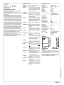
INSTALLAZIONE
Per l'installazione è necessario accedere alle parti interne.
ATTENZIONE!
- Prima di procedere con l’installazione del ricevitore
assicurarsi che i segnali radio trasmessi dai termostati
siano correttamente ricevuti dal ricevitore.
- Collegare l'apparecchio alla rete di alimentazione tramite
un interruttore bipolare conforme alle norme vigenti e con
distanza di apertura dei contatti di almeno 3 mm in
ciascun polo.
- L’alimentatore 24V deve essere dotato di protezione da
sovraccarico.
- L’installazione ed il collegamento elettrico del dispositivo
devono essere eseguiti da personale qualificato ed in
conformità alle leggi vigenti.
- Prima di effettuare qualsiasi collegamento accertarsi che
la rete elettrica sia scollegata.
Assicurarsi che il dispositivo non sia alimentato (che non sia
presente tensione).
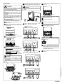
1
Ruotare il coperchio cavi esercitando una leggera pressione
fino ad estrarla completamente (Fig. 3).
3
Fig. 3
Configurare il dispositivo come indicato in "Configurazione
del sistema".
10
Fig. 2
Spingere, con l'aiuto di un cacciavite, la linguetta plastica
situata nella feritoia in basso fino a sollevare leggermente il
coperchio cavi (Fig. 2).
2
Eseguire i collegamenti elettrici seguendo lo schema
appropriato e il paragrafo "Collegamenti elettrici" .
6
: Isolamento rinforzato
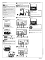
Impostare il jumper JP1 se si desidera la regolazione con
zona neutra.
7
Fig. 11
Impostare il trimmer dell’ampiezza della zona neutra se si è
impostata la regolazione con zona neutra.
8
Fig. 12
Fig. 5
E
F F
Fig. 4
D D
- ITALIANO -
Fig. 7
Posizionare il coperchio cavi sulla base e ruotarlo verso la base;
spingere verso l'interno la linguetta plastica posta sulla parte
inferiore della base ed esercitare una pressione che faccia
scattare la linguetta plastica di fissaggio all'interno del foro sul
lato inferiore del coperchio cavi (Fig. 3).
9
IL JUMPER JP1 PERMETTE DI IMPOSTARE IL MODO DI
FUNZIONAMENTO DEL RICEVITORE:
B
A
B
A
Ricevitore a due canali (default).
Ricevitore a un canale con regolazione zona neutra.
Fig. 8
L’AMPIEZZA DELLA ZONA NEUTRA PUÒ ESSERE
IMPOSTATA, CON L'AIUTO DI UN PICCOLO CACCIAVITE,
NEL RANGE 1÷11°C.
4
L'ingresso cavi può avvenire in tre modi distinti:
Ingresso cavi dal retro: Rimuovere, con l'aiuto di un
cacciavite, il tassello della base, come indicato dalla freccia
in di Fig. 5.
Ingresso cavi laterale: Eliminare con una pinza adatta i denti
in plastica, come indicato dalle frecce in di Fig. 4.
Ingresso cavi dal bordo inferiore della base: Rimuovere, con
l'aiuto di un cacciavite, i tasselli della base, come indicato
dalle frecce in di Fig. 5.
E
F
D
ATTENZIONE
- Quando si lavora con utensili in vicinanza dei fori delle
viti fare attenzione a non danneggiare i circuiti
elettronici interni.
- Il tipo di ingresso cavi scelto e la rimozione di tasselli
plastici potrebbe modificare il grado di protezione IP del
prodotto.
Fig. 6
Fissare la piastra alla parete tramite le due sedi per viti con
interasse 60 mm (utilizzare le viti e/o i tasselli in dotazione) - Fig. 6.
5
ATTENZIONE
- Il ricevitore deve essere installato su una parete o
superficie in modo da rendere inaccessibile il retro del
prodotto.
Fig. 9
Fig. 10

DRR02M0000SE 039786 110722
4
INSTALLATION
To install the device it is necessary to access the internal parts.
WARNING!
- When deciding on a correct position, make sure that the
radio signals transmitted are received correctly by the
receiving unit.
- The appliance must be wired to the electric mains
through a switch capable of disconnecting all poles in
compliance with the current safety standards and with a
contact separation of at least 3 mm in all poles.
- The 24V power unit must be featured with an overload
protection.
- Device installation and electrical connections must be
carried out by qualified personnel and must comply with
the laws in force.
- Before making any connections, make sure the mains
power is disconnected.
Make sure that the device is not powered (no mains power
supply applied).
1
Rotate the cable lid and remove it completely (Fig. 3).
3
Fig. 3
Configure the device as described in the paragraph
“Configuring the system”.
10
Place the cable lid on the base and rotate it towards the
base; push the cable lid until the locking plastic flap springs
into the hole on the lower side of the cable lid (Fig. 3).
9
Fig. 2
Using a screwdriver, push the plastic flap of the bottom slot
and slightly lift the cable lid up (Fig. 2).
2
Set JP1 jumper if the “dead band” regulation is desired.
7
THE JP1 JUMPER ALLOWS TO SET THE WORKING MODE
OF THE RECEIVER:
B
A
B
A
Two channels receiver (default).
One channel receiver with dead band regulation.
Fig. 11
Set the dead band width trimmer if dead band regulation has
been chosen.
8
Fig. 12
Make the electrical connections following the appropriate
diagram and paragraph " Electrical connections ".
6
Reinforced insulation
Fig. 7
Fig. 8
- ENGLISH -
Fig. 5
E
F F
Fig. 4
D D
THE DEAD BAND WIDTH CAN BE SET WITH A SMALL
SCREWDRIVER IN THE RANGE 1÷11°C .
Fix the plate onto the wall using the two screws housings
with a 60 mm centre-to-centre distance (use the screws
and/or dowels supplied) - Fig. 6.
5
Fig. 6
WARNING
- The receiver must be installed on a wall or on a surface
in order to make the back of the product inaccessible.
4
There are three options for the cable entry:
Back cable entry: Open the hole Fig. 5, with a
screwdriver.
Side cable entry: With suitable pliers, remove the plastic
teeth, as indicated by arrows in Fig. 4.
Bottom cable entry: Open one or both holes Fig. 5, with
a screwdriver.
E
F
D
WARNING
- When working with tools in the vicinity of the screw
holes, be careful not to damage the internal electronic
circuits.
- The chosen cable entry and the removal of plastic teeth
may modify the IP grade of the product.
Fig. 9
Fig. 10

DRR02M0000SE 039786 110722
5
OVERVIEW
This device is a two channels receiver designed to switch on loads
(more precisely, electro-thermal valves or circulators) via radio in
home or office heating/cooling systems.
It has two channels that have to be associated to relevant
transmitters, wireless thermostat or programmable thermostat.
This system is an optimal solution for buildings in which wires
cannot be laid between thermostats and the environment to be
controlled. Operating on a frequency of 868.150 MHz (LPD)
provides the user with all the advantages of this band, such as the
greatest freedom from interference and greater efficiency in the
transmission of the signal.
OPERATION
Each thermostat or programmable thermostat transmitter sends
radio commands to the receiving unit based on the heating and
cooling requirements of the room where it is located. These radio
commands are then received and decoded by the receiving unit,
which is usually installed in the same room as the boiler or air
conditioning equipment. The relay outputs are turned on or off in
the receiving unit depending on the requirements. These output s
can be connected to valves that control the flow of hot/cold water
in the heating/cooling unit located in the room. While it is
operating, the receiver continuously monitors the status of each
channel in order to detect any transmitter malfunctions.
MECHANICAL DESCRIPTION
LEDs ( and Fig. 1)
On the front panel of the device there are two multicolor LED
which gives information regarding the correct power supply, the
output relays status and the signal strength:
Power supply
When the receiving unit is powered, the LEDs light up and perform
a blinking sequence “green-red-green-red” to indicate the correct
operation of the device. Then the LEDs becomes active depending
on their normal operation and the receiver starts to perform its
normal activity, decoding the signals sent by the transmitters.
Actuator outputs status
During normal operation, each of the LEDs may light up green,
yellow or red.
The LED provides several information about the output and the
wireless thermostat controlling it.
In general, the following rule should be borne in mind:
- When the LED is lit, regardless of its colour, it means that the
corresponding actuator output is ON.
- When the LED is either off or only faintly lit, it means that the
corresponding actuator output is OFF.
- The colour of the LED provides information about the quality of
radio communication. See paragraph on “Checking the signal
strength”.
- When the LED is continuously blinking it indicates a fault in the
system which requires the user‘s intervention. In this case the
colour of the LED has the following meaning:
Green: Error in the temperature probe of the wireless
thermostat.
Yellow: Wireless thermostat battery low
Red: Absence of radio communication.
When the channel is in a fault status and the LED is blinking, it
may blink in two different ways depending on the output relay
status.
If the output is inactive the LED will normally remain off but then
emit a short flash, whereas if the output is active, the LED will
normally remain lit and then go off briefly.
C
SELF-LEARNING BUTTONS ( and Fig. 1)
The device is equipped with two self-learning buttons for setting
up the wireless link between the thermostat (or programmable
thermostat) and the receiver, one button for channel 1 Fig. 1
and one button for channel 2 Fig. 1.
ELECTRICAL CONNECTIONS
The device can be powered at 230V or 24V . Terminals L and
N supply the receiver at 230V and must be connected to mains
with neutral to terminal N. Alternatively connect the power supply
to terminals a and N to power the device at 24V . Terminals 1, 2
and 3 are the voltage free SPDT relay contacts of the channel 1
output. Terminals 4, 5 and 6 are the voltage free SPDT relay
contacts of the channel 2 output. Figure 7 and 9 shows how to
connect a valve that will be powered when the output is set and
that is when the thermostat calls for heat (heating) using the NO
contact of the relay. Figure 8 and 10 shows how to connect to
the receiver a heat valve and a cold valve when the receiver is set
for regulation with dead band. The outputs, terminals 1 to 6, are
voltage free and insulated with reinforced insulation towards the
other circuits of the receiver. Therefore, the receiver can be
supplied with SELV low voltage (24V ), while controlling a high
voltage load (230V ), as shown in Fig. 9 or 10. In this case 24V
SELV and 230V
cables must be separated complying with current
standards. In particular, it is necessary to secure the two groups of
cables with cable ties separating the SELV wires from the others.
This is required to avoid that the insulation to SELV is reduced in the
event of a wire accidentally disconnects.
CONFIGURING THE SYSTEM
To be able to install several thermostats in the same area and to
be able to use the multichannel systems, every thermostat is
equipped with its own address code. Thermostats with different
addresses can work at the same time without interfering each
other and therefore controlling different areas. To memorize the
address of the thermostat from which we want to receive the
signals in the receiver, it is necessary to perform the self-learning
procedure described below. It is possible to repeat several times
the self-learning procedure, the new address will overwrite the old
one stored.
Self-learning procedure
- Switch on the receiver: the LEDs blink for a few seconds
during the initialisation phase.
- Turn on the thermostat or programmable thermostat in “test”
mode, then the transmitter will continuously send an ON
command followed by an OFF command after two seconds.
Turn on only one thermostat in the “test” mode at a time. It is
advisable to keep the transmitter in the same room of the
receiver, apart at least one meter each other.
- Press the self-learning button of the desired channel for a
second Fig.1 for channel 1 and Fig.1 for channel 2. The
self -learning procedure starts: the relevant channel’s LED will
blink quickly yellow.
- As soon as a test command is received, the LED will remain
steadily lit yellow for 7 seconds. During this time the receiver
will continue to receive test commands and memorize only the
signal received with the highest strength. This means that it
will memorize the signal coming from the nearest transmitter
and will thus avoid learning addresses from any transmitters in
test mode which are not meant to be associated to the system.
- After 7 seconds the procedure ends and the LED flashes red-
green-red-green in sequence to indicate that the transmitter
address has been saved.
- The receiver will resume normal operation and the channel
output relay will immediately start to switch ON and OFF every
two seconds following the commands emitted by the
transmitter in “test” mode.
- When using the “test” function it is advisable to check the
strength of the signal received placing the transmitter in the
desired position. To avoid wrong indications due to overlapping
signals, do not test more than one transmitter at a time.
- After verifying that the signal strength is satisfactory, you may
proceed with the final mechanical and electrical installation.
Checking the signal strength
The device constantly indicates the strength of the radio signal
received for each of the two channels. This makes the whole
system simpler to install and regulate; moreover it allows the user
to carry out an instant check on the quality of the radio
communications of each channel.
The signal strength is indicated by each of the two LEDs.
They may light up green, yellow or red according to the quality of
the radio signal received.
Green: The signal received is good or excellent, radio
communication is reliable.
Yellow: The signal received is sufficient.
Red: The signal received is weak, communication is not
reliable.
The status of the output of the actuator that is currently
switched off is signalled with the corresponding LED faintly lit
rather than off, so that the quality of the radio signal can always
be seen.
The receiver indicates two types of signal quality on the LED:
- An immediate analysis of the last command received;
- A long-term analysis of the commands received.
The LED will normally indicate the “long-term” signal quality, based
on the quantity of correct commands received over the previous 90
minutes of operation. In case no command has been received from
the transmitter in the last 90 minutes, the LED will stop showing
the "long-term" analysis and will blink red to show the "absence
of radio communication" fault condition. The signal quality
analysis is non-volatile memorized, so it is possible to evaluate the
channel communication status also after a power cycle. In the
moment a radio command is received, the output LED goes off for
a brief instant and then immediately back on again. For a brief
instant the LED will provide an immediate indication of the last
command received, proportional to the strength of the radio signal
received. If a transmitter is in the “test” mode, the LED on the
receiver will always provide only an “immediate” indication so that
you can instantly assess whether to go ahead with mechanical
installation. If the signal strength is not acceptable try to change
the position of the receiver or transmitter or evaluate the
possibility to install a repeater device (DAPF84) which doubles the
range of the radio commands. Remember that both the transmitter
and receiver must be installed away from metal objects or metal-
reinforced walls that could weaken the radio signals.
NOTE: The LED may blink to signal a system fault. In this case
the colour of the LED has a different meaning, see the paragraph
on “Actuator outputs status”.
DELETION OF A LEARNED ADDRESS
In case you want to delete the address learned on one of the two
channels:
-
Press and hold the button of the desired channel
( or Figure 1).
- The relevant LED flashes quickly in yellow and after a few seconds
will flash in a sequence red-green-red-green.
- Release the button, the channel is now inactive. When a channel is
'inactive' on its LED and relay output will remain permanently off.
ASSOCIATION WITH A PROGRAMMABLE
THERMOSTAT
The association of a channel driven by a thermostat to a channel
driven by a programmable thermostat is not possible in this product.
If one of the channels is controlled by a programmable thermostat,
the heating/cooling setting of the programmable thermostat will be
extended to the other channel if it is controlled by thermostat.
OUTPUT REGULATION TYPE
The receiver is factory configured to perform an ON/OFF type
regulation on the output relays with predefined hysteresis. It is
possible to modify the type of regulation choosing a PWM (pulse
width modulation) proportional regulation.
In general you can configure the type of regulation and the
parameters associated with the type of regulation chosen, e.g.
you can change the hysteresis of the ON/OFF regulation or you
can change the proportional band of the PWM regulation.
To configure the type of regulation you need to use a display
thermostat transmitter (i.e. TRD01B, TRD02B, DCW01B) which
features a configuration menu where you can customize the
regulation parameters that will be transmitted to the receiver and
stored during the "test" mode procedure.
It is possible to configure the type of regulation even when using a
non configurable thermostat (i.e. DTPF85BC) in this case you have
to temporarily learn the address and configure the output with a
display thermostat, then you learn the address of the final non
configurable thermostat.
The receiver maintains the output configuration of the display
thermostat even when a new non configurable thermostat is
learned. In case you have customized the output and you want to
return to the factory default ON/OFF configuration it is necessary
to do a factory default reset.
FACTORY DEFAULT RESET
A factory default reset clears the non-volatile memory of the
device deleting any address learned with the self-learning
procedure and restoring the default ON/OFF output configuration
with predefined hysteresis.
D
A
B
A B
A B
Fig. 1
C
A
B D
A B
- ENGLISH -
DR R02M
2 RADIO CHANNELS RECEIVER
FOR HEATING/COOLING SYSTEM
Via del Commercio, 9/11 36065 Mussolente (VI)
Tel.: +39.0424.567842 - Fax.: +39.0424.567849 - http://www.seitron.it - e-mail: info@seitron.it

DRR02M0000SE 039786 110722
6
To factory reset:
- Power down
- Press and hold both buttons
and Fig.1
- Power on
- Wait until the LEDs blink
- Release the buttons
REGULATION WITH DEAD BAND
The receiver can be set on jumper JP1 to regulate with dead band
(see step 7 under "Installation").
When regulating with dead band, the receiver drives the “heat”
valve with the relay of channel 1 and the “cool” valve with the
relay of channel 2.
When regulating with dead band, the receiver can learn only one
thermostat on channel 1 and the thermostat will drive both relays
of channel 1 and channel 2. If the setpoint temperature is greater
than the room temperature there is a “heating” request and the
“heat” valve on relay 1 will be turned on, conversely, if the
setpoint temperature is lower than the room temperature there is
a “cooling” request and the “cool” valve on relay 2 will be turned
on. If the room temperature matches the setpoint temperature
both outputs remain off. More in detail the width of the dead band
determines the temperature range in which the outputs remain
off. The dead band‘s width can be set on the trimmer with a small
screwdriver in the range 1 to 11 °C (see step 8 in "Installation").
The heating output will be activated when the room temperature
is below the setpoint temperature of half the dead band, while the
cool output will be activated when the room temperature will be
higher than the temperature setpoint of half the dead band.
When in dead band regulation it is assumed that the heating and
cooling systems are always available and the heating/cooling
status of the transmitter will be ignored, as it is the room
temperature that will determine whether to heat or to cool.
When in dead band regulation, the “test” mode of the thermostat
will toggle every 2 seconds only output 1 (heating).
When the receiver is set for dead band regulation, it can not
perform the lower and upper floor temperature limitation that can
be set on TRD01B and DCW01B thermostats.
TROUBLESHOOTING
SYMPTOM: The receiver appears completely “dead”.
PROBABLE CAUSE: There’s no mains power.
REMEDY: Check the mains power connection.
Usually LEDs may remain off, but they
perform a blinking sequence “green-red-
green-red” when the receiver is switched on
to indicate correct operation.
SYMPTOM: One of receiver’s LED continuously blinks
green.
PROBABLE CAUSE: The device is signalling a fault because it
has detected an error in the temperature
probe of the wireless thermostat or
programmable thermostat.
REMEDY: Check the temperature probe of the
transmitter and, if present, the jumper for
selecting between the internal and external
probe. Carefully read the instructions of the
transmitters for further information.
SYMPTOM: One of receiver’s LED continuously blinks
yellow.
PROBABLE CAUSE: The device is signalling a fault because it
has detected the wireless thermostat or
programmable thermostat batteries to be
running low.
REMEDY: Replace the batteries of the transmitters
concerned. Carefully read the instructions of
the transmitters for further information.
SYMPTOM: One of receiver’s LED continuously blinks
red.
PROBABLE CAUSE: The channels in question are in an “alarm
status” due to the absence of radio
communication.
REMEDY: Check the radio communication again using
the “test” function on the transmitter.
Assess whether the devices need to be
moved away from metal shields or a
“repeater” needs to be installed.
SYMPTOM: When starting the self-learning procedure,
the receiver does not blinks the LED yellow.
PROBABLE CAUSE: The self-learning button has been pressed
too quickly.
REMEDY: Start the self-learning procedure keeping
pressed the self-learning button for one
second.
SYMPTOM: The transmitter is in the “test” mode but
the receiver fails to switch on any relay.
The LED does not indicate any reception of
commands via radio.
PROBABLE CAUSE: The signals received are too weak to enable
correct decoding of the commands .
REMEDY: Assess whether the devices need to be
moved away from metal shields or a
“repeater” needs to be installed.
SYMPTOM: The receiver’s LED remain red despite the
communication with the transmitter had
been restored.
PROBABLE CAUSE: The long-term analysis of the signal quality
reports the history of the last 90 minutes of
the channel activity.
REMEDY: Verify with the “test” mode that the
“immediate” indication on the LED indicates
a sufficient signal quality and allow up to
90 minutes for the long-term analysis to
turn green.
TECHNICAL FEATURES
Power supply: 230V 50Hz / 24V
Absorption: 11VA
Relay contacts ratings: 2 x 6(4)A 250V (voltage free)
Regulation hysteresis : 0,3°C
Frequency: 868,150 MHz
Sensitivity: -105 dBm
Modulation: GFSK
Bandwidth (-3 dB): 100 KHz
Type of antenna: internal stylus
Max. distance from transmitter: >300m in free field
>50 m in buildings (depending
on the building and environment)
Protection rating: IP 3X
Type of action: 1
Overvoltage category: II
Pollution degree: 2
Tracking index (PTI): 175
Class of protection
against electric shock: II
Rated impulse voltage: 2500V
Number of automatic cycles: 100000 (diagrams on Fig. 7, 8,
9, 10)
Software class: A
EMC test voltage: 230V 50Hz
EMC test current: 45 mA
Distances tolerances fault
mode ‘short’ exclusion: ±0,15 mm
Ball pressure test temperature: 75 °C
Operating temperature: 0°C .. 40 °C
Storage temperature: -10°C .. +50 °C
Humidity limits: 20% .. 80 % RH non-condensing
Enclosure: Material: ABS V0 self-extinguishing
Colour: Signal White (RAL 9003)
(RAL 9003)
Installation: Wall mounted
DIMENSIONS
WARRANTY
In the view of a constant development of their products, the
manufacturer reserves the right for changing technical data and
features without prior notice.
The consumer is guaranteed against any lack of conformity
according to the European Directive 1999/44/EC as well as to the
manufacturer’s document about the warranty policy. The full text
of warranty is available on request from the seller.
- ENGLISH -
A B
-
 1
1
-
 2
2
-
 3
3
-
 4
4
-
 5
5
-
 6
6


Seitron DR R02M Thermostat Wireless Kit Manuale utente
- Categoria
- Termostati
- Tipo
- Manuale utente
in altre lingue
Documenti correlati
Altri documenti
-
Omega UWTC/UWRTD Manuale del proprietario
-
Vemer RX4-8A Manuale utente
-
 Reely 1410409 Istruzioni per l'uso
-
Telcoma Tango SW and Bleu Manuale del proprietario
-
Eurotherm 3504, 3508 Manuale del proprietario
-
Elvox ESK4 Guida d'installazione
-
Nice FLOXB2R Manuale del proprietario
-
CAME CP Guida d'installazione
-
-
CAME PROXINET, PXC48-96-200 Guida d'installazione
