
RDS
REMOTE DISPLAY
RDS 1520
Manuale d'uso
PANNELLO REMOTO RDS 1520
User's Manual
REMOTE DISPLAY RDS 1520
Manuel de l'utilisateur
TABLEAU À DISTANCE RDS 1520
Benutzerhandbuch
FERNBEDIENUNGSTAFEL RDS 1520
Manual del usuario
PANEL REMOTO RDS 1520
High
Quality
Nautical
Equipment
REV 003A
IT
GB
FR
DE
ES


3
RDS 1520 - REV003A
Pag. 4 Caratteristiche e Installazione
Pag. 5 Installazione: installazione a pannello
Pag. 6 Funzionamento: collegamento elettrico - schema di collegamento
Pag. 7 Funzionamento: attivazione terminatori
Pag. 8 Funzionamento: configurazione dello strumento
Pag. 9 Funzionamento: pannello di controllo - Dati tecnici
Pag. 10 Characteristics and Installation
Pag. 11 Installation: panel installation
Pag. 12 Operation: electric connections
Pag. 13 Operation: activating the terminators
Pag. 14 Operation: setting up the instrument
Pag. 15 Operation: control panel - Technical data
Pág. 28 Características e Instalación
Pág. 29 Instalación: instalación sobre el panel
Pág. 30 Funcionamiento: conexión eléctrica - esquema de conexión
Pág. 31 Funcionamiento: activación de los terminales
Pág. 32 Funcionamiento: configuración del instrumento
Pág. 33 Funcionamiento: panel de control - Especificaciones tecnicas
INDICE
INDEX
SOMMAIRE
INHALTSANGABE
INDICE
Pag. 16 Caractéristiques et Installation
Pag. 17 Installation: intallation sur panneau
Pag. 18 Fonctionnement: branchement electrique
Pag. 19 Fonctionnement: activation des terminaux
Pag. 20 Fonctionnement: configuration de l'instrument
Pag. 21 Fonctionnement: tableau de contrôle - Caractéristiques techniques
Seite 22 Eigenschaften und Installation
Seite 23 Installation: Installierung an der tafel
Seite 24 Betrieb: Stromanschluss
Seite 25 Betrieb: Aktivierung der terminatoren
Seite 26 Betrieb: Konfiguration des gerätes
Seite 27 Betrieb: Bedienungs Display - Technische Daten
IT
GB
FR
DE
ES

4
CARATTERISTICHE TECNICHE
RDS 1520 - REV003A
IT
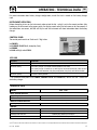
RDS 1520
Il pannello remoto RDS 1520 è uno strumento che permette di monitorare lo stato dei caricabatterie SBC ADV
PLUS medium e high power, tramite l'interfaccia CAN BUS.
INSTALLAZIONE
PRIMA DI UTILIZZARE LO STRUMENTO, LEGGERE ATTENTAMENTE IL PRESENTE MANUALE
D'USO. IN CASO DI DUBBI CONTATTARE IL RIVENDITORE O IL SERVIZIO CLIENTI QUICK
®
.
In caso di discordanze o eventuali errori tra il testo tradotto e quello originario in italiano, fare riferimento
al testo italiano o inglese.
Questo dispositivo è stato progettato e realizzato per essere utilizzato su imbarcazioni da diporto.
Non è consentito un utilizzo differente senza autorizzazione scritta da parte della società Quick
®
.
Il pannello remoto RDS 1520 Quick
®
è stato progettato per gli scopi descritti in questo manuale d'uso. La
società Quick
®
non si assume alcuna responsabilità per danni diretti o indiretti causati da un uso improprio
dell'apparecchio, da un'errata installazione o da possibili errori presenti in questo manuale.
LA MANOMISSIONE DELLO STRUMENTO DA PARTE DI PERSONALE NON AUTORIZZATO FA
DECADERE LA GARANZIA.
LA CONFEZIONE CONTIENE:
RDS 1520 - dima di foratura - cavo di collegamento - condizioni di garanzia - il
presente manuale d'uso.
INSTALLAZIONE DELLO STRUMENTO
Di seguito sarà descritta una procedura di installazione tipica.
Non è possibile descrivere una procedura che sia applicabile a tutte le situazioni.
Adattare questa procedura per soddisfare i propri requisiti.
Individuare la posizione più adatta dove praticare la sede per alloggiare lo strumento seguendo questi criteri:
• Lo strumento deve essere posizionato in modo che sia facilmente leggibile dall'operatore.
• Scegliere una posizione che sia pulita, liscia e piana.
• Deve essere presente un accesso posteriore per l'installazione e la manutenzione.
• Deve esistere spazio sufficiente dietro alla posizione scelta per collocare il retro dello strumento e i connettori.
• La parte posteriore dello strumento deve essere protetta dal contatto con acqua o umidità.
• Porre particolare attenzione quando si effettuano i fori sui pannelli o su parti dell'imbarcazione. Questi fori non
devono indebolire o causare rotture alla struttura dell'imbarcazione.
Lo strumento risponde agli standard EMC (compatibilità elettromagnetica) ma è richiesta una corretta
installazione per non compromettere le proprie prestazioni e quelle degli strumenti posti nelle vicinanze.
Per questo motivo lo strumento deve essere distante almeno:
• 25 cm dalla bussola.
• 50 cm da un qualsiasi apparecchio radio ricevente.
• 1 m da qualsiasi apparato radiotrasmittente (escluso SSB).
• 2 m da qualsiasi apparato radiotrasmittente SSB.
• 2 m dal percorso del fascio radar.
F
F

5
INSTALLAZIONE
RDS 1520 - REV003A
IT
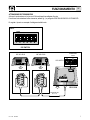
STATUS
POWER
BULK
ABSORPTION
FLOAT
ERROR
LINK
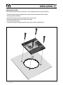
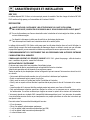
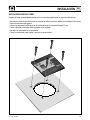
INSTALLAZIONE A PANNELLO
Dopo aver scelto dove posizionare lo strumento, procedere come riportato di seguito:
• Posizionare la dima di foratura (fornita in dotazione) sulla superficie dove sarà installato lo strumento.
• Marcare il centro di ogni foro.
• Realizzare il foro per il retro dello strumento con una fresa diametro 57 mm.
• Rimuovere la dima ed eventuali bave presenti sui fori.
• Inserire lo strumento nella sede.
• Fissare lo strumento al pannello tramite 4 viti (non in dotazione).

6
RDS 1520 - REV003A
IT
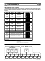
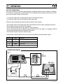
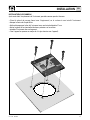
POSIZIONE
1
2
3
4
SEGNALE
+
-
CANH
CANL
Positivo alimentazione strumento
Negativo alimentazione strumento
Interfaccia CAN
Interfaccia CAN
DESCRIZIONE
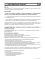
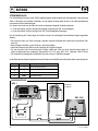
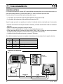
COLLEGAMENTO ELETTRICO
Lo strumento risponde agli standard EMC (compatibilità elettromagnetica) ma è richiesta una corretta installa-
zione per non compromettere le proprie prestazioni e quelle degli strumenti posti nelle vicinanze.
Per questo motivo i cavi dello strumento devono essere distanti almeno:
• 1 m dai cavi che trasportano segnale radio (escluso di radiotrasmittenti SSB).
• 2 m dai cavi che trasportano segnale radio di radiotrasmittenti SSB.
Seguire le regole riportate di seguito per la realizzazione dell'impianto elettrico relativo allo strumento:
• Alimentare lo strumento solo dopo aver effettuato e verificato l'esattezza di tutti i collegamenti elettrici.
• Inserire un interruttore per accendere e spegnere l'apparecchio.
• Inserire un fusibile rapido da 200 mA sulla linea di alimentazione dello strumento.
• Utilizzare come collegamento dell'interfaccia dati (segnali CANH e CANL) un cavo non schermato con una
coppia intrecciata (sezione 0.25/ 0.35 mm
2
AWG 22/24, impedenza 100/150 ohm).
• La lunghezza massima totale del cavo dati deve essere non superiore a 100 metri.
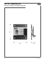
Sul retro dello strumento è presente una morsettiera per i vari collegamenti dei segnali elettrici:
ON
123456
1234
BATTERIA
12V / 24V
INTERRUTTORE FUSIBILE
RDS 1520
SBC ADV PLUS
CONNETTORE
A VASCHETTA
A 9 POLI DB9
SCHEMA DI COLLEGAMENTO
FIG. 1
FUNZIONAMENTO

7
RDS 1520 - REV003A
IT
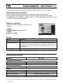
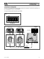
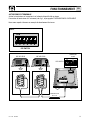
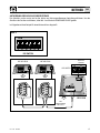
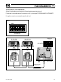
ATTIVAZIONE DEI TERMINATORI
Attivare la terminazione sul primo e sull'ultimo dispositivo collegato alla rete.
Per attivare la terminazione sullo strumento, vedere fig. 2, e paragrafo CONFIGURAZIONE DELLO STRUMENTO.
Di seguito si riporta un esempio di collegamento della rete:
ON
123456
FIG. 2
DIP-SWITCH
ON
123456
1234
ON
123456
DB9 TERMINAZIONE ATTIVA DB9
RDS 1520
SBC ADV PLUS SBC ADV PLUS
DISPOSITIVI CAN
DA 3 A 19
TERMINAZIONE
ATTIVA
DIP-SWITCH
21
20
FUNZIONAMENTO

8
RDS 1520 - REV003A
IT
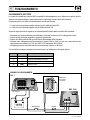
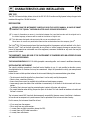
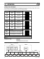
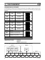
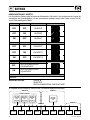
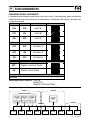
Di seguito viene riportato un possibile schema di una rete di comunicazione CAN:
RDS 1520 KTB4 RCM1620 RDS1540 RCM1620 RDS1520
INTERFACCIA
GSM
TERMINALE
LCD
GRUPPO A GRUPPO B
GRUPPO U
SBC 1950
ADVANCED
PLUS
(Priorità 2)
SBC 1950
ADVANCED
PLUS
(Priorità 3)
SBC 1950
ADVANCED
PLUS
(Priorità 1)
SBC 1100
ADVANCED
PLUS
UNITÀ IN PARALLELO
RETE CAN
CONFIGURAZIONE DELLO STRUMENTO
L'impostazione dello strumento avviene tramite un dip-switch. Per configurare il gruppo, la priorità del caricabat-
teria di cui si vogliono visualizzare le informazioni e la terminazione CAN, riferirsi alla tabella che viene riportata
di seguito:
SWITCH 1
OFF
OFF
ON
SWITCH 2
OFF
ON
OFF
GRUPPO
A
GRUPPO
B
GRUPPO
C
FUNZIONE DESCRIZIONE
SWITCH 6
Non utilizzato
ON
123456
ON
123456
ON
123456
SWITCH 3
OFF
OFF
ON
SWITCH 4
OFF
ON
OFF
PRIORITÀ
1
PRIORITÀ
2
PRIORITÀ
3
FUNZIONE DESCRIZIONE
ON
123456
ON
123456
ON
123456
SWITCH 5
OFF
ON
TERMINATORE CAN DISATTIVATO
TERMINATORE CAN ATTIVATO
FUNZIONE DESCRIZIONE
IMPOSTAZIONE DI FABBRICA:
ON
12345 6
ON
12345 6
GRUPPO
A
PRIORITÀ
1
TERMINATORE CAN DISATTIVATO
RDS1540
FUNZIONAMENTO

9
RDS 1520 - REV003A
IT
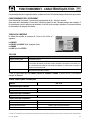
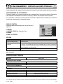
QUICK
®
SI RISERVA IL DIRITTO DI APPORTARE MODIFICHE ALLE CARATTERISTICHE TECNICHE DELL'APPARECCHIO E AL CONTENUTO DI QUESTO MANUALE SENZA ALCUN PREAVVISO.
MODELLO RDS 1520
da 8 a 30 Vdc
100 mA
da -20 a + 70° C
60 mm x 65 mm x 20 mm
60 g
CAN BUS con transceiver differenziale
EN 61326-1 - EN 55011-B - FCC part 15 rules 47
CARATTERISTICHE DI INGRESSO
Tensione di alimentazione
(1)
Assorbimento massimo
CARATTERISTICHE AMBIENTALI
Temperatura operativa
GENERALI
Dimensioni (L x A x P)
Peso
Interfaccia di comunicazione
Classe EMC
(1)
Lo strumento può resettarsi con una tensione di alimentazione inferiore agli 8 Vdc.
CARATTERISTICHE TECNICHE
Per la configurazione di rete del caricabatteria, riferirsi al manuale d'uso del caricabatteria collegato.
FUNZIONAMENTO DELLO STRUMENTO
Prima di alimentare lo strumento assicurarsi che la configurazione del dip-switch sia corretta.
Dopo aver collegato l'alimentazione allo strumento, il display e tutti i led si accendono per due secondi.
Se i collegamenti sono stati effettuati in maniera corretta, il led LINK resterà sempre acceso e lo strumento
visualizzerà le informazioni del caricabatteria.
• Per le segnalazioni dei led
POWER
,
FASE DI CARICA
ed
ERROR
, riferirsi al manuale d'uso del caricabatteria.
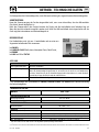
PANNELLO DI CONTROLLO
Il pannello di controllo è composto da 4 led ed una cifra a
7 segmenti:
led
POWER
,
led
FASE DI CARICA
(bulk, absorption, float),
led
ERROR
,
led
LINK
e cifra
STATUS
.
LED LINK
DESCRIZIONE
Collegamento presente.
Collegamento non presente. Se il caricabatteria è spento, questa segnalazione è corretta.
Se il caricabatteria è acceso, provare a spegnere e riaccendere lo strumento, verificare il
collegamento del cavo di trasmissione dati, la configurazione del gruppo, la priorità e la
terminazione CAN.
Configurazione del dip-switch errata.
STATO LED
Sempre acceso (giallo)
Il led lampeggia lentamente
Il led lampeggia velocemente
FUNZIONAMENTO - DATI TECNICI

10
CHARACTERISTICS AND INSTALLATION
RDS 1520 - REV003A
GB
RDS 1520
The RDS 1520 remote display allows status of the SBC ADV PLUS medium and high power battery chargers to be
monitored through the CAN BUS interface.
INSTALLATION
BEFORE USING THE INSTRUMENT CAREFULLY READ THIS USER’S MANUAL. IN CASE OF DOUBT
CONTACT THE “QUICK
®
” SUPPLIER OR AFTER SALES SERVICE DEPARTMENT.
In case of discordance or errors in translation between the translated version and the original text in
the Italian language, reference will be made to the Italian or English text.
This device was designed and constructed for use on recreational crafts.
Other forms of use are not permitted without written authorization from the company Quick
®
.
The Quick
®
RDS 1520 remote control panel has been designed for the purposes and tasks outlined in this User's
Manual. Quick
®
shall not be held responsible for any direct or indirect property damage or personal injury
caused by inappropriate or unintended use of the equipment, erroneous installation or any errors that may be
present in this manual.
THE WARRANTY SHALL BE VOID IF THE INSTRUMENT IS TAMPERED WITH OR ALTERED BY NON
AUTHORISED PERSONNEL.
THE PACKAGE CONTAINS:
RDS 1520 - drilling template - connecting cable - user's manual - conditions of warranty.
INSTALLING THE INSTRUMENT
The typical installation procedure is described herein. Needless to say, it is not possible to describe a proce-
dure applicable for all situations that may be encountered. Adapt this procedure to satisfy your own personal
requirements.
Locate the most suitable position to house the instrument following the recommendations given below:
• The instrument should be installed in a place where it can be easily read by the operator.
• Select a clean, smooth and flat area.
• Access from the rear must be available for installation and maintenance purposes.
• Leave enough space free behind the installation to conveniently fit the back of the instrument and the con-
nectors.
• The back of the instrument must be protected against contact with water and moisture.
• Pay careful attention when drilling the panel or parts of the boat. This hole should not weaken or break/crack
the boat's structure.
The instrument meets EMC standards (electromagnetic compatibility) however correct installation is fundamen-
tal in order not to compromise its performance as well as operation of the instruments found nearby.
For this reason, the instrument should be at least:
• 25 cm away from the compass.
• 50 cm away from any radio receivers.
• 1 m away from any radio transmitters (except for SSB).
• 2 m away from any SSB radio transmitters.
• 2 m away from radar beams.
F
F

11
INSTALLATION
RDS 1520 - REV003A
GB
STATUS
POWER
BULK
ABSORPTION
FLOAT
ERROR
LINK
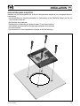
PANEL INSTALLATION
After selecting the area where the instrument is to be installed, perform the steps given below:
• Place the drilling template (supplied) on the surface where the instrument will be installed.
• Mark the center of each hole.
• Drill the hole for the back of the instrument with a 57 mm cutter.
• Remove the template and any burrs present in the hole.
• Put the instrument in place.
• Secure the instrument to the panel with 4 screws (not included in the equipment).

12
RDS 1520 - REV003A
GB
POSITION
1
2
3
4
SIGNAL
+
-
CANH
CANL
Instrument positive power supply
Instrument negative power supply
CAN interface
CAN interface
DESCRIPION
ELECTRIC CONNECTIONS
The instrument meets EMC standards (electromagnetic compatibility) however correct installation is fundamen-
tal in order not to compromise its performance as well as operation of the instruments found nearby. For this
reason, the instrument's cables must be at least:
• 1 m away from cables that carry radio signals (except for SSB radio transmitters).
• 2 m away from cables that carry SSB radio transmitter radio signals.
Follow the rules given below when doing the electrical work for the instrument:
• Turn on power to the instrument only after making and checking that all the electric connections are correct.
• Put in a switch to turn on and shut off the instrument.
• Install a 200 mA fast blow fuse on the instrument's power supply line.
• Use an unscreened cable with a braided pair (cross section 0.25/ 0.35 mm
2
AWG 22/24, impedance 100/150
ohm) for data interface connection (CANH and CANL signals).
• The data cable cannot be more than 100 meters long.
A terminal block is found at the back of the instrument for connection of the various electric signals.
ON
123456
1234
BATTERY
12V / 24V
SWITCH FUSE
RDS 1520
SBC ADV PLUS
FEMALE
CONNECTOR
A 9 PINS DB9
CONNECTION DIAGRAM
FIG. 1
OPERATING

13
RDS 1520 - REV003A
GB
ACTIVATING THE TERMINATORS
Activate the termination at the first and last device connected to the network. To activate the termination, see
fig. 2 and paragraph SETTING UP THE INSTRUMENT.
An example showing network connection is given below:
ON
123456
FIG. 2
DIP-SWITCH
ON
123456
1234
ON
123456
DB9 TERMINATION ACTIVED DB9
RDS 1520
SBC ADV PLUS SBC ADV PLUS
CAN DEVICES
DA 3 A 19
TERMINATION
ACTIVED
DIP-SWITCH
21
20
OPERATING

14
RDS 1520 - REV003A
GB
A possible CAN network is illustrated below:
SETTING UP THE INSTRUMENT
The instrument is set up using a dip-switch. To configure the unit, priority of the battery charger which the infor-
mation is shown for and CAN termination, refer to the table given below:
SWITCH 1
OFF
OFF
ON
SWITCH 2
OFF
ON
OFF
GROUP
A
GROUP
B
GROUP
C
FUNCTION DESCRIPTION
SWITCH 6
Not used
ON
123456
ON
123456
ON
123456
SWITCH 3
OFF
OFF
ON
SWITCH 4
OFF
ON
OFF
PRIORITY
1
PRIORITY
2
PRIORITY
3
FUNCTION DESCRIPTION
ON
123456
ON
123456
ON
123456
SWITCH 5
OFF
ON
CAN TERMINATOR DEACTIVATED
CAN TERMINATOR ACTIVATED
FUNCTION DESCRIPTION
FACTORY SETTING:
ON
12345 6
ON
12345 6
GROUP
A
PRIORITY
1
CAN TERMINATION DEACTIVATED
RDS 1520 KTB4 RCM1620 RDS1540 RCM1620 RDS1520
GSM
INTERFACE
LCD
TERMINAL
GROUP A GROUP B
GROUP U
SBC 1950
ADVANCED
PLUS
(Priority 2)
SBC 1950
ADVANCED
PLUS
(Priority 3)
SBC 1950
ADVANCED
PLUS
(Priority 1)
SBC 1100
ADVANCED
PLUS
UNITS IN PARALLEL
CAN NETWORK
RDS1540
OPERATING

15
RDS 1520 - REV003A
GB
QUICK
®
RESERVES THE RIGHT TO MODIFY THE TECHNICAL CHARACTERISTICS OF THE EQUIPMENT AND THE CONTENTS OF THIS MANUAL WITHOUT PRIOR NOTICE.
MODEL RDS 1520
from 8 to 30 Vdc
100 mA
from -20 to + 70° C
60 mm x 65 mm x 20 mm
60 g
CAN BUS with differential transceiver
EN 61326-1 - EN 55011-B - FCC part 15 rules 47
INPUT CHARACTERISTICS
Supply voltage
(1)
Maximum absorption
AMBIENT CHARACTERISTICS
Operating temperature
GENERAL
Dimensions (W x H x D)
Weight
Communication interface
Classe EMC
(1)
The instrument can reset itself at a voltage less than 8 Vdc.
TECHNICAL DATA
For more information about battery charger configuration, consult the User's manual for the battery charger
used.
INSTRUMENT OPERATION
Before attempting to turn on the instrument, make certain the dip - switch is set to the correct position. After
hooking up the instrument to the power supply, the display screen and all the leds come on for two seconds. If
the connections are correct, led LINK will stay on and the instrument will show information about the battery
charger.
• For a detailed description of the
POWER
,
CHARGE PHASE
and
ERROR
leds, consult the User's manual for
the battery charger.
CONTROL PANEL
The control panel consists of 4 leds and a 7 digit value:
led
POWER
,
led
CHARGE PHASE
(bulk, absorption, float),
led
ERROR
,
led LINK and digit value STATUS.
LED LINK
DESCRIPTION
Link present.
If the battery charger is turned off, the led should be in this state.
If the battery charger is turned on, try switching the instrument off and on, check the data
transmission cable connection, the group configuration, the priority and CAN termination.
Dip-switch in wrong position
LED STATUS
On (yellow)
Led flashes slowly
Led flashes quickly
OPERATING - TECHNICAL DATA

16
CARACTÉRISTIQUES ET INSTALLATION
RDS 1520 - REV003A
FR
RDS 1520
Le tableau déporté RDS 1520 est un instrument qui permet de contrôler l'état des charge de batterie SBC ADV
PLUS medium et high power, par l'intermédiaire de l'interface CAN BUS.
INSTALLATION
AVANT D'UTILISER L'INSTRUMENT, LIRE ATTENTIVEMENT CE LIVRET D'UTILISATION.
EN CAS DE DOUTE, CONTACTER LE REVENDEUR OU LE SERVICE APRES VENTE CLIENTS QUICK
®
.
En cas de discordances ou d’erreurs éventuelles entre la traduction et le texte original en italien, se référer
au texte italien ou anglais.
Ce dispositif a été conçu et réalisé pour être utilisé sur des bateaux de plaisance.
Tout autre emploi est interdit sans autorisation écrite de la société Quick
®
.
Le tableau à distance RDS 1520 Quick
®
a été conçu pour les utilisations décrites dans ce livret d'utilisation. La
société Quick
®
ne peut être tenue responsable des dommages directs ou indirects causés par une utilisation
impropre de l'appareil, par une mauvaise installation ou par de possible erreurs présentes dans ce livret.
L'ENDOMMAGEMENT DE L'INSTRUMENT PAR UN PERSONNEL NON AUTORISE ENTRAINE
L'ANNULATION DE LA GARANTIE.
L'EMBALLAGE CONTIENT LES ÉLÉMENTS SUIVANTS:
RDS 1520 - gabarit de perçage - câble de branche-
ment - conditions de garantie - manuel de l'utilisateur.
INSTALLATION DE L'INSTRUMENT
Ci-dessous nous avons décrit une procédure d'installation typique.
Il est impossible de décrire une procédure qui soit applicable à toutes les situations.
Adapter cette procédure afin de répondre à vos exigences propres.
Trouver la position la plus adaptée pour réaliser les logements qui vont recevoir l'instrument en suivant les critè-
res suivants:
• L'instrument doit être placé de manière à ce qu'il puisse être lu facilement par l'opérateur.
• Choisir un emplacement qui est propre, lisse et plan.
• Il doit y avoir un accès par l'arrière pour faciliter l'installation et l'entretien.
• Il doit y avoir un espace suffisant derrière la position choisie pour placer le dos de l'instrument et les connec-
teurs.
• La partie arrière de l'instrument doit être protégée contre tout contact avec l'eau ou l'humidité.
• Faire particulièrement attention quand vous réalisez les orifices sur les panneaux ou sur certaines parties
de l'embarcation. Ces orifices ne doivent pas fragiliser ou causer la rupture de la structure de l'embarcation.
L'instrument répond aux standards EMC (compatibilité électromagnétique) mais il est nécessaire de procéder
à une installation correcte afin de ne pas compromettre ses propres prestations et celles des instruments qui
sont placés à côté.
Pour cette raison l'instrument doit être éloigné d'au moins:
• 25 cm du compas.
• 50 cm d'un appareil radio récepteur quelconque.
• 1 m d'un appareil radio transmetteur quelconque (sauf SSB).
• 2 m d'un appareil radio transmetteur quelconque SSB.
• 2 m des faisceaux radar.
F
F

17
INSTALLATION
RDS 1520 - REV003A
FR
STATUS
POWER
BULK
ABSORPTION
FLOAT
ERROR
LINK
INSTALLATION SUR PANNEAU
Après avoir choisi l'emplacement de l'instrument, procéder comme reporté ci-dessous:
• Placet le gabarit de perçage (fourni avec l'équipement) sur la surface où sera installé l'instrument.
• Marquer le centre de claque orifice.
• Réaliser découpe pour le dos de l'instrument avec une fraise de diamètre 57 mm.
• Retirer le gabarit et les éventuelles ébarbures présentes sur les orifices.
• Introduire l'instrument dans son logement.
• Fixer l'appareil au panneau au moyen de 4 vis (pas fournies avec l'appareil).

18
RDS 1520 - REV003A
FR
POSITION
1
2
3
4
SIGNAL
+
-
CANH
CANL
Positif alimentation instrument
Négatif alimentation instrument
Interface CAN
Interface CAN
DESCRIPTION
BRANCHEMENT ELECTRIQUE
L'instrument répond aux standards EMC (compatibilité électromagnétique) mais il est nécessaire de procéder à
une installation correcte afin de ne pas compromettre son bon fonctionnement ni celui des instruments qui sont
placés à côté.
Pour cette raison l'instrument doit être éloigné d'au moins:
• 1 m des câbles qui transportent un signal radio (sauf émetteurs BLU).
• 2 m des câbles qui transportent le signal radio d'émetteurs BLU.
Suivre les règles reportées ci-dessous pour la réalisation de l'installation électrique relative à l'instrument:
• N'alimenter l'instrument qu'après avoir effectué et vérifié que tous les branchements électriques sont cor-
rects.
• Introduire un interrupteur pour allumer et éteindre l'appareil.
• Introduire un fusible rapide de 200 mA sur la ligne d'alimentation de l'instrument.
• Utiliser comme connexion de l'interface données (signaux CANH et CANL) un câble non blindé avec un couple
tressé (section 0.25/ 0.35 mm
2
AWG 22/24, impédance 100/150 ohm).
• La longueur maximale totale du câble données doit être inférieure à 100 mètres.
Au dos de l'instrument se trouve un bornier de connexion pour les divers branchements des signaux électriques:
ON
123456
1234
BATTERIE
12V / 24V
INTERRUPTEUR FUSIBLE
RDS 1520
SBC ADV PLUS
CONNECTEUR
BROCHE
À 9 PINS DB9
SCHÉMA DE CONNEXION
FIG. 1
FONCTIONNEMENT

19
RDS 1520 - REV003A
FR
ACTIVATION DES TERMINAUX
Activer la terminaison sur le premier et sur le dernier dispositif relié au réseau.
Pour activer la terminaison sur l'instrument, voir fig. 2, et paragraphe CONFIGURATION DE L'INSTRUMENT.
Nous avons reporté ci-dessous un exemple de branchement du réseau:
ON
123456
FIG. 2
DIP-SWITCH
ON
123456
1234
ON
123456
DB9 TERMINAISON ACTIVÉE DB9
RDS 1520
SBC ADV PLUS SBC ADV PLUS
DISPOSITIFS CAN
DA 3 A 19
TERMINAISON
ACTIVÉE
DIP-SWITCH
21
20
FONCTIONNEMENT

20
RDS 1520 - REV003A
FR
Nous avons reporté ci-dessous le schéma d'un réseau de communication CAN possible:
CONFIGURATION DE L'INSTRUMENT
Le paramétrage de l'instrument se fait au moyen d'un dip-switch. Pour configurer le groupe, la priorité du char-
geur de batteries dont on veut afficher les informations et la terminaison CAN, faire référence au tableau reporté
ci-dessous:
SWITCH 1
OFF
OFF
ON
SWITCH 2
OFF
ON
OFF
GROUPE
A
GROUPE
B
GROUPE
C
FONCTION DESCRIPTION
SWITCH 6
Non utilisé
ON
123456
ON
123456
ON
123456
SWITCH 3
OFF
OFF
ON
SWITCH 4
OFF
ON
OFF
PRIORITÉ
1
PRIORITÉ
2
PRIORITÉ
3
FONCTION DESCRIPTION
ON
123456
ON
123456
ON
123456
SWITCH 5
OFF
ON
TERMINAL CAN DÉSACTIVÉ
TERMINAL CAN ACTIVÉ
FONCTION DESCRIPTION
PARAMÉTRAGE D'USINE :
ON
12345 6
ON
12345 6
GROUPE
A
PRIORITÉ
1
TERMINAL CAN DÉSACTIVÉ
RDS 1520 KTB4 RCM1620 RDS1540 RCM1620 RDS1520
INTERFACE
GSM
TERMINAL
LCD
GROUPE A GROUPE B
GROUPE U
SBC 1950
ADVANCED
PLUS
(Priorité 2)
SBC 1950
ADVANCED
PLUS
(Priorité 3)
SBC 1950
ADVANCED
PLUS
(Priorité 1)
SBC 1100
ADVANCED
PLUS
UNITÉ EN PARALLÉLE
RETE CAN
RDS1540
FONCTIONNEMENT
La pagina sta caricando ...
La pagina sta caricando ...
La pagina sta caricando ...
La pagina sta caricando ...
La pagina sta caricando ...
La pagina sta caricando ...
La pagina sta caricando ...
La pagina sta caricando ...
La pagina sta caricando ...
La pagina sta caricando ...
La pagina sta caricando ...
La pagina sta caricando ...
La pagina sta caricando ...
La pagina sta caricando ...
La pagina sta caricando ...
La pagina sta caricando ...
-
 1
1
-
 2
2
-
 3
3
-
 4
4
-
 5
5
-
 6
6
-
 7
7
-
 8
8
-
 9
9
-
 10
10
-
 11
11
-
 12
12
-
 13
13
-
 14
14
-
 15
15
-
 16
16
-
 17
17
-
 18
18
-
 19
19
-
 20
20
-
 21
21
-
 22
22
-
 23
23
-
 24
24
-
 25
25
-
 26
26
-
 27
27
-
 28
28
-
 29
29
-
 30
30
-
 31
31
-
 32
32
-
 33
33
-
 34
34
-
 35
35
-
 36
36


in altre lingue
- English: Quick RDS 1520 User manual
- français: Quick RDS 1520 Manuel utilisateur
- español: Quick RDS 1520 Manual de usuario
- Deutsch: Quick RDS 1520 Benutzerhandbuch
Documenti correlati
-
Quick RDS 1540 Manuale utente
-
-
-
-
-
-
Quick SBC 1950 ADV PLUS Manuale utente
-
-
-