
PUB. DIM-1164-000
This guide introduces only basic functions. To download the Instruction
Manual, which contains more advanced information, refer to page 7.
4K Camcorder
Quick Guide
Ce guide présente uniquement les fonctions de base. Pour télécharger le
mode d’emploi contenant des informations plus approfondies, consultez
la page 6.
Caméscope 4K
Guide rapide
Esta guía solo muestra las funciones básicas. Para descargar el manual
de instrucciones, que contiene información más avanzada, consulte la
página 5.
Videocámara 4K
Guía breve
English
Français
Español

2
Important Usage Instructions
WARNING – To reduce the risk of electric shock, do not expose this product to dripping or splashing.
To reduce the risk of fire or electric shock, do not expose this apparatus to dripping or splashing, and do not place objects filled with
liquids, such as vases, on the apparatus.
WARNING
TO REDUCE THE RISK OF ELECTRIC SHOCK AND TO REDUCE ANNOYING INTERFERENCE, USE THE RECOMMENDED ACCESSORIES
ONLY.
Water and Moisture - Hazard of electric shock - Do not use this product near water or in rainy/moist situations.
Objects and Liquid Entry - Never push objects of any kind into this product through openings as they may touch dangerous voltage
points or short out parts that could result in a fire or electric shock. Be careful not to spill liquid of any kind onto the product.
COPYRIGHT WARNING:
Unauthorized recording of copyrighted materials may infringe on the rights of
copyright owners and be contrary to copyright laws.
FCC NOTICE
4K Camcorder, XC15 Systems.
This device complies with Part 15 of the FCC Rules. Operation is subject to the following two conditions:
(1) This device may not cause harmful interference, and (2) this device must accept any interference received, including interference
that may cause undesired operation.
Note: This equipment has been tested and found to comply with the limits for class B digital device, pursuant to Part 15 of the FCC
Rules. These limits are designed to provide reasonable protection against harmful interference in a residential installation. This
equipment generates, uses and can radiate radio frequency energy and, if not installed and used in accordance with the
instructions, may cause harmful interference to radio communications. However, there is no guarantee that interference will not
occur in a particular installation. If this equipme
nt does cause h
armful interference to radio or television reception, which can be
determined by turning the equipment off and on, the user is encouraged to try to correct the interference by one or more of the
following measures:
• Reorient or relocate the receiving antenna.
•Increase the separation between the equipment and receiver.
• Connect the equipment into an outlet on a circuit different from that to which the receiver is connected.
•Consult the dealer or an experienced radio/TV technician for help.
Use of shielded cable is required to comply with class B limits in Subpart B of Part 15 of FCC Rules.
Do not make any changes or modifications to the equipment unless otherwise specified in the manual.
If such changes or modifications should be made, you could be required to stop operation of the equipment.
Model ID0080 (including WLAN Module Model RF400, FCC ID: AZD400)
This device complies with Industry Canada license-exempt RSS standard(s). Operation is subject to the following two conditions: (1)
this device may not cause interference, and (2) this device must accept any interference, including interference that may cause
undesired operation of the device.
This tr
ansmitter must no
t be co-located or operated in conjunction with any other antenna or transmitter.
The available scientific evidence does not show that any health problems are associated with using low power wireless devices.
There is no proof, however, that these low power wireless devices are absolutely safe. Low power wireless devices emit low levels
of radio frequency energy (RF) in the microwave range while being used. Whereas high levels of RF can produce health effects (by
heating tissue), exposure of low-level RF that does not produce heating effects causes no known adverse health effects. Many
studies of low-level RF exposures have not found any biological effects. Some studies have suggested that some biological effects
might occur, but such findings have not been confirmed by additional research. This mode
l has been
tested and found to comply
with FCC/IC radiation exposure limits set forth for an uncontrolled equipment and meets the FCC radio frequency (RF) Exposure
Guidelines and RSS-102 of the IC radio frequency (RF) Exposure rules.

3
English
Compliance with FCC requirement 15.407(c) Data transmission is always initiated by software, which is the passed down through
the MAC, through the digital and analog baseband, and finally to the RF chip. Several special packets are initiated by the MAC. These
are the only ways the digital baseband portion will turn on the RF transmitter, which it then turns off at the end of the packet.
Therefore, the transmitter will be on only while one of the aforementioned packets is being transmitted. In other words, this device
automatically discontinues transmission in case of either absence of information to transmit or operational failure.
High-power radars are allocated as primary users (i.e. priority users) of the bands 5250-5350 MHz and 5650-5850 MHz and that
these radars could cause interference and/or damage to LE-LAN devices.
Frequency Tolerance: 25 ppm
Canon U.S.A., Inc.
One Canon Park, Melville, NY 11747, USA
Tel No. 1-800-OK-CANON (1-800-652-2666)
The Mains plug is used as the disconnect device. The Mains plug shall remain readily operable to disc
o
nnect the plug in case of an
accident.
CA-945 identification plate is located on the bottom.
CAUTION:
TO REDUCE THE RISK OF ELECTRIC SHOCK,
DO NOT REMOVE COVER (OR BACK). NO
USER-SERVICEABLE PARTS INSIDE. REFER
SERVICING TO QUALIFIED SERVICE
PERSONNEL.
CAUTION
RISK OF ELECTRIC SHOCK
DO NOT OPEN
The lightning flash with arrowhead symbol, within an equilateral
triangle, is intended to alert the user to the presence of uninsulated
“dangerous voltage” within the product’s enclosure, that may be of
sufficient magnitude to constitute a risk of electric shock to
persons.
The exclamation point, within an equilateral triangle, is intended to
alert the user to the presence of important operating and
maintenance (servicing) instructions in the literature accompanying
the product.

4
Important Safety Instructions
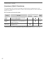
REGIONS OF USE
XC15 is in compliance (as of June 2016) with the radio signal regulations of the regions listed below. For details on other regions where
they can be used, make inquiries with the contacts listed on the back cover of this guide.
Precautions About the Battery Pack
DANGER!
Treat the battery pack with care.
• Keep it away from fire (or it might explode).
• Do not expose the battery pack to temperature higher than 60 °C (140 °F). Do not leave it near a heater or
inside a car in hot weather.
• Do not try to disassemble or modify it.
• Do not drop it or subject it to shocks.
• Do not get it wet.
Important Note about the Recording Media
• Observe the following precautions while the ACCESS indicator is on or flashing in red. Failure to do so may
result in permanent data loss or damage to the recording media.
- Do not disconnect the camcorder’s power source or turn off the camcorder.
- Do not open the recording media slot cover.
- Do not change the camcorder’s operating mode.
CAN ICES-3(B)/NMB-3(B)
REGIONS
Canada, Hong Kong S.A.R., South Korea, Taiwan, USA
Model
ID0080: XC15
In these safety instructions the word “apparatus” refers to the
Canon 4K Camcorder XC15 and all its accessories.
1. Read these instructions.
2. Keep these instructions.
3. Heed all warnings.
4. Follow all instructions.
5. Do not use this apparatus near water.
6. Clean only with dry cloth.
7. Do not install near any heat sources such as radiators, heat
registers, stoves, or other apparatus (including amplifiers)
that produce heat.
8. Do not defeat the safety purpose of the polarized or
grounding-type plug. A polarized plug has two blades with
one wider than the other.
A grounding type plug has two blades and a third grounding
prong. The wide blade or the third prong are provided for your
safety. If the provided plug does not fit into your outlet,
consult an electrician for replacement of the obsolete outlet.
9. Protect the power cord from being walked on or pinched
par
t
icularly at plugs, convenience receptacles, and the point
where they exit from the apparatus.
10.Only use attachments/accessories specified by the
manufacturer.
11.Unplug this apparatus during lightning storms or when
unused for long periods of time.
12.Refer all servicing to qualified service personnel. Servicing is
required when the apparatus has been damaged in any way,
such as power-supply cord or plug is damaged, liquid has
been spilled or objects have fallen into the apparatus, the
apparatus has been exposed to rain or moisture, does not
operate normally, or has been dropped.

5
English
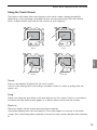
Viewing the Certification Logo
You can open the [ System Setup] > [5] (in mode) or [4] (in mode) >
[Certification Logo Display] screen to view some certification information for this
camcorder.
Trademark Acknowledgements
• SD, SDHC and SDXC Logos are trademarks of SD-3C, LLC.
• Canon is an authorized licensee of the CFast 2.0™ trademark, which may be registered in various jurisdictions.
• Microsoft and Windows are trademarks or registered trademarks of Microsoft Corporation in the United States and/or other
countries.
• Apple, App Store, Mac OS, Final Cut Pro are trademarks of Apple Inc., registered in the U.S. and other countries.
•IOS is a trademark or registered trademark of Cisco in the U.S. and other countries and is used under license.
• Avid and Media Composer are trademarks or registered trademarks of Avid Technology, Inc. or its subsidiaries in the United States
and/or other countries.
•Wi-Fi is a registered trademark of the Wi-Fi Alliance.
• Wi-Fi Certified, WPA, WPA2, and the Wi-Fi Certified logo are trademarks of the Wi-Fi Alliance.
•WPS as used on the camcorder's settings, onscr
een displays
and in this manual signifies Wi-Fi Protected Setup.
• The Wi-Fi Protected Setup Identifier Mark is a mark of the Wi-Fi Alliance.
•JavaScript is a trademark or registered trademark of Oracle Corporation, its affiliates or subsidiaries in the United States and other
countries.
• HDMI, the HDMI logo and High-Definition Multimedia Interface are trademarks or registered trademarks of HDMI Licensing LLC in the
United States and other countries.
•Other names and products not mentioned above may be trademarks or registered trademarks of their respective companies.
• This device incorporates exFAT technology licensed from Microsoft.
• This product is licensed under AT&T patents for the MPEG-4 standard and may be used for encoding MPEG-4 compliant video and/or
decoding MPEG-4 compliant video that was encoded only (1) for a personal and noncommercial purpose or (2) by a video provider
licensed under the AT&T patents to provide MPEG-4 compliant video. No license is granted or implied for any other use for
MPEG-4
standard.

6
Supplied Accessories
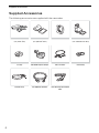
Supplied Accessories
The following accessories are supplied with the camcorder.
CA-945 AC Adapter
(incl. power cord)
LP-E6N Battery Pack
(incl. protective cover)
Lens Hood Viewfinder Unit
(incl. viewfinder unit cover)
Lens Cap MA-400 Microphone Adapter UN-5 Unit Cable Cable Clamp
Shoulder Strap IFC-300PCU/S USB Cable HTC-100/S High Speed HDMI
Cable

7
Table of Contents
English
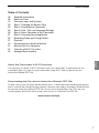
Table of Contents
06 Supplied Accessories
08 Names of Parts
15 Onscreen Icons and Displays
20 Step 1: Charging the Battery Pack
23 Step 2: Preparing the Camcorder
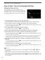
26 Step 3: Date, Time and Language Settings
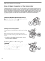
28 Step 4: Basic Operation of the Camcorder
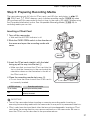
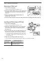
31 Step 5: Preparing Recording Media
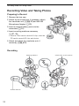
34 Recording Video and Taking Photos
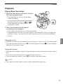
37 Playback
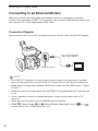
40 Connecting to an External Monitor
41 Saving Clips to a Computer
42 Overview of Wi-Fi Functions
43 Abridged Specifications
About the Camcorder’s Wi-Fi Functions
You can enjoy a variety of Wi-Fi functions with your camcorder. To read about all the
convenient ways you can use your camcorder using Wi-Fi, refer to the full-version
Instruction Manual (PDF file).
Downloading the Full-version Instruction Manual (PDF File)
To learn how to use the more advanced functions, to read important handling precautions
and to consult the troubleshooting section if an error message is displayed, download the
full-version Instruction Manual (PDF file). Access the following Web site. Click on your
country/region and follow the onscreen instructions to download the PDF file.
www.canon.com/icpd

8
Names of Parts
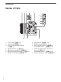
Names of Parts
3512 4
7
8
9
1210 11
6
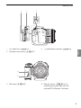
1 Focus ring (; 74)
2Zoom ring (; 73)
3 FOCUS (focus mode) switch
(; 74)
4 AUDIO terminal (; 24)
5 Shoulder strap mount (; 27)
6 MIC (microphone) terminal (; 87)
7 HDMI OUT terminal (; 121)
8USB terminal (; 100)
9DC IN terminal (A 20)
10 DISP. (display) button (; 51)/
Assignable button 1 (; 105)
11 PUSH AF (momentary autofocus)
button (; 79)/
Assignable button 2 (; 105)
12 Exhaust ventilation outlet (; 52)

9
Names of Parts
English
12 3
1 Air intake vent (; 52)
2 Shoulder strap mount (; 27)
3 × (headphone) terminal (; 93)
4
5
4 Tally lamp (; 42) 5 Remote sensor (; 40): For
operating the camcorder with the
optional RC-6 Remote Controller.

10
Names of Parts
1
2
3
4
567
8910
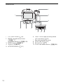
1 LCD touch screen (A 25)
2 MAGN. (magnification) button
(; 77)/
Assignable button 3 (; 105)
3 MENU button (; 30)
4 Joystick (; 30)
5 ACCESS indicator (A 31)
6 CARD OPEN (open recording media
slot cover) lever (A 31)
7 Recording media slot cover
8 CFast card slot (A 31)
9SD card slot (A 31)
10 CFast card release button (; 35)

11
Names of Parts
English
1
3
4
5
6
7
8
9
10
11
2
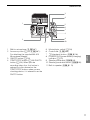
1 Built-in microphone (; 87)
2 Accessory shoe (A 23,; 87):
For attaching the supplied MA-400
Microphone Adapter.
3 ON/OFF button (A 26)
4 START/STOP button (A 34)/PHOTO
button (A 34): When you are
recording video clips, this button is
referred to in this manual as the
START/STOP button; when you are
shooting photos, it is referred to as the
PHOTO button.
5 Movie/photo switch (A 28)
6 Control dial (; 55)
7 ^ (playback) button (; 108)
8 POWER/CHG (power/battery charging)
indicator (A 20)
9 Shooting mode dial (; 55)
10 Shooting mode dial button (; 55)
11 Built-in speaker (; 113)


13
Names of Parts
English
MA-400 Microphone Adapter
1
5
6
7
8
910
2
3
4
1 Audio recording level switches for CH1
(top) and CH2 (bottom) (; 90)
2 INPUT 1 (top)/ INPUT 2 (bottom)
switches (audio source selection)
(; 88)
3 Attachment base
4 Socket for 0.64 cm (1/4") screws
5 – (audio level) dials for CH1 (top)
and CH2 (bottom) (; 90)
6 Microphone lock screw (A 23)
7 Microphone holder: For microphones
with a diameter of ∅19 mm to 20 mm
(0.75" to 0.79").
8 Microphone cable clamp
9 AUDIO terminal (A 23)
10 INPUT 1 (right) and INPUT 2 (left)
terminals (; 88): For
microphones and external audio
sources with an XLR connector.

14
Names of Parts
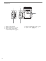
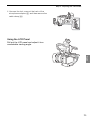
Viewfinder unit
123
1 Viewfinder unit latch (; 22)
2Eye cup
3 Dioptric adjustment lever (; 23)

15
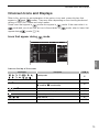
Onscreen Icons and Displays
English
Onscreen Icons and Displays
Refer to this section for an explanation of the various icons and screen displays that
appear in and modes. They may differ depending on the shooting mode and
settings in the FUNC. menu and setup menus.
Some icons that appear in mode also appear in mode. If the camcorder is in
mode and you do not find an icon in these tables for mode, refer to
Icons that
appear during mode
(A 18).
Icons that appear during mode
Icons on the top of the screen
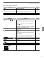
Icon/Display Description ;
n, “, ‚, ’, N, H, û,
, K, L, ÿ, , ,
Shooting mode
55
0:00:00.00, 0:00:00:00 Time code 84
Ü, Ñ Recording operation
Ü: recording, Ñ: record standby
41
, , 0, v Self timer 99
{ Appears when recording a photo in record standby mode. 43
Pre-recording mode 97
, , Image stabilizer 81
[FUNC.] Button to open the FUNC. menu. 30, 137

16
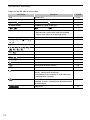
Onscreen Icons and Displays
Icons on the left side of the screen
Icon/Display Description ;
F0.0 Aperture value 55, 58
1/0000, 000.00° Shutter speed, shutter angle 55, 58
y ±0 0/0, y ±0 0/0: AE shift, : exposure locked 65
ISO00000, 00.0dB ISO00000: ISO speed, 00.0dB: gain 55
, : auto ISO limit, : AGC limit 63
@, D 0.0ft Focus mode
• While focusing in manual focus mode, the estimated
distance to the subject will be displayed as well.
74, 76
} Face detection and tracking 79
¼, ½, ¾, ¿, , É, ,
,
White balance 69
– Highlight priority look 71
, , , , , ,
, , ,
Looks 71
O, Peaking 77
ND ND filter 140
¬, , Light metering mode 68
z, { Zebra patterns 82
Digital tele-converter 73
Rolling shutter distortion reduction 140
STBYó, RECó HDMI recording command 145
GPS signal: continuously on - satellite signal acquired;
flashing - satellite signal not acquired.
•Displayed only when an optional GP-E2 GPS Receiver is
connected to the camcorder.
100
Browser Remote: in white – preparations for connections
completed; in yellow – connecting to or disconnecting from
the control device.
131
Exposure bar 58

17
Onscreen Icons and Displays
English
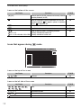
Icons in the center of the screen
Icons on the right side of the screen
Icon/Display Description ;
Remote sensor disabled 40
Onscreen markers 82
Face detection. When a face is detected, a white frame will
appear around the main subject’s face.
79
£ User-selected tracking frame 79
Icon/Display Description ;
è, é, ê, ,
000 min
Remaining battery charge
The icon shows an estimate of the remaining charge. The
remaining recording time is displayed, in minutes, next to
the icon.
• When is displayed, replace the battery pack with a
fully charged one.
• Depending on the conditions of use, the actual battery
charge may not be indicated accurately.
–
{Ð8 Recording a photo. If an SD card error occurs, 9 will
appear instead.
43
0h00m, 8 0h00m Recording media status and available recording time
estimate
• The remaining available space is displayed, in minutes,
next to the icon.
• When the icon appears in red followed by [END], there is
no more available space and recording will stop.
–
Zoom indicator 73
¼, ½, », º,
000Mbps
Frame rate
Bit rate
53
¹ Movie format –
INPUT terminals deactivated 88
Audio peak limiter 90
š, Ÿ, Audio output channel 120
Audio recording level 89, 91

18
Onscreen Icons and Displays
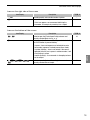
Icons on the bottom of the screen
Icons that appear during mode
Icons on the top of the screen
Icons on the left side of the screen
Icon/Display Description ;
[4K], [HD] Button to open the [4K/HD] submenu and currently selected
recording resolution (4K/HD).
53
When the camcorder’s internal temperature has risen to a
predetermined level, will appear in yellow. If it continues
to rise, will appear in red.
148
` Cooling fan operation 52
^ Magnification (focus assistance function) 77
x1/4, x1/2
x2, x4, x10, x20, x60, x120, x1200
Button to open the [Slow & Fast Motion] submenu.
Currently selected slow motion rate.
Currently selected fast motion rate.
96
Icon/Display Description ;
, , 0, { Self timer 99
Icon/Display Description ;
, , , , , ,
, , ,
Looks 71
ª
, ¬, « Light metering mode 68
, p, Drive mode 44
Orientation detection 102

19
Onscreen Icons and Displays
English
Icons on the right side of the screen
Icons on the bottom of the screen
Icon/Display Description ;
8000 Recording media and available number of photos. –
> Camcorder shake warning
•If this icon appears, we recommend stabilizing the
camcorder, for example, by mounting it on a tripod.
–
Icon/Display Description ;
{L, {S Button to open the [Photo Aspect Ratio] submenu and
currently selected photo size ( or ).
44
g Indicates whether the focus and/or exposure is locked while
the PHOTO button is pressed halfway.
• In green – focus and exposure are locked (during auto
focus mode); exposure is locked (manual focus mode).
• In yellow (flashing) – focus is not locked. If the zoom is
operated while the icon is green in autofocus mode, it will
start flashing in yellow.
• In white (flashing) – the camcorder is attempting to focus
on the subject.
–
, j, , G, , ,
@
Button to open the [Interval Recording] submenu and
currently selected interval length.
98

20
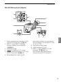
Step 1: Charging the Battery Pack
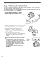
Step 1: Charging the Battery Pack
The camcorder can be powered with a battery pack or directly using the AC adapter. The first time
you use the camcorder, charge the battery pack.
For approximate charging times and recording/playback times with a fully charged battery pack, refer
to
Recording and Playback Times
(; 166).
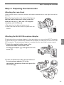
1 Connect the power cord to the AC adapter.
2 Plug the power cord into a power outlet.
3 Connect the AC adapter to the camcorder’s DC IN
terminal.
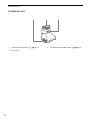
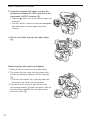
4 Slide the BATT. OPEN switch in the direction of the
arrow and open the battery compartment cover.
5Insert the battery pack all the way into the
compartment as shown in the illustration.
• Push it all the way in until the battery release latch
secures it in place.
6Close the battery compartment cover.
• Push the cover until you hear a click. Do not force the
cover closed if the battery pack is not correctly
inserted.
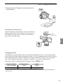
7Charging will start when the camcorder is turned
off.
• If the camcorder was on, the green POWER/CHG
indicator will go out when you turn off the camcorder.
After a moment, the POWER/CHG indicator will
illuminate in red (battery pack charging). The red
POWER/CHG indicator will go out when the battery
pack is fully charged.
• If the indicator flashes, refer to
Troubleshooting
(; 146).
햳
햲
햴
DC IN terminal
햶
햵
POWER/CHG
(battery pack
charging)
indicator
La pagina si sta caricando...
La pagina si sta caricando...
La pagina si sta caricando...
La pagina si sta caricando...
La pagina si sta caricando...
La pagina si sta caricando...
La pagina si sta caricando...
La pagina si sta caricando...
La pagina si sta caricando...
La pagina si sta caricando...
La pagina si sta caricando...
La pagina si sta caricando...
La pagina si sta caricando...
La pagina si sta caricando...
La pagina si sta caricando...
La pagina si sta caricando...
La pagina si sta caricando...
La pagina si sta caricando...
La pagina si sta caricando...
La pagina si sta caricando...
La pagina si sta caricando...
La pagina si sta caricando...
La pagina si sta caricando...
La pagina si sta caricando...
La pagina si sta caricando...
La pagina si sta caricando...
La pagina si sta caricando...
La pagina si sta caricando...
-
 1
1
-
 2
2
-
 3
3
-
 4
4
-
 5
5
-
 6
6
-
 7
7
-
 8
8
-
 9
9
-
 10
10
-
 11
11
-
 12
12
-
 13
13
-
 14
14
-
 15
15
-
 16
16
-
 17
17
-
 18
18
-
 19
19
-
 20
20
-
 21
21
-
 22
22
-
 23
23
-
 24
24
-
 25
25
-
 26
26
-
 27
27
-
 28
28
-
 29
29
-
 30
30
-
 31
31
-
 32
32
-
 33
33
-
 34
34
-
 35
35
-
 36
36
-
 37
37
-
 38
38
-
 39
39
-
 40
40
-
 41
41
-
 42
42
-
 43
43
-
 44
44
-
 45
45
-
 46
46
-
 47
47
-
 48
48


