
7IS-80416 01/09/2021
RETROFIT KIT
KONE
- KRM
- KCEAPM
- KONEXION

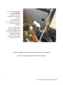
2 INSTALLAZIONE KRM / KRM INSTALLATION
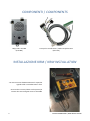
COMPONENTI / COMPONENTS
Helpy 2W-V 12V MK
(5HL-006)
Cavo per kit retrofit Kone / Cable retrofit kit Kone
(5KT-120)
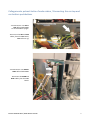
INSTALLAZIONE KRM / KRM INSTALLATION
. Per avere accesso al KRM rimuovere il coperchio
agendo sulle 4 viti evidenziate in foto.
. Unscrew the 4 screws (shown in the picture) to
remove the cover and gain access to the KRM.

INSTALLAZIONE KRM / KRM INSTALLATION 3
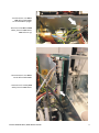
. Disconnettere i cavi XS1 e
XS2 dalla scheda KRM.
La scheda KRM si spegne.
. Disconnect the XS1 and XS2
cables from the KRM board.
KRM will turn off.
. Disconnettere il cavo X12 a
14 vie dalla scheda KRM.
. Disconnect the 14-way X12
cable from the KRM board.

4 INSTALLAZIONE KRM / KRM INSTALLATION
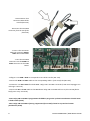
. Collegare il cavo X12 al
corrispondente cavo del kit
retrofit (5KT-120).
. Collegare l’altra estremità
del cavo del kit retrofit al
connettore X12 della scheda
KRM.
. Connect the X12 cable to the
corresponding cable of the
retrofit kit (5KT-120).
. Connect the other end of the
retrofit kit cable to the KRM
board (X12 connector).
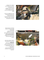
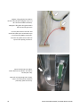
. Disconnettere il cavo RJ11
della linea telefonica dalla
scheda KRM.
. In alcuni casi la linea
telefonica è connessa
direttamente al cavo flessibile
(fili n° 15 e 16, spesso di
colore arancione e bianco).
. Collegare la linea telefonica
al connettore RJ11 del kit
retrofit.
. Disconnect theRJ11 cable of
the telephone line from the
KRM board.
. Sometimes the telephone
line is connected directly to
the trailing cable (wires n° 15
and 16, often orange and
white colors).
. Connect the telephone line
to the RJ11 connector of the
retrofit kit.

INSTALLAZIONE KRM / KRM INSTALLATION 5
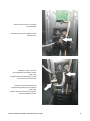
. Connettere la morsettiera
del kit retrofit
all’Helpy 2W-V 12V MK.
. Connect the terminal blocks
of the retrofit kit to the
Helpy 2W-V 12V MK.
. Helpy 2W-V 12V MK può
essere installato sul tetto di
cabina.
. Prima di fissare il
combinatore verificare che il
foro del microfono sia in
corrispondenza di un foro del
tetto e che la qualità audio sia
buona.
. È in ogni caso possibile
fissare il combinatore con
l’altoparlante rivolto verso
l’alto.
. Helpy 2W-V 12V MK can be
installed on the top of the car.
. Please make sure the
microphone is placed in
correspondence with a car
hole and the audio quality is
good.
. In any case Helpy 2W-V 12V
MK can be installed facing
upwards.

6 INSTALLAZIONE KRM / KRM INSTALLATION
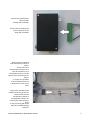
. Connettere i cavi XS1 e XS2
alla scheda KRM.
. Helpy 2W-V 12V MK si
accende (il LED rosso
lampeggia una volta ogni 3
secondi).
. Se il KRM inizia una
procedura di allarme,
disconnettere i cavi XS1 e XS2
per alcuni secondi poi
ricollegarli.
. Connect the XS1 and XS2
cables to the KRM board.
. Helpy 2W-V 12V MK will turn
on (the red LED flashes briefly
once every 3 seconds).
. If KRM starts an alarm,
disconnect the XS1 and XS2
cables for few seconds.
. Nota: per la programmazione minima consultare la tabella in ultima pagina.
. Note: for basic programming see the table in the last page.

INSTALLAZIONE KRM / KRM INSTALLATION 7
Collegamento pulsanti tetto e fondo cabina / Connecting the car-top and
car-bottom pushbuttons
. Disconnettere i cavi XS1 e
XS2 dalla scheda KRM.
La scheda KRM si spegne.
. Disconnect the XS1 and XS2
cables from the KRM board.
KRM will turn off.
. Disconnettere i cavi XC9B e
XC9C dalla scheda KRM.
. Disconnect the XC9B and
XC9C cables from the KRM
board.

8 INSTALLAZIONE KRM / KRM INSTALLATION
. Disconnettere i due
connettori SPOX dal kit
retrofit (5KT-120).
. Disconnect the two SPOX
connector from the retrofit kit
(5KT-120).
. Inserire i due connettori
SPOX nei connettori XC9B e
XC9C della scheda KRM.
. Insert the two SPOX
connectors into the XC9B and
XC9C connectors on the KRM
board.
. Collegare i cavi XC9B e XC9C ai corrispondenti cavi del kit retrofit (5KT-120).
. Connect the XC9B and XC9C cables to the corresponding cables of the retrofit kit (5KT-120).
. Connettere i cavi XS1 e XS2 alla scheda KRM. Helpy 2W-V 12V MK si accende (il LED rosso lampeggia una
volta ogni 3 secondi).
. Connect the XS1 and XS2 cables to the KRM board. Helpy 2W-V 12V MK will turn on (the red LED flashes
briefly once every 3 seconds).
. Nota: Helpy 2W-V 12V MK è programmato di fabbrica per gestire i pulsanti normalmente chiusi di tetto
e fondo cabina (4110).
. Note: Helpy 2W-V 12V MK is factory programmed for normally closed car-top and car-bottom
pushbuttons (4110).

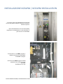
INSTALLAZIONE KCEAPM / KCEPAM INSTALLATION 9
INSTALLAZIONE KCEAPM / KCEAPM INSTALLATION
. Per avere accesso al KCEAPM aprire il pannello
di controllo (MAP) integrato nella porta di piano o
montato a parete.
. Open the Maintenance Access Panel (MAP),
integrated in a landing door or wall-mounted, to
gain access to the KCEAPM.
. Disconnettere i cavi XM31 (segnali) e
X1 (linea telefonica) dal KCEAPM.
Il KCEAPM si spegne.
. Disconnect the XM31 (signals) and X1
(telephone line) cables from the
KCEAPM.
KCEAPM will turn off.

10 INSTALLAZIONE KCEAPM / KCEPAM INSTALLATION
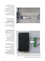
. Tagliare il filo giallo del cavo del kit
retrofit 5KT-120 (filo collegato al pin n° 8
del connettore Molex maschio).
. Collegare il filo giallo all’ingresso libero
del morsetto di giunzione
. Cut the yellow wire of the 5KT-120
retrofit kit cable (wire connected to pin
n° 8 of the male Molex connector).
. Connect the yellow wire to the free
input of the splicing connector.
. Aprire la bottoniera di cabina.
. Calare dal tetto di cabina il cavo del kit
retrofit (5KT-120).
. Open the Car Operating Panel (COP).
. Lower the cable of the retrofit kit
(5KT-120) from the car top.

INSTALLAZIONE KCEAPM / KCEPAM INSTALLATION 11
. Disconnettere il cavo a 14 vie dal
connettore J2.
. Disconnect the 14-way cable from the
J2 connector.
. Collegare il cavo a 14 vie al
corrispondente cavo del kit retrofit
(5KT-120).
. Collegare l’altra estremità del cavo del
kit retrofit al connettore J2.
. Connect the 14-way cable to the
corresponding cable of the retrofit kit
(5KT-120).
. Connect the other end of the retrofit kit
cable to the J2 connector.

12 INSTALLAZIONE KCEAPM / KCEPAM INSTALLATION
. Helpy 2W-V 12V MK si
installa sul tetto di cabina.
. Prima di fissare il
combinatore verificare che il
foro del microfono sia in
corrispondenza di un foro del
tetto e che la qualità audio sia
buona.
. È in ogni caso possibile
fissare il combinatore con
l’altoparlante rivolto verso
l’alto.
.Install Helpy 2W-V 12V MK
on the top of the car.
. Please make sure the
microphone is placed in
correspondence with a car
hole and the audio quality is
good.
. In any case Helpy 2W-V 12V
MK can be installed facing
upwards.
. Prevedere una linea
telefonica (es. interfaccia
GSM500) sul tetto di cabina.
. Collegare la linea telefonica
al connettore RJ11 del kit
retrofit.
.Connettere la morsettiera
del kit retrofit
all’Helpy 2W-V 12V MK.
. Helpy 2W-V 12V MK si
accende (il LED rosso
lampeggia una volta ogni 3
secondi).
. Place a telephone line (e.g.
GSM500 gateway) on the
cabin roof.
. Connect the telephone line
to the RJ11 connector of the
retrofit kit.
. Connect the terminal blocks
of the retrofit kit to the
Helpy 2W-V 12V MK.
. Helpy 2W-V 12V MK will turn
on (the red LED flashes briefly
once every 3 seconds).
. Nota: per la programmazione minima consultare la tabella in ultima
pagina / Note: for basic programming see the table in the last page.

INSTALLAZIONE KONEXION / KONEXION INSTALLATION 13
INSTALLAZIONE KONEXION / KONEXION INSTALLATION
Collegamento linea telefonica / Connecting the telephone line
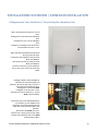
. Aprire la Base Unit installata in cima al
vano.
. Scollegare la linea telefonica dalla Base
Unit.
. Scollegare il cavo a 4 vie dalla Base
Unit.
. Collegare i 2 fili della linea telefonica a
2 fili qualsiasi del cavo a 4 vie.
. Open the Base Unit Module installed at
the top of the lift shaft.
. Disconnect the telephone line from the
Base Unit Module.
. Disconnect the 4-way cable from the
Base Unit Module.
. Connect the 2 wires of the telephone
line to any of the 2 wires in the 4-way
cable.
. Scollegare dalla scheda LCEKNX car
interface (al centro del quadro di
manovra, all’interno del vano) il cavo a 4
vie proveniente dalla Base Unit.
. Scollegare il connettore XC20.
. Collegare i 2 fili del cavo a 4 vie,
utilizzati per la linea telefonica, al cavo
XC20 (cavo flessibile).
. Disconnect from the LCEKNX KoneXion
car interface (in the middle of the
controller, in the lift shaft) the 4-way
cable that comes from the Base Unit
Module .
. Disconnect the XC20 connector.
. Connect the 2 wires of the 4-way cable
used for the telephone line to the XC20
cable (trailing cable).

14 INSTALLAZIONE KONEXION / KONEXION INSTALLATION
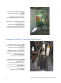
. Aprire la Car Unit installata sul tetto di
cabina.
. Scollegare i 2 fili blu e marrone dalla
Car Unit.
. Collegare i 2 fili blu e marrone ai
morsetti LTI dell’Helpy 2W-V 12V MK.
. Open the Car Unit in Metal Box installed
on the top of the car.
. Disconnect the brown and blue wires
from the Car Unit.
. Connect the brown and blue wires to
the LTI terminals of Helpy 2W-V 12V MK.
Collegamento pulsante / Connecting the pushbutton
. Scollegare il connettore bianco XB18
(cavo 10 vie) dal box installato sul tetto
di cabina.
. Tagliare il filo contrassegnato con il
numero 5.
. Collegare i 2 spezzoni del filo 5 ad una
estremità della bobina di un relè 12 V.
. Collegare l’altra estremità della bobina
alla terra dell’impianto.
. Ricollegare il connettore XB18.
. Disconnect the white connector XB18
(10-way cable) from the box installed on
the top of the car.
. Cut the wire marked with number 5.
. Connect both ends of wire 5 to a side of
a 12 V relay coil.
. Connect the other side of the relay coil
to earth/ground.
. Reconnect the connector XB18.

INSTALLAZIONE KONEXION / KONEXION INSTALLATION 15
. Collegare i contatti (normalmente
aperti) del relè ai morsetti AL1 e —
dell’Helpy 2W-V 12V MK.
. Posizionare il diodo tra i morsetti +12 e
C.
. Connect the normally open contacts of
the relay to AL1 and
—
terminals of
Helpy 2W-V 12V MK.
. Connect the diode between +12 and C
terminals.
. Nota: per la programmazione minima consultare la tabella in ultima pagina.
. Note: for basic programming see the table in the last page.

16 PROGRAMMAZIONE BASE / BASIC PROGRAMMING
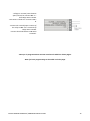
PROGRAMMAZIONE BASE / BASIC PROGRAMMING
Accesso alla programmazione
Access to programming
*0#
1° numero di telefono per richiesta soccorso
1st telephone number for emergency call
210112<numero di telefono/telephone number>#
2° numero di telefono per richiesta soccorso
2nd telephone number for emergency call
210212<numero di telefono/telephone number>#
3° numero di telefono per richiesta soccorso
3rd telephone number for emergency call
210312<numero di telefono/telephone number>#
numero di telefono per chiamata periodica di test (CLI)
telephone number for periodic test call (CLI mode)
210434<numero di telefono/telephone number>#
Registrazione messaggio di identificazione
Record identification message
7101<registrare/record><riagganciare/hang up>
Ascolto messaggio di identificazione
Listen to identification message
7201<ascoltare/listen>
Ritardo pulsante richiesta soccorso
Emergency call button delay
42X (X=3-9 secondi/seconds)
Ingresso di allarme AL1 normalmente chiuso/aperto
Emergency input AL1 normally closed/open
4100 normalmente chiuso/normally closed
4110 normalmente aperto/normally open
Uscita dalla programmazione
Exiting the programming
*0#
-
 1
1
-
 2
2
-
 3
3
-
 4
4
-
 5
5
-
 6
6
-
 7
7
-
 8
8
-
 9
9
-
 10
10
-
 11
11
-
 12
12
-
 13
13
-
 14
14
-
 15
15
-
 16
16


in altre lingue
- English: Esse-ti Retrofit Kit User manual
Documenti correlati
-
Esse-ti 2W Speaker Unit Manuale utente
-
-
-
-
-
-
-