
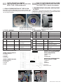
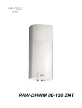
1. VISUAL PRESENTATION OF TYPE 2 FAN
Fan itself is mainly fabricated out of metal (impeller and
mounting ange). It has a distinguished blue rotor cover that
can be easily identied:
Fan type 2 BL-F160C-EC-00 Box description
Ventilatore tipo 2 BL-F160C-EC-00 Descrizione delle scatole
2. TYPE 2 WIRING
Line Signal Colour Assignment/Function
1 L Brown Mains 50/60 Hz, phase
N Blue Mains 50/60 Hz, neutral
PE Green & Yellow Protective Earth
Line Signal Colour Assignment/Function
2+10VDC Red Voltage output+10VDC
max. 1mA
0-10VDC/PWM Yellow Control input
Tach output White Tach output: 2 puls per
revolution
GND Blue GND
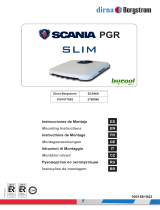
POWER BOX
POWER BOX
Disconnect the fan wires ONLY:
UPPER CONNECTION BOX
(POWER SUPPLY):
1) YE-GN
2) BLUE
3) BROWN
LOWER CONNECTION BOX
(PWM CONTROL):
1) YELLOW
2) BLUE
3) RED
1. PRESENTAZIONE VISIVA DEL VENTILATORE
DI TIPO 2
Il ventilatore è principalmente fabbricato in metallo (girante
e angia di montaggio) e presenta un coperchio del rotore
blu che può essere facilmente identicato:
2. CABLAGGIO TIPO 2
Linea
Segnale
Colore Assegnazione/Funzione
1 L Marrone Rete 50/60 Hz, fase
NBlu Rete 50/60 Hz, neutro
PE Verde & Giallo Protezione terra
Linea
Segnale
Colore Assegnazione/Funzione
2 +10VDC Rosso Uscita tensione+10VDC
max. 1mA
0-10VDC/PWM Giallo Controllo ingresso
Tach output Bianco Tach output: 2 impulsi
per giro
GND Blu GND
Scollegare SOLO i cavi del ventilatore:
SCA
TOLA DI CONNESSIONE SUPE-
RIORE (ALIMENTAZIONE):
1) GIALLO-GN
2) BLU
3) MARRONE
SC
ATOLA DI CONNESSIONE INFE-
RIORE (CONTROLLO PWM):
1) GIALLO
2) BLU
3) ROSSO
FOGLIO SOSTITUZIONE VENTILATORE
TIPO 2 (A BORDO MACCHINA) CON VEN-
TILATORE TIPO 1 (PARTE DI RICAMBIO).
TYPE 2 FAN REPLACEMENT
INSTRUCTION (ON BOARD THE MACHINE)
WITH TYPE 1 FAN (SPARE PART).
VENTILATORE FAN
VENTOLA DEL VENTILATORE
IT
EN
POWER BOX
PWM BOX
POWER BOX
2
3
1
PWM BOX
1
3
2
Doc-0217979 - 01/23 - Ed.0

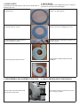
3. BASIC PARTS
All metal parts are fabricated on site and are introduced into
assembly process:
Interior fan bracket – round metal ring with
integrated nuts
Staa ventola interna - anello rotondo in
metallo con dadi integrati
Exterior fan bracket – round metal ring with
mounting holes for screws
Staa ventola esterna - anello metallico
rotondo con fori di montaggio per le viti
A4 and A6 washers, plastic spacers,
M4x16 and M6x10 screws
Rondelle A4 e A6, distanziali in plastica, viti
M4x16 e M6x10
Left and right part of the fan scroll Parte sinistra e destra della coclea del
ventilatore
4. DISASSEMBLY AND ASSEMBLY PROCESS
Remove the connection boxes and
disconnect the fan wires
POWER BOX
PWM BOX
Rimuovere le scatole di connessione e scolle-
gare i cablaggi ventilatore
3. PARTI BASE
Tutte le parti metalliche sono fabbricate in loco e vengono
introdotte nel processo di assemblaggio:
4. FASI DI SMONTAGGIO E MONTAGGIO

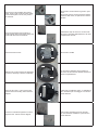
Remove the screws holding the scroll in
place. There is also a pair of screws which
hold the back plate to scroll, they need to
be removed.
Rimuovere le viti che ssano il guscio in posi-
zione.
Rimuovere anche le viti che ssano la piastra
posteriore alla coclea, le quali devono essere
rimosse.
There are clips that hold two halves of
scroll together. Disconnect them gently and
halves will disconnect themselves.
Individuare le clip che uniscono le due metà
del guscio, sganciarle delicatamente e le metà
si separeranno da sole.
Remove the M6 screws. Rimuovere le viti M6.
Slide the fan out and remove the remaining
screws for assembly to detach completely.
Far scorrere il ventilatore verso l’esterno e
rimuovere le viti rimanenti anché l’assieme si
stacchi completamente.
Place the fan Type 1 in and use the atta-
ched screws for mounting. Holes must be
alligned.
Posizionare il ventilatore di tipo 1 e utilizzare le
viti in dotazione per il montaggio. I fori devono
essere allineati
Push the scroll halves together to make a
signle fan unit. Pieces must be aligned.
Unisci le due metà del guscio per formare
un unico assieme ventilatore. I pezzi devono
essere allineati.

5. Cablaggio tipo 1
Linea No. Segnale Colore Funzione/assegnazione
L 1 marrone Alimentazione 230 Vac, 50/60
Hz, vedere la targhetta per l'in-
tervallo di tensione
N 2 blu Conduttore neutro
Pwm 3 giallo Ingresso di controllo PWM,
isolato elettricamente
GND 4bianco GND - Connessione per l'inter-
faccia di controllo
Collegare i li nel seguente ordine:
SCATOLA DI CONNESSIONE SUPERIORE (ALIMENTAZIONE):
1) BLU a BLU
2) MARRONE a ROSSO
Non c’è nessun lo GIALLO/VERDE a causa della costruzione
della ventilatore in plastica
SCATOLA DI CONNESSIONE INFERIORE (CONTROLLO PWM):
3) GIALLO A MARRONE
4) BIANCO A BLU
6. Impo
stazione del parametro PWM corretto, riferito al tipo 1:
Con una pressione prolungata sul campo "modalità assistenza"
(icona della chiave inglese) sul display, accedere alla diagnostica di
assistenza.
Apparirà il menu di servizio con la nota ''codice''. Per entrare nel
menu è necessario inserire il codice.
Campi FN1, FN2, FN3, FN4, FN5 in FN6, presenta i numeri
1,2,3,4,5,6.
Inserire il codice per il menu di servizio 1166.
Trova il parametro 21 e impostalo su 60 (ovvero 60%).
Uscire dal menu di servizio.
VENTILATORE FAN
VENTOLA DEL VENTILATORE
2
1
POWER BOX
PWM BOX
1
2
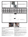
Use the same screws to mount back the
scroll onto evaporator.
Connect the wires afterwards.
Utilizzare le stesse viti per rimontare la parte
posteriore del guscio sull’evaporatore.
Collegare i cablaggi come indicato di seguito.
5. Type 1 wiring
Line No. Signal Colour Function/assignment
L 1 brown Power supply 230
Vac,50/60Hz, see type
plate for voltage range
N 2 blue Neutral conductor
Pwm 3 yellow PWM control input,
electrically isolated
GND 4 white GND - Connection for
control interface
Connect the wires in the following order:
UPPER CONNECTION (POWER BOX):
1) BLUE to BLUE
2) BROWN to RED
There is no YELLO
W/GREEN wire because of plastic fan co
n-
struction.
LOWER CONNECTION (PWM BOX):
1) YELLOW to BROWN
2) WHITE to BLUE
6. Setting the proper PWM parameter, reered to type 1:
With long press on eld ‘’service mode’’ (wrench icon) on the di-
splay, enter into service diagnostic.
The service menu with note ‘‘code’’ will appear. To enter the menu
the code entry is required.
Fields FN1, FN2, FN3, FN4, FN5 in FN6, presents the numbers
1,2,3,4,5,6.
Enter the code for service menu 1166.
Find the parameter 21 and set it to 60 (meaning 60%).
Exit the service menu.
POWER BOX
POWER BOX
-
 1
1
-
 2
2
-
 3
3
-
 4
4


in altre lingue
- English: Riello NexAqua 80 Plus User manual
Altri documenti
-
Carel mchiller compact Manuale utente
-
Panasonic PAWDHWM300AE Istruzioni per l'uso
-
-
Frico PAEC2500 Series Cold Air Curtain Manuale utente
-
Tyan S2932G2NR Manuale utente
-
 Aquarea PAW-DHWM 80-120 ZNT Istruzioni per l'uso
-
Baxi Power HT 1.1200 Installation, Operation and Maintenance Manual
-
-
 dirna Bergstrom 1001877663 Mounting instructions

