La pagina si sta caricando...
La pagina si sta caricando...

Indice
1. Introduzione . . 1
2. Interfaccia utente ...1
2.1Display ....1
2.2 Informazioni sullo stato della macchina . 1
2.3Tastiera ....2
2.4 Impostazione parametri . . 2
2.5 Riassunto delle funzioni dei tasti . 7
3. I parametri ....6
3.1 Descrizione dei parametri . . 11
- Predisposizioni delle sonde (parametri “/”) 11
- Predisposizione del regolatore (parametri “r”) 12
- Attività del compressore (parametri “c”) 14
- Attività delle ventole (parametri “F”) . 16
- Sbrinamento (parametri “d”) . . 18
- Antigelo (parametri “A”) . . 20
- Allarmi (parametri “P”) . . 22
- Parametri generali (“H”) . . 24
4. Allarmi e segnalazioni . . 26
4.1 Tabella riassuntiva degli allarmi. . 26
4.2Allarmi ....26
4.3 Segnalazioni ....28
5. Accessori ....29
5.1 Telecomando a raggi infrarossi . . 29
5.2 MCHSMLSER0: convertitore seriale per µchiller
compact ....30
5.3 MCHSML4200: modulo convertitore per sonda
di pressione 4÷20 mA...32
5.4 Terminale remoto ...33
5.5 Scheda gestione ON/OFF ventilatori . 33
5.6 Schede gestione velocità dei ventilatori . 34
5.7 Scheda di conversione PWM 0÷10V (o 4÷20mA)
per ventilatori ...34
5.8 Calcolo della velocità min. e max. dei ventilatori 35
5.9 Modulo espansione per sonda di
compensazione (cod. MCHSMLEXP0) . 36
6. Le applicazioni ...37
6.1 Unità ARIA/ARIA, 1 compressore . 37
6.2 Pompa di calore ARIA/ARIA, 1 compressore 37
6.3 Chiller ARIA/ACQUA, 1 compressore . 38
6.4 Pompa di calore ARIA/ACQUA, 1 compressore 38
6.5 Chiller ACQUA/ACQUA, 1 compressore . 39
6.6 Pompa di calore ACQUA/ACQUA a reversibilità
del gas, 1 compressore . . 39
6.7 Pompa di calore ACQUA/ACQUA a reversibilità
dell’acqua, 1 compressore . . 39
6.8 Motocondensante ad aria con e senza inversione
di ciclo ....40
6.9 Motocondensante ad acqua con e senza inversione
di ciclo ....40
7. Schema di collegamento . 41
7.1 Note per l’installazione . . 42
8. Dimensioni ....43
9. Codici ....44
10. Caratteristiche tecniche del µchiller compact 45
11. Aggiornamenti software . . 49
11.1 Note per la versione 1.2 . . 49
11.2Note per la versione 1.3 . . 49
11.3Note per la versione 1.4 . . 49
11.4 Note per la versione 2.0 . . 50
Index
1. Introduction....1
2. Used interface ...1
2.1Display ....1
2.2Status of the unit ...1
2.3Keypad ....2
2.4 Parameters setting ...2
2.5 Functions of the button . . 7
3. Parameters ....6
3.1 Parameter description...11
- Probes (parameters “/”) . . 11
- Regulator (parameters “r”) . . 12
- Compressor (parameters “c”) . . 14
- Fans (parameters “F”) . . 16
- Defrosting (parameters “d”) . . 18
- Antifreeze (parameters “A”) . . 20
- Alarms (parameters “P”) . . 22
- General parameters (“H”) . . 24
4. Alarms and signalling . . 26
4.1Alarm table ....26
4.2Alarms ....26
4.3 Signalling ....28
5. Accessories....29
5.1 Infrared remote control unit . . 29
5.2 MCHSMLSER0: serial converter for µchiller
compact ....30
5.3 MCHSML4200: converter module for 4÷20mA
pressure probe ...32
5.4 Remote terminal ...33
5.5 Card for ON/OFF fan control . . 33
5.6 Card for the fan speed control . . 34
5.7 Card for PWM 0÷10V (o 4÷20mA) conversion 34
5.8 How to find min. and max. speed of the fans 35
5.9 Expansion module for compensation probe
(code MCHSMLEXP0) . . 36
6. Applications ...37
6.1 AIR/AIR unit, single-compressor . 37
6.2 AIR/AIR heat pump, single-compressor . 37
6.3 AIR/WATER chiller, single-compressor . 38
6.4 AIR/WATER heat pump, single-compressor 38
6.5 WATER/WATER chiller, single-compressor 39
6.6 WATER/WATER heat pump, single-compressor
with gas reversibility ...39
6.7 WATER/WATER heat pump, single-compressor
with water reversibility...39
6.8 Air motorcondensing unit with or without cycle
inversion ....40
6.8 Water motorcondensing unit with or without cycle
inversion ....40
7. Wiring connection ...41
7.1 How to install the controller . . 42
8. Dimensions ....43
9. Codes ....44
10. µchiller compact technical specifications 45
11. Software updating ...49
11.1 Note for the release 1.2 . . 49
11.2 Note for the release 1.3 . . 49
11.3 Note for the release 1.4 . . 49
11.4Notes for version 2.0 ...50
La pagina si sta caricando...

1. Introduzione
µchiller compact è un controllo elettronico compatto
CAREL, delle dimensioni di un normale termostato, per la
completa gestione di chiller e pompe di calore mono com-
pressore; offre la possibilità di gestire unità aria-aria, aria-
acqua, acqua-acqua e motocondensanti.
Funzioni principali:
•Controllo sulla temperatura dell’acqua ingresso
evaporatore (aria di ripresa)
•Gestione dello sbrinamento a tempo e/o in temperatura
•Controllo della velocità dei ventilatori
•Completa gestione degli allarmi
• Collegabile a linea seriale per supervisione/teleassistenza
•Un terminale esterno collegabile
Dispositivi controllati:
• Compressore
•Ventilatori di condensazione
•Valvola di inversione ciclo
•Pompa di circolazione acqua o ventilatore di mandata
(aria-aria)
•Resistenze antigelo
•Dispositivo di segnalazione di allarme
Programmazione:
Carel offre la possibilità di configurare tutti i parametri
della macchina non solo tramite la tastiera posta sul fron-
tale ma anche da:
• una chiave hardware,
• un telecomando ad infrarosso (opzionale)
• linea seriale.
2. Interfaccia utente
2.1 Display
Il display è composto da 3 cifre con la visualizzazione
automatica del punto decimale tra -19.9 e +19.9 °C; all’e-
sterno di tale campo di misura il valore viene automatica-
mente visualizzato senza decimale (sebbene al suo inter-
no la macchina funzioni sempre considerando la parte
decimale). In funzionamento normale il valore visualizzato
corrisponde alla temperatura letta dalla sonda B1, ovvero
la temperatura acqua ingresso evaporatore (nei refrigera-
tori d’acqua) oppure la temperatura aria-ambiente nelle
unità ad espansione diretta.
2.2 Informazioni sullo stato della macchina
Le informazioni sullo stato della macchina vengono visua-
lizzate mediante 4 LED sul display.
Significato dei LED a display
1. Introduction
Compact µchiller is a versatile electronic controller as
compact as a standard thermostat, specifically designed
for the control of chillers and single-compressor heat
pumps. It controls air-to-air, air-to-water, water-to-water
and condensing units.
Main functions:
•Control of water temperature at evaporator inlet (inlet air)
•Time-based and/or temperature-based defrosting cycles
• Control of fan speed
• Full alarm management
•Can be linked up to serial line for supervisory
telemaintenance control
•Can be linked up to an external terminal unit
Controlled devices:
• Compressor
•Condensation fans
•Reverse cycle valve
•Water pump or supply fan (air-to-air)
• Antifreeze heaters
•Alarm signalling device
Programming:
All parameters can be easily configured not only by key-
pad but also through:
• hardware key
• infrared remote control (optional)
• serial line
2. User interface
2.1 Display
The display consists of 3 digits, with the automatic display
of the decimal point between -19.9 and + 19.9°C; outside
this measurement range, the value is automatically
displayed without decimal (although in its inside the
machine is always operating by taking into account the
decimal part). During the normal operation, the displayed
value corresponds to the temperature being read by the
probe B1, that is the evaporator water in-let temperature
(in water refrigerators) or the ambient-air temperature in
the direct expansion units.
2.2 Status of the unit
The User is informed of the status of the unit by means of
four LEDs on the display.
Meaning of LEDs in single-compressor units
1
comp
x 100
clear
PRG
mute
SEL
LED Acceso lampeggiante / Flashing Acceso fisso / Steady
Comp / Comp. Compres. richiesto/Request for compres. Compres. attivato/Compressor actuated
Estate / Cooling -Modalità refrigeratore/cooling (Hd=0)
Inverno / Heating -Modalità pompa calore/heating (Hd=0)
x100 - Valore visualizzato x100/Visualized value x100

2.3 Tastiera
La tastiera permette l’impostazione dei valori di
funzionamento della macchina.
Di seguito viene indicato il significato di ciascun
tasto.
2.4 Impostazione parametri
Modalità di accesso al Set Point ed ai parametri
principali di controllo del funzionamento della
macchina (parametri DIRECT).
La pressione di SEL per più di 5 secondi cosente di
visualizzare il set point estivo e invernale e i parametri
principali di controllo della macchina denominati
parametri DIRECT; il display visualizzerà il codice del
primo parametro DIRECT disponibile, ovvero il set
point estivo. La pressione di e consente di scorrere
tutti i parametri DIRECT. La nuova pressione di SEL per-
mette di visualizzare il valore del parametro DIRECT pre-
scelto, consentendone la eventuale modifica tramite i tasti
e (cap.3). La pressione di PRG memorizza i parametri
variati e fa uscire dalla procedura, mentre il tasto SEL
consente di ritornare al menù di scelta dei parametri DIRECT.
In fase di impostazione dei parametri, se non si esegue
alcuna operazione sulla tastiera per qualche secondo, il
display lampeggia. Se dopo 60 secondi dall'attivazione
della procedura nessun tasto è stato premuto il controllo
torna alla modalità di funzionamento normale senza la
memorizzazione dei parametri eventualmente modificati.
Modalità di accesso ai param. utilizzatore (param. USER).
La pressione di PRG per più di 5 secondi
consente di accedere al menù di predisposizione
dei param. USER, ovvero dei parametri di “lavoro”
della macchina.Tale livello è protetto da un codice
(password) per evitare l’accesso dei dati alle
persone non autorizzate. Impostazione password:
Appare "0"; utilizzare i tasti e per impostare
il valore della password (valore 22) dopodiché premere il
tasto SEL per passare al livello User. In fase di imposta-
zione della password, se non si esegue alcuna operazione
sulla tastiera per qualche secondo, il display lampeggia.
Selezione parametri USER: Il display visualizza il codice del
primo parametro User disponibile. La pressione di e
consente di scorrere tutti i parametri User. La pressione di
SEL permette di visualizzare il valore del parametro
USER scelto, consentendone la eventuale modifica trami-
te i tasti e . La pressione di PRG memorizza i para-
metri variati e fa uscire dalla procedura, mentre il tasto SEL
consente di ritornare al menù di scelta dei parametri User.
In fase di impostazione dei parametri, se non viene ese-
guita alcuna operazione sulla tastiera per qualche secon-
do, il display lampeggia. Se nessun tasto viene premuto dopo
60 secondi dall'attivazione della procedura il controllo
torna alla modalità di funzionamento normale senza la
memorizzazione dei parametri eventualmente modificati.
Modalità di accesso ai parametri costruttore
(parametri FACTORY).
La pressione di PRG e SEL per più di 5
secondi consente di accedere al menù di
predisposizione dei parametri FACTORY,
ovvero dei parametri di configurazione della
macchina.Tale livello è protetto da un codice
(password) differente da quello USER per
permettere l’accesso ai dati solamente alle
2.3 Keypad
The keypad allows to set the function
parameters of the unit.
The performance functions of each button will be
indicated here below
2.4 Parameters setting
Setting and displaying the Set-point and the
main control parameters (DIRECT parameters).
Press SEL for more than 5 seconds to display the
Cooling and Heating Set-points and the main
control parameters (called DIRECT parameters).
The display will show the code of the DIRECT para-
meters (the Cooling Set-point will be the first one to
be displayed). Pressing the and buttons allows to
scroll all direct parameters. Press SEL again to display the
required DIRECT parameter and modify its value with the
and buttons (see cap. 3).
Press PRG to store the modified parameters and exit the
procedure, while the SEL button allows to return to the
DIRECT parameters menu.
On setting the parameters, the display will automatically
flash after a few seconds if no buttons are pressed.
If you do not press any button after having entered this
procedure, the unit will return to normal operation without
storing the values of the modified parameters.
Setting and displaying USER parameters
Press PRG for more than 5 seconds to enter
the USER parameters (the unit “operating”
parameters) menu.This section is protected by
a code (password) to prevent any unauthori-
zed access to the data. Setting the password:
"0" on the display. Use the and buttons
to select the password value, or, if the password is correct
(22), press SEL to enter the USER parameter section.
On setting the password, the display will automatically
flash after a few seconds if no buttons are pressed.
USER parameters selection: the display shows the code
of the User parameter that can be modified. Pressing the
and buttons allows to scroll all User parameters.
Press SEL again to display the required User parameter
and modify its value (with the and buttons).
Press PRG to store the modified parameters and exit the
procedure, while the SEL button allows to return to the
User parameters menu..
On setting the parameters, the display will automatically
flash after a few seconds if no buttons are pressed.
If you do not press any button after 60s. having entered
this procedure, the unit will return to normal operation
without storing the values of the modified parameters.
Setting and displaying FACTORY-SET parameters
Press PRG and SEL simultaneously for more than
5 seconds to enter the factory-set parameters (unit
configuration parameters) menu.This section is
protected by a code (password), which is different
from the User one, to prevent any unauthorized
access to the data.
2
SEL
PRG
mute
clear
µchiller
5 sec.
SEL
PRG
mute
clear
µchiller
5 sec.
SEL
PRG
mute
clear
µchiller
5 sec.
SEL
PRG
mute
clear
µchiller

persone preposte. Impostazione password: Appare "0"; uti-
lizzare i tasti e per impostare il valore della pas-
sword (valore 177) dopodiché premere il tasto SEL per
passare al livello Factory.
In fase di impostazione della password, se non si esegue
alcuna operazione sulla tastiera per qualche secondo, il
display lampeggia. Selezione parametri FACTORY: Il
display visualizza il codice del primo parametro. La pres-
sione di e consente di scorrere tutti i parametri.
La pressione di SEL permette di visualizzare il valore del
parametro FACTORY scelto, consentendone la eventuale
modifica tramite i tasti e .
La pressione di PRG memorizza i parametri variati e fa
uscire dalla procedura, mentre il tasto SEL consente di
ritornare al menù di scelta dei parametri FACTORY.
In fase di impostazione dei parametri, se non si esegue
alcuna operazione sulla tastiera per qualche secondo, il
display lampeggia.
Se nessun tasto viene premuto dopo 60 secondi dall'atti-
vazione della procedura si torna alla modalità di funziona-
mento normale senza la memorizzazione dei parametri
eventualmente modificati.
Spegnimento del BUZZER (se presente)
La pressione del tasto MUTE disattiva il
buzzer se attivo.
Ripristino degli ALLARMI
La pressione di e per più di 5 secondi
consente di cancellare dalla memoria
(ripristino manuale) gli allarmi presenti, con la
disattivazione del messaggio a display e del
relè d'allarme.
Attivazione CICLO di sbrinamento forzato
La pressione di SEL e per più di 5
secondi consente di attivare un ciclo di
sbrinamento forzato (se i valori di
temperatura dello scambiatore esterno
sono tali da permetterlo, ovvero sotto la
soglia di fine sbrinamento).
Attivazione/disattivazione RAFFRESCAMENTO
(modalità Estate)
La pressione di per più di 5 secondi
consente di attivare o disattivare la modalità di
funzionamento estate (vedere eventualmente il
parametro Hd). Non è possibile passare
direttamente dalla modalità inverno alla
modalità estate: se la modalità di
funzionamento della macchina era inverno la
pressione non ha alcun effetto.
Setting the password: "0" on the display.
Pressing the and buttons will allow you to stop the
blinking effect for a few seconds and select the password
value (177); then press SEL to directly enter the factory-
set parameters section.
On setting the password, the display will automatically
flash after a few seconds if no buttons are pressed.
FACTORY-set parameters selection: the display shows the
code of the factory-set parameter that can be modified.
Pressing and allows to scroll all factory-set parame-
ters. Press SEL again to display the required FACTORY
parameter and modify its value (with the and buttons).
Press PRG to store the modified parameters and exit the
procedure, while the SEL button allows to return to the
Factory parameters menu.
On setting the parameters, the display will automatically
flash after a few seconds if no buttons are pressed.
If you do not press any button after 60s. having entered
this procedure, the unit will return to normal operation
without storing the values of the modified parameters.
Muting the BUZZER (if present)
Press the MUTE button to silence the
buzzer.
Resetting ALARMS
Press and for more than 5 seconds to
reset any alarm condition (manual reset).The
relative LED light will turn off and the alarm
relay will disenergize. In wall-mounting
versions, you only have to press CLEAR for 5
seconds.
Forcing a DEFROSTING CYCLE
To force a defrosting cycle press the SEL
and buttons for more than 5 seconds (if
the temperature/pressure values of the out-
door exchanger are lower than the values
set for the end of defrosting).
Enabling/disabling of COOLING operating mode
The Cooling operating mode can be
enabled/disabled by pressing the button for
more than 5 seconds (see, if necessary, the
parameter Hd). It is not possible to
directly pass from the Heating to the Cooling
operating mode: if the unit is actually
operating in the Heating mode, pressing the
button will not swap the current mode.
3
SEL
PRG
mute
clear
µchiller
5 sec.
SEL
PRG
mute
clear
µchiller
5 sec.
SEL
PRG
mute
clear
µchiller
5 sec.
SEL
PRG
mute
clear
µchiller

Attivazione/disattivazione modo RISCALDAMENTO
(modalità Inverno)
La pressione di per più di 5 secondi
consente di attivare o disattivare la modalità di
funzionamento inverno (vedere eventualmente il
parametro Hd). Non è possibile passare
direttamente dalla modalità Estate alla modalità
Inverno: se la modalità di funzionamento della
macchina era estate la pressione non ha alcun
effetto; bisogna prima disattivare il modo estate.
Spegnimento della macchina (stand by).
Lo spegnimento della macchina si ottiene con la disattiva-
zione dei modi Estate o Inverno. Con la messa in stand by
µchiller mantiene la valvola a 4 vie nella posizione prece-
dente per un tempo pari al parametro c8 (ritardo spegni-
mento pompa dallo spegnimento compressore).
Azzeramento contatori
Quando è visualizzato il valore del contaore
funzionamento dei compressori o della pompa
(parametri c9, cC) la pressione di e (tasto
CLEAR nel terminale remoto) ne consente
l’immediato azzeramento.Viene così
disattivata l’eventuale segnalazione di
manutenzione dei compressori.
Copia della CHIAVE nella eeprom della macchina
La pressione di PRG e all'accensione del
µchiller consente di copiare la chiave
hardware rimovibile nella eeprom della
macchina. Al termine della copia la macchina
visualizza la scritta CE.
Copia della eeprom della macchina nella CHIAVE
La pressione di PRG e all’accensione del
µchiller consente di copiare la eeprom della
macchina nella chiave hardware rimovibile.
Al termine della copia la macchina visualiz-
za la scritta EC.
Impostazione dei PARAMETRI DI DEFAULT
La pressione del tasto PRG all'accensione
del µchiller consente di impostare i
parametri di default (parametri Carel). La pre-
disposizione dei parametri di default è relati-
va ai soli parametri DIRECT e USER, in fun-
zione dei valori dei parametri
FACTORY. Al termine dell'impostazione viene
visualizzata la scritta dF.
Enabling/disabling of HEATING operating mode
The Heating operating mode can be
enabled/disabled by pressing the button for
more than 5 seconds (see, if necessary, the
parameter Hd). It is not possible to directly pass
from the Cooling to the Heating operating mode:
if the unit is actually operating in the Cooling
mode, pressing the UP button will not swap the
current mode; it is necessary to inhibit the
Cooling mode.
Stand-by
To turn off the unit, deactivate the current operating mode
(Cooling or Heating).When the mchiller is turned off, it
maintains the the 4-way valves in the previous position for
a period equal to the parameter c8 (pump OFF delay after
the compressor is OFF).
Reset timers
When the display shows the operating hours
of the compressor or of the pump (parameters
c9, cC), you can reset the timer by pressing
the and buttons (and the CLEAR button
in wall-mounted versions). In this case the unit
will not prompt the relative compressors
maintenance message.
Copying the KEY in the unit's eeprom
Press PRG and at µchiller start-up to
copy the removable hardware key into the
eeprom of the unit.When the procedure is
over, the display will show CE.
Copying the unit's eeprom in the key
Press PRG and at µchiller start-up to
copy the unit's eeprom into the r
emovable hardware key.When the
procedure is over, the display will show
'EC'.
Setting DEFAULT PARAMETERS
Press the PRG button at µchiller start-up to
set default parameters (parameters set by
Carel). Default parameters are based on FAC-
TORY-set parameters and refer to DIRECT
and USER parameters only. When the proce-
dure is over, the display will show dF.
4
5 sec.
SEL
PRG
mute
clear
µchiller
SEL
PRG
mute
clear
µchiller
power
SEL
PRG
mute
clear
µchiller
power
SEL
PRG
mute
clear
µchiller
power
SEL
PRG
mute
clear
µchiller

2.5 Riassunto delle funzioni dei tasti
Nella tabella di seguito riportata si riassume
il significato di ciascun tasto nelle varie modalità.
2.5 Functions of the buttons
The table below shows the meaning and functions
of the buttons.
5
Tasto Stato della macchina Effetto della pressione del tasto
SEL Normale (cioè quando il display dopo 5'' parametri DIRECT
visualizza la temperatura della sonda B1)
Lista codici visualizza il valore
Visualizzazione valori visualizza lista codici
PRG Normale dopo 5'' password per i parametri USER
Lista codici memorizza parametri in eeprom e torna alla
visualizzazione della temperatura sonda B1
Visualizzazione valori memorizza parametri in eeprom e torna alla
visualizzazione della temperatura sonda B1
Buzzer attivo spegne il buzzer
Normale dopo 5'' entra/esce modalità Estate
Lista codici effettua la scansione dei codici dei parametri
Visualizzazione valori incrementa il valore
Normale dopo 5'' entra/esce modalità Inverno
Lista codici effettua la scansione dei codici dei parametri
Visualizzazione valori decrementa il valore
PRG+SEL Normale dopo 5'' password parametri FACTORY
SEL+ Normale dopo 5'' forza un ciclo di sbrinamento manuale (se le
condizioni di temperatura/pressione lo consentono)
+ Normale dopo 5" riarmo manuale allarmi
Visualizzazione contaore azzeramento immediato del contaore
PRG All'accensione scrittura parametri di default
PRG+ All'accensione copia chiave su eeprom macchina
PRG+ All'accensione copia eeprom macchina su chiave
Button Status of the unit Effect after pressing the button
SEL Normal operating condition after 5" DIRECT parameters appear
(the display shows the temperature
of sensor B1)
List of codes displays value
Displays values displays list of codes
PRG Normal operating condition after 5" password for USER parameters
List of codes stores parameters in eeprom, then displays
temperature value of sensor B1
Displays values stores parameters in eeprom, then displays
temperature value of sensor B1
Buzzer sounds silences the buzzer
Normal operating condition after 5" enables/inhibits Cooling mode
List of codes displays the codes of the parameters
Displays values increases value
Normal operating condition after 5" enables/inhibits Heating mode
List of codes isplays the codes of the parameters
Displays values decreases value
PRG+SEL Normal operating condition after 5" password for FACTORY parameters
SEL+ Normal operating condition after 5" forces a manual defrosting cycle
(if temperature/pressure conditions permitting)
+Normal operating condition after 5" manual alarm reset
Display timers hour counter zeroes down immediately
PRG At start up default parameters
PRG+ At start up copies key on the eeprom
PRG+ At start up copies eeprom on the key

3. I parametri
Ci sono 3 tipi di parametri:
DIRECT (D): direttamente accessibili senza password
USER (U): accessibili con password
FACTORY (F): accessibili con password a livello fabbrica
La presenza dei parametri nelle varie famiglie (sonda,
regolatore, compressore ecc.) è condizionata dal tipo di
controllo e dal valore di alcuni parametri:
3. Parameters
There are 3 groups of parameters:
DIRECT (D): directly accessible, without password
USER (U): accessible via password
FACTORY (F): accessible via factory-set password
The presence of certain parameters in the various groups
(probe, controller, compressor, etc.) depends on the type
of the controller and on the value given to some specific
parameters:
6
presenza sonda condensazione (N= se presente la sonda di condensazione; /3<>0)
presence of condensation probe (N= if condensation probe is enabled; /3<>0)
ingresso in corrente (P= solo se la macchina è predisposta per ingresso in corrente; /3=2)
current input (P= only if the unit has current input; /3=2)
presenza del ventilatore (V= solo se presente il controllo dei ventilatori; F1<>0)
presence of fan (V= only in units equipped with fan control; F1<>0)
esecuzione sbrinamento (D= solo se abilitato lo sbrinamento; d1=1)
defrosting (D= only when the defrosting function has been selected; d1=1)
SONDA Tipo Min. Max. U.M. Variazione Default Pres. DVNP Nuovo
PROBE Type Min. Max M.U. Variation Def. Presence New
/1 /2
/3 Tipo di sonda condensazione B3 F 0 2 flags 1 1 -----
Type of condensation probe B3
0=assente / not present; 1=NTC Carel
2=pressione 4/20mA/ 2=pressure 4/20mA
/4 Valore pressione a 4mA F 0 /5 bar 0.1 0 ---P
Min. value current input
/5 Valore pressione a 20mA F /4 40 bar 0.1 30 ---P
Max value current input
/6 Calibrazione sonda ingresso B1 U -12 12 /d 0.1 0.0 -----
Probe B1 calibration
/7 Calibrazione sonda uscita B2 U -12 12 /d 0.1 0.0 -----
Probe outlet B2 calibration
/8 Calibraz.sonda condensazione B3 U -12 12 /d, /3 0.1 0.0 --N-
Defrosting probe B3 calibration
/9 /A
/b Filtro digitale / Digital filter U115 - 1 4 -----
/C Limitazione ingresso / Input limitation U115 - 1 8 -----
/d Unità di misura / Measurement Unit U01 flag 1 0 -----
0=°C / 1=°F
/E Abilitazione sonda B4 F 0 1 flag 1 0 -----
(1=abilitata, 0=disabilitata)
Enable probe B4 (1=enabled, 0=disabled)
REGOLATORE Tipo Min. Max. U.M. Variazione Default Pres. DVNP Nuovo
REGULATOR Type Min. Max. M.U. Variation Dafault Presence New
r1 Set Point Estate / Cooling set-point DrArb/d0,1 12,0 -----
r2 Differenziale Estate / Cooling differential D0,3 19,9 /d 0,1 3,0 -----
r3 Set Point Inverno / Heating set-point DrCrd/d0,1 40 -----
r4 Differenziale Inverno / Heating differential D0,3 19,9 /d 0,1 3,0 -----
r5 Rotazione compressori / Compressor rotation F01 flag 1 0 ----
0 =abilitata/enabled
1=disabilitata/disabled
r6 Temperatura output evaporatore B2 D - - /d - - -----
Evaporator output temperature B2
r7 Temperatura sonda compensazione B4 D - - /d - - -----
Compensation probe temperature B4
r8 Temp./pressione condensazione B3 D - - /d, /3 - - --N-
Condensation temperature/pressure (B3)
rA Set minimo estate / Min. Cooling set-point U -40 rb /d 0.1 -40 -----
rb Set massimo estate / Max. Cooling set-point UrA199 /d 0.1 90 -----
rC Set minimo inverno / Min Heating set-point U -40 rd /d 0.1 -40 -----
rd Set massimo inverno / Max. Heating set-point UrC199 /d 0.1 90 -----

7
COMPRESSORE Tipo Min. Max. U.M. Variazione Default Pres. DVNP Nuovo
COMPRESSOR Type Min. Max. M.U. Variation Default Presence New
c1 Tempo minimo di accensione U 0 150 sec 1 60 -----
Min. running time
c2 Tempo minimo di spegnimento U 0 90 10 sec 1 6 -----
Min. stopping time
c3 Tempo tra 2 accensioni U 0 90 10 sec 1 36 -----
Time interval between 2 starts
c4 Ritardo accensione tra i due compressori U 0 150 sec 1 10 -----
Start delay between the two compressors
c5 Ritardo spegnimento tra i due compressori U 0 15 sec 1 0 -----
Stop delay between the two compressors
c6 Ritardo all'accensione /Time delay at start-up U0150 sec 1 0 -----
c7 Ritardo accensione compressore dalla U 0 150 sec 1 20 -----
partenza pompa/ventilatore mandata
Delay in switching on compressor after
switching on the pump/inlet fan (air-air)
c8 Ritardo spegnimento pompa/ventilatore U 0 150 min 1 20 -----
mandata dallo spegnimento compressore
Delay in switching OFF compressor after
switching OFF the pump/inlet fan (air-air)
c9 Contaore comp. 1/ Hour counter comp. 1 D019900 ore/hours -0-----
cA Contaore comp. 2 / Hour counter comp. 2 D019900 ore/hours -0-----
cb Soglia contaore di funzionamento U 0 100 ore x 100 1 0 -----
Timer threshold for maintenance alarm h.x 100
cC Contaore pompa/ventilatore mandata D 0 19900 ore - 0 -----
Pump/inlet fan timer hours
cd Tempo minimo tra due accensioni pompa U 1 150 min 1 30 -----
Minimum time between two pump starts
cE Tempo minimo accensione pompa U 1 15 min 1 3 -----
Minimum pump on time
VENTOLE Tipo Min. Max. U.M. Variazione Default Pres. DVNP Nuovo
FANS Type Min. Max. M.U. Variation Default Presence New
F1 Uscita ventilatori / Fans Output F01 flag 1 0 -----
0=assente / 0=no
1=presente / 1=yes
F2 Modalità funz. ventole / Fans operating mode U03 flags 1 0 -V--
0=sempre accese / 0=always ON
1=legate al compressore / 1=on when the compressor is ON
2=legate al compressore con regolazione ON/OFF / 2=comp+ON/OFF reg.
3=legate al compressore con regolazione in velocità / 3=comp+speed regulator
F3 Soglia tensione minima per Triac F 0 F4 step 1 35 -V--
Min. tension threshold for Triac
F4 Soglia tensione massima per Triac F F3 100 step 1 75 -V--
Max. tension threshold for Triac
F5 Temp. minima velocità in modalità Estate U 0 F6 /d 0,1 35 -VN-
Temp. value for min Cooling speed
Pressione / Pressure /4 F6 bar 13 -V-P
rE Costante di compensazione U -5.0 5.0 - 0.1 0 ----
Compensation constant
0= sonda esterna non utilizzata / external probe not used
rE>0: Compensazione positiva / Positive compensation
rE<0: Compensazione negativa / Negative compensation
rF Distanza massima dal setpoint U 0,3 19.9 /d 0.1 0.3 ----
Maximum deviation from set point
rH Temperatura di inizio compensazione in U -40 199 /d 0.1 30 ----
estate (raffreddamento)
Start compensation temperature in
cooling (cooling)
rL Temperatura di inizio compensazione in U -40 199 /d 0.1 0 ----
inverno (riscaldamento)
Start compensation temperature in
heating (heating)
REGOLATORE Tipo Min. Max. U.M. Variazione Default Pres. DVNP Nuovo
REGULATOR Type Min. Max. M.U. Variation Dafault Presence New

8
VENTOLE Tipo Min. Max. U.M. Variazione Default Pres. DVNP Nuovo
FANS Type Min. Max. M.U. Variation Default Presence New
F6 Temp. massima velocità in modalità Estate U F5 122 /d 0,1 45 -VN-
Temperature value for max Cooling speed
Pressione / Pressure F5 /5 bar 16 -V-P
F7 Temp. minima velocità in modalità Inverno U F8 122 /d 0,1 35 -VN-
Temperature value for min Heating speed
Pressione / Pressure F8 /5 bar 13 -V-P
F8 Temp. max velocità in modalità Inverno U 0 F7 /d 0,1 30 -VN-
Temperature value for max Heating speed
Pressione / Pressure /4 F7 bar 9 -V-P
F9 Te mp.spegnimento ventole in modalità Estate U 0 F5 /d 0,1 20 -VN-
Temp. to turn OFF the fan in Cooling
Pressione / Pressure /4 F5 bar 8 -V-P
FA Te mp. spegnimento ventole in mod. Inverno U F7 122 /d 0.1 40 -VN-
Temp. to turn OFF the fan in Winter
Pressione / Pressure F7 /5 bar 16 -V-P
Fb Temp. durata di spunto triac U 0 99 1 sec 1 4 -VNP
Starting time of fans
FC Durata impulso Triac / Tr iac pulse length F015msec 1 2 -V--
Fd Fan spento in modalità sbrinamento U 0 1 flag 1 0 DV--
Fan OFF in defrost mode
0= ventole disattivate / fans deactivated
1= nor. gestione anche durante modalità sbrinam. / normal control also during defrost
SBRINAMENTO Tipo Min. Max. U. M. Variazione Default Pres. DVNP Nuovo
DEFROSTING Type Min. Max. M.U. Variation Default Presence New
d1 Esecuzione sbrinamento U 0 1 flag 1 1 --NP
Antigelo condensazione
Defrosting cycle/ Condensation antifreeze
0=no / no
1=si / yes
d2 Sbrinamento a tempo o a temperatura U 0 1 flag 1 0 D-NP
Time-or temperature-based defrosting
0=tempo / 0=time
1=temperatura / 1=temperature
d3 Temperatura/Pressione inizio sbrinamento U -40 d4 /d 0.1 -5.0 D-N-
Start defrosting temperature/pressure
Set allarme antigelo condensazione /4 d4 bar 0.1 3.5 D--P
Condensation antifreeze alarm set -point
d4 Temperatura fine sbrinamento U d3 122 /d 0.1 20 D-N-
End-defrosting temperature
Pressione fine sbrinamento d3 /5 bar 0.1 14 D--P
End-defrosting pressure
d5 Tempo minimo per inizio sbrinamento U 10 150 sec 1 10 D-NP
Min. time-interval to start a defrosting cycle
d6 Durata minima sbrinamento U 0 150 sec 1 0 D-NP
Min. duration of a defrosting cycle
d7 Durata massima sbrinamento U 1 15 min 1 5 D-NP
Max. duration of a defrosting cycle
d8 Ritardo tra due richieste sbrinamento U 10 150 min 1 30 D-NP
Time-delay between 2 defrosting
d9
db Resistenze antigelo in sbrinamento U 0 1 flag 1 0 D-NP
Antifreeze heaters activated while defrosting
dC Tempo di attesa prima dello sbrinamento F 0 3 min 1 0 D-NP
Delay before defrosting
dd Tempo di attesa dopo lo sbrinamento F 0 3 min 1 0 D-NP
Delay after defrosting
dE

9
ANTIGELO/RESISTENZE APPOGGIO Tipo Min. Max. U.M. Variazione Default Pres. DVNP Nuovo
ANTIFREEZE/SUPPORTING HEATERS Type Min. Max. M.U. Variation Default Presence New
A1 Set allarme antigelo/Bassa temperatura U A7 A4 /d 0.1 3.0 -----
Antifreeze/Low alarm set-point
A2 Differenziale allarme antigelo/bassa U 0.3 19.9 /d 0.1 5.0 -----
temperatura / Differential for antifreeze/low
temperature alarm
A3 Tempo bypass allarme antigelo/bassa U 0 150 sec 1 0 -----
temperatura all'accensione della macchina
in Inverno / Bypass time for antifreeze
alarm/Low ambient temperature when
turning on the unit in heating mode
A4 Set resistenza antigelo in raffreddamento U A1 rd /d 0.1 5.0 -----
Set-point for the activation of antifreeze
A5 Differ. resistenza appoggio in raffreddamento U 0.3 19.9 /d 0.1 1.0 -----
Differ. for antifreeze in cooling
A6 Sonda resistenze di appoggio F 0 1 flag 1 0 -----
Supporting heaters probe
A7 Limite set allarme antigelo F -40 122 /d 0.1 -40 -----
Limit antifreeze alarm set
A8 Set resistenza appoggio in riscaldamento U A1 rd /d 0.1 25 -----
Set-point for the supporting heater
A9 Differ. resistenza appoggio in riscaldamento U 0.3 19.9 /d 0.1 3.0 -----
Differ. for antifreeze supporting heater
AA Accensione automatica in antigelo U 0 2 flag 1 0 -----
Automatic start in antifreeze
0= non abilitata / not enabled
1=resistenze di appoggio e pompa accesi / support heaters and pump on
2=accensione automatica con temp. < SET allarme antigelo / automatic start when temp. < antifreeze alarm SET
ALLARME Tipo Min. Max. U.M. Variazione Default Pres. DVNP Nuovo
ALARM Type Min. Max. M.U. Variation Default Presence New
P1 Ritardo allarme di flusso dalla part. pompa U 0 150 sec 1 20 -----
Flowmeter down delayed when starting the pump
P2 Ritardo allarme di flusso a regime U 0 90 sec 1 5 -----
Flowswitch alarm delayed during normal operating
P3 Ritardo allarme B.P. da accensione compr. U 0 199 sec 1 40 -----
Low pressure alarm delayed at compr.start-up
P4 Attivazione del cicalino / Buzzer ON U015 min 1 0 -----
P5 Rispristino allarmi / Reset of alarms F04flag 1 0
P6
P7 Allarme di bassa pressione da sonda F 0 2 flag 1 0 ---P-
Low pressure alarm with pressure probes
P8 Tipo ingr. digitale 1-2 / Sel. of the digital input F011 flag 1 0 -----
P9 0=nessuno / 0=no device connected
1=flussostato con ripristino manuale / 1=flow controller with manual reset
2=termico con ripristino automatico / 2=thermal with automatic reset
3=estate/inverno / 3=cooling/heating remote selection
4=fine defrost da contatto / 4=defrosting-end from pressure controller
5=flussostato con ripristino automatico / 5=flow controller with automatic reset
6=termico con ripristino manuale / 6=thermal with manual reset
7=estate/inverno con ritardi dC e dd / 7=cooling/heating with delay dC and dd
8=estate/inverno selezionato da H6 / 8=cooling/heating selected by H6
9=estate/inverno con ritardi dC e dd selezionato da H6 / 9=cooling/heating with delay dC and dd selected by H6
10=segnalazione allarme con ripristino automatico / 10=alarm signal with automatic reset
11=segnalazione allarme con ripristino manuale / 11=alarm signal with manual reset
PA Selezione allarme bassa pressione F 0 1 flag 1 0 -----
Selection low pressure alarm
0=non attivo a compressore spento / 0=no activ with compressor OFF
1=attivo a compressore spento / 1=activ with compressor OFF
Pb Set allarme di alta temperatura U -40 199 /d 0.1 90 -----
High temperature alarm set
PC Ritardo allarme alta temp. all’accensione U 0 150 min 1 30 -----
High temperature alarm delayed at start-up

10
GENERALI Tipo Min. Max. U.M. Variazione Default Pres DVNP Nuovo
OTHERS Type Min. Max. M.U. Variation Default Presence New
H1 Modello di macchina / Instrument model F010 flag 1 2 -----
0=unità aria_aria / 0=air_air unit
1=pompa calore aria_aria / 1=air_air heat pump
2=chiller aria_acqua / 2=air_water chiller
3=pompa calore aria_acqua / 3=air_water heat pump
4=chiller acqua_acqua / 4=water_water chiller
5=pompa calore acqua_acqua a reversibilità del gas / 5=water_water heat pump with gas reversibility
6=pompa calore acqua_acqua a reversibilità dell'acqua / 6=water_water heat pump with water reversibility
7=motocondensante / 7=motorcondensing
8=motocondensante con inversione di ciclo / 8= motorcondensing with cycle inversion
9=motocondensante ad acqua / 9=water-based motorcondensing
10=motocondensante ad acqua con inversione di ciclo / 10= water-based motorcondensing with cycle inversion
H2/H3/H4
H5 Modalità pompa/vent. mandata (Aria/Aria) F 0 3 flag 1 1 -----
Working logic of pump/inlet fan (Air/Air)
0=assente / 0=not present
1=sempre accesa / 1=always ON
2=accesa su richiesta del regolatore / 2=ON when regulator requires it
3=accesa su richiesta del regolatore e a tempo / 3=start upon request of the controller and by time
H6 Ingresso digitale estate/inverno con U 0 1 flag 1 0 -----
P8 e P9 selezionati a 8/9 / Cooling/heating
digital input with P8 and P9 selected at 8/9
H7 Ingr. digitale ON/OFF / ON/OFF digital input U01 flag 1 0 -----
H8 Numero di terminali / Number of terminals U01 flag 1 0 -----
H9 Blocca tastiera / Keyboard lock-up U03 flag 1 1 -----
HA Indirizzo seriale / Serial address U1199 - 1 1 -----
Hb Password telecomando U 0 15 - 1 0 -----
Infrared remote unit password
HC Secondo set di param. / Second set of param. F01flag 1 0 -----
Hd Inversione logica estate/inverno F 0 1 flag 1 0 -----
Logic inversion cooling/heating
HE Stato valvola in chiller/valve status cooling F03flag 1 0 -----
0=aperta / 0=open
1=chiusa / 1=closed
2=uscita FAN in modalità On/Off / 2=FAN output in ON/OFF
3=uscita secondo comp. in tandem/ 3=second compressor output in tandem
HF stato relè di allarme in assenza di allarme F 0 2 flag 1 1 -----
alarm relay status in the absence of alarm
0=aperto / open
1=chiuso / closed
2=chiuso durante defrost / closed during defrost
HG Versione Software / SW Release U----2.0 -----
HH selezione uscita No 2 res/comp. 2 F 0 1 flag 1 0 -----
select output 2 heater/comp. 2
0= resistenza / heater
1= comp. 2 in pompa di calore / comp. 2 in heat pump

3.1 Descrizione dei parametri
Password
USER:
Per poter accedere ai parametri di tipo User è necessario
premere per 5 secondi il tasto PRG, inserire la password
User (di valore 22) e premere il tasto SEL.
FACTORY:
Per poter accedere ai parametri di tipo Factory è necessario
premere per 5 secondi i tasti PRG e SEL assieme, inserire
la password Factory (di valore 177) e premere il tasto SEL.
- Predisposizione delle sonde (parametri "/")
/3: Tipo di sonda condensazione B3
Indica la modalità di funzionamento dell’ ingresso ana-
logico relativo alla sonda sul condensatore per il controllo
dello sbrinamento e delle ventole.La selezione possibile
è: sonda assente, sonda NTC Carel o trasduttore di
pressione (ingressi in corrente 4÷20 mA) tramite un
modulo opzionale. L'assenza della sonda di condensa-
zione disabilita lo sbrinamento e la gestione delle
ventole di condensazione. Nelle pompe di calore
acqua/acqua a reversibilità del gas è disabilitata la
funzione di antigelo condensazione. Nel caso siano
selezionate sonde NTC Carel, alla partenza del
compressore si attivano le ventole per un tempo pari a
Fb, indipendentemente dalla temperatura misurata; ciò
permette di anticipare l’azione del compressore e
migliorare la regolazione in condensazione.
/4: Valore minimo ingresso in corrente
Imposta il valore di pressione corrispondente alla min.
corrente di 4 mA della sonda di pressione.
/5: Valore massimo ingresso in corrente
Imposta il valore di pressione corrispondente alla max.
corrente di 20 mA della sonda di pressione.
/6: Calibrazione sonda acqua ingresso evaporatore/
aria ambiente (Aria/Aria), B1
Consente di correggere il valore misurato di B1
/7: Calibrazione sonda acqua uscita evaporatore B2
Consente di correggere il valore misurato di B2
/8: Calibrazione sonda condensazione B3
Consente di correggere il valore misurato di B3
/b: Filtro digitale
Consente di stabilire il coefficiente usato nel filtraggio
digitale del valore misurato. Valori elevati di questo
parametro consentono di eliminare eventuali disturbi
continui agli ingressi analogici (ma diminuiscono la
prontezza di misura). Il valore consigliato è pari a 4.
/C: Limitazione ingresso
Consente di stabilire la massima variazione rilevabile
dalle sonde in un ciclo di programma della macchina;
in pratica le variazioni massime ammesse nella misura
sono comprese tra 0,1 e 1,5 unità (bar, °C o F a secon-
da della sonda e dell’unità di misura) ogni secondo
circa.Valori bassi del parametro consentono di limitare
l'effetto di disturbi di tipo impulsivo.Valore consigliato 8.
/d: Unità di misura
Consente di selezionare la modalità di funzionamento
con gradi Centigradi o Fahrenheit. Al variare del
parametro µchiller effettua automaticamente la
conversione dei valori letti dalle sonde di temperatura
NTC B1, B2, B3 nella nuova unità di misura; mentre
tutti gli altri parametri impostati (set-point, differenziale
ecc...) rimangono invariati.
3.1 Parameter description
Password
USER:
To gain access to the USER parameters, press the PRG
button for 5 seconds.Then, insert the User password (22)
and finally press SEL.
FACTORY:
To gain access to the Factory-set parameters press PRG
and SEL together for 5 seconds. Digit the password (177),
then press SEL.
- Probe (parameters "/")
/3:Type of condensation for probe B3
This parameter indicates the operating logic of the
analog input relative to the condenser probe meant
to control defrostings and fans.You can use NTC
Carel probes, pressure transducer (4÷20mA current
input), optional module. If no sensor is used at all,
the defrosting procedure will be disabled as well as
the use of the condensation-removal fans. In water
/water heat pumps with gas reversibility, the antifreeze
condensation function will be disabled as well. If NTC
Carel probes are used, on compressor start-up the
fans will be actuated for a time-lapse equal to Fb,
independently of the condensation temperature; this
allows to anticipate the action of the compressor and
improve the condensation regulation.
/4: Minimum current input
This parameter allows to set 4mA as the pressure
value for the pressure probe.
/5: Maximum current input
This parameter allows to set 20mA as the pressure
value for the pressure probe.
/6: Calibration of evaporator inlet water probe /
ambient air probe (Air/Air), B1
It allows to add an offset to the value measured by B1.
/7: Calibration of evaporator outlet water probe B2
It allows to add an offset to the value measured by B2.
/8: Calibration of condensation probe B3
It allows to add an offset to the value measured by B3
/b: Digital filter
It allows to calculate the coefficient relative to the
digital filter of the measured value.
Give this parameter a high value (recommended 4) so
as to eliminate any noise at analog input lines; they
however decrease the sensitiveness of the probe).
/C: Input limitation
This parameter allows to set the max. variation in the
value detected by the probes during any cycle of the
unit.The measure variation range is 0.1÷1.5 units
(bar, °C or F according to the probe and the
measurement scale) about every second. Giving this
parameter low values allows to limit impulsive noise
effects. Recommended value: 8.
/d: Unit of measurement
It allows to set the operating mode either in degrees
Centigrade or Fahrenheit. Allows you to select the
functioning mode in degrees centigrade or Fahrenheit.
When the parameter changes, µchiller automatically
converts the values read by the probes B1, B2, B3 into
the new unit of measurement; while all the other
parameters being selected (set point, differential etc...)
do not change.
11

/E: Enable probe B4:
Enables probe B4 from the corresponding MCHSMLEXP0
module; the related errors are managed and displayed.
- Regulator (parameters "r")
r1: Cooling Set-Point
It allows to set the Cooling set-point value (direct).
r2: Cooling differential
It allows to set the Cooling differential.
r3: Heating set-point
It allows to set the Heating set-point (reverse).
r4: Heating differential
It allows to set the Heating differential.
r5: Compressor rotation
The rotation of the compressors allows the operating times
to be divided equally.The activation logic is “FIFO” type for
start-up and shut-down (the first on is the first off; the first
off is the first on).
r6:Water temper. at evaporator output B2
It displays the temperature at evaporator outlet in (B2).
r7: Compensation probe temperature B4:
Displays the outside temperature.
r8:Temperature/pressure defrosting B3
It displays temperature or pressure of the condenser
(B3).
rA: Min. Cooling set-point
It is the minimum value for the Cooling set-point.
rb: Max. Cooling set-point
It allows to set the maximum Cooling set-point.
/E: Abilitazione sonda B4:
Consente l'abilitazione della sonda B4 tramite il relativo
modulo MCHSMLEXP0, sono gestiti e visualizzati i relativi
errori.
- Predisposizione del regolatore (parametri "r")
r1: Set Point Estate
Permette di impostare il set point per la regolazione
Estate - Raffrescamento (direct).
r2: Differenziale Estate
Permette di impostare il differenziale per la
regolazione Estate
r3: Set Point Inverno
Permette di impostare il set point per la regolazione
Inverno - Riscaldamento (reverse).
r4: Differenziale Inverno
Permette di impostare il differenziale per la
regolazione Inverno
r5: Rotazione compressori
La rotazione dei compressori permette di ripartire
equamente i tempi di funzionamento. La logica di
attivazione è di tipo “FIFO” in accensione e spegnimento
(il primo ad essere acceso è il primo ad essere spento.
Il primo ad essere spento è il primo ad essere acceso).
r6: Temperatura acqua uscita evaporatore B2
Visualizza la temperatura in uscita dall'evaporatore B2.
r7: Temperatura sonda compensazione B4:
Visualizza la temperatura dell'ambiente esterno.
r8: Temperatura/pressione condensazione B3
Visualizza la temperatura o la pressione del
condensatore B3.
rA:Set minimo estate
Stabilisce il limite minimo utilizzabile per l'impostazione
del set point Estate.
rb: Set massimo estate
Stabilisce il limite massimo utilizzabile per l'impostazione
del set point Estate.
12
ON
OFF
ON
OFF
Temperatura
Te mperature
Funzionamento Estate (direct) 1 compressore
Cooling functioning mode - 1 compressor
Set-point estate (r1)
Cooling Set Point (r1)
Set-point estate + differenziale (r2)
Cooling Set Point + differential (r2)
Funzionamento Estate (direct) 2 compressore
Cooling functioning mode - 2 compressors
Differenziale /2
Differential /2
Set-point estate (r1)
Cooling Set Point (r1)
Set-point estate + differenziale (r2)
Cooling Set Point + differential (r2)
Funzionamento Inverno (reverse) 1 compressore
Heating functioning mode - 1 compressor
Funzionamento Inverno (reverse) 2 compressore
Heating functioning mode - 2 compressors
Set-point inverno (r3)
Heating Set Point (r3)
Set-point inverno (r3)
Heating Set Point (r3)
Set-point inverno - differenziale (r4)
Heating Set Point - Differential (r4)
Set-point inverno - differenziale (r4)
Heating Set Point - Differential (r4)
ON
OFF
Temperatura
Temperature
Temperatura
Temperature
ON
OFF
Differenziale /2
Differential /2

rC:Set minimo inverno
Stabilisce il limite minimo utilizzabile per l'impostazione
del set point Inverno.
rd: Set massimo inverno
Stabilisce il limite massimo utilizzabile per l'impostazione
del set point Inverno.
rE: costante di compensazione:
Imposta il coefficiente che regola l'algoritmo di
compensazione. Se in raffreddamento rE è positivo, il
setpoint aumenta col crescere della temperatura
esterna (rilevata dalla sonda B4); se invece rE è
negativo (sempre in raffreddamento) il setpoint
diminuisce al crescere della temperatura esterna.
Questa differenza del setpoint rispetto il valore impo
stato può assumere un valore assoluto massimo pari
al parametro rF.I valori per i parametri descritti nel
grafico sono: rE=±2, r1=25, rH=32 e rF=5).
rF: Distanza massima dal setpoint:
Indica la massima distanza dal setpoint oltre il quale la
compensazione è sospesa (limiti massimo e minimo
rispetto al setpoint impostato).
rH Temperatura di inizio compensazione in estate (B4):
Imposta la temperatura (misurata dalla sonda esterna)
da cui inizia l'effetto di compensazione
(raffreddamento), il valore deve essere compreso
tra -40 e 199.
rL Temperatura di inizio compensazione in inverno (B4):
Imposta la temperatura (misurata dalla sonda esterna)
da cui inizia l'effetto di compensazione (riscaldamento),
il valore deve essere compreso tra -40 e 80˚C.
rC: Min. Heating set-point
It allows to set the minimum Heating set-point.
rd:Max. Heating set-point
It allows to set the maximum Heating set-point.
rE: compensation constant:
Sets the coefficient that regulates the compensation
algorithm. If in cooling mode rE is positive, the set
point increases as the outside temperature increases
(measured by the probe B4); if, on the other hand, rE
is negative (again in cooling mode), the set point
decreases as the outside temperature increases.The
deviation of the set point from the set value can reach
an absolute maximum, equal to parameter rF. The
values of the parameters described in the graph are:
rE=±2, r1=25, rH=32 and rF=5).
rF: Maximum deviation from set point:
Indicates the maximum distance from the set point,
beyond which compensation is suspended (maximum
and minimum limits from the set point).
rH Start compensation temperature in cooling (B4):
Sets the temperature (measured by the external
probe) at which compensation starts (in cooling); the
value must be between -40 and 199.
rL Start compensation temperature in heating (B4):
Sets the temperature (measured by the external
probe) at which compensation starts (in heating); the
value must be between -40 and 80˚C.
13
temperatura
temperatur
temperatura esterna (r7)
external temperature (r7)
temperatura inizio comp. (rH)
comp. start temperature (rH)
compensazione positiva (rE=2)
positive compensation (rE=2)
compensazione negativa (rE=-2)
negative compensation (rE=-2)
tempo / time
set-point (r1)
10
20
30
40
50
rF
rF
Modalità Compensazione Effetto Risultato ottenuto
Estate (raffreddamento) Positiva aumento del setpoint Risparmio energetico
rE>0 r1 + min(rE x (B4 - rH), rF) se (B4>rH)
Negativa diminuzione del setpoint Compensazione delle dispersioni
rE<0 r1 - min(rE x (rH - B4), rF) se (B4>rH)
Inverno (riscaldamento) Positiva diminuzione del setpoint Risparmio energetico
rE>0 r3 - min(rE x (rL - B4), rF) se (B4<rL)
Negativa aumento del setpoint Compensazione delle dispersioni
rE<0 r3 + min(rE x (B4 - rL), rF) se (B4<rL)
Mode Compensation Effect Result achieved
Cooling Positive increase in the set point Energy savings
rE>0 r1 + min(rE x (B4 - rH), rF) if (B4>rH)
Negative decrease in the set point Compensation for dispersion
rE<0 r1 - min(rE x (rH - B4), rF) if (B4>rH)
Heating Positive decrease in the set point Energy savings
rE>0 r3 - min(rE x (rL - B4), rF) if (B4<rL)
Negative increase in the set point Compensation for dispersion
rE<0 r3 + min(rE x (B4 - rL), rF) if (B4<rL)

- Attività del compressore (parametri “c”)
c1:Tempo minimo di accensione
Fissa il tempo durante il
quale il compressore
deve rimanere attivo dopo
la sua accensione, anche
se cessa la richiesta.
c2:Tempo minimo di spegnimento
Determina il tempo durante
il quale il compressore
deve rimanere spento dopo
uno spegnimento, anche
se ne è richiesta l’effettiva
riaccensione. Durante
questa fase il LED relativo
al compressore lampeggia.
c3:Ritardo tra 2 accensioni del compressore
Stabilisce il tempo minimo
che deve intercorrere tra
due accensioni successive
del compressore (determina
il numero massimo di
accensioni ora del
compressore).
Durante questa fase il LED
relativo al compressore
lampeggia.
c4:Ritardo accensione tra i 2 compressori
Stabilisce il ritardo di
accensione tra i due
compressori, per ridurre gli
assorbimenti agli spunti.
Dur
ante questa fase il LED
relativo al compressore
lampeggia.
c5:Ritardo spegnimento tra i 2 compressori
Stabilisce il ritardo di
spegnimento tra i due
compressori.
- Compressor (parameters “c”)
c1: Minimum ON time
It sets the time-interval when
the compressor must go
on operating after it has been
turned On, even if there
is no more request for it.
c2: Minimum stopping time
It sets the time-interval when
the compressor must
remain OFF after it has been
turned OFF, even if there is a
request for its turning on.
During this phase the
LED relative to the compressor
blinks.
c3:Time-interval between two successive ON routines
It sets the minimum off time-
interval between two
successive ON routines of the
compressor (it ndicates
the maximum number of ON
routines per hour). During this
phase the LED relative to the
compressor blinks.
c4: Start delay between the 2 compressors
Sets the start delay between the
two compressors,
to reduce peak current absorption.
Dur
ing this phase, the LED
corresponding to the compressor
flashes.
c5: Stop delay between the 2 compressors
Sets the stop delay between the
two compressors.
14
Compressore
Compressor
Comando
Signal
Tem
p
o minimo di ON / Min. ON time-interval
t
t
ON
OFF
ON
OFF
C1
Compressore
Compressor
Comando
Signal
Tempo minimo di OFF / Min. OFF time-interval
t
t
ON
OFF
ON
OFF
C2
Compressore
Compressor
Comando
Signal
Tempo minimo tra due ON / Min. time-interval between two ON routins
t
t
ON
OFF
ON
OFF
C3
Comando 1
1st Signal
Comando 2
2nd Signal
Compressore 1
1st Compressor
Compressore 2
2nd Compressor
Ritardo accensione tra due Compressori/parzializzazione
Time-delay between the compressors' ON routines/time-delay
of the capacity-controlled routine
Comando 2
2nd Signal
Comando 1
1st Signal
Compressore 2
2nd Compressor
Compressore 1
1st Compressor
Ritardo spegnimento tra due Compressori/parzializzazione
Time-delay between the compressors' OFF routines/time-delay
before the capacity-controlled routine is OFF

c6:Ritardo all'accensione
All'accensione (intesa come alimentazione fisica
del controllo) ritardal'attivazione di tutte le
uscite per distribuire gli assorbimenti di rete e per
proteggere il compressore da ripetute accensioni in
caso di frequenti mancanze di alimentazione di rete.
c7:Ritardo accensione compressore dalla partenza
pompa/Ventilatore mandata (Aria/Aria).
Nelle modalità di
funzionamento estate e
inverno, con la pompa
(ventilatore mandata)
accesa su chiamata del
regolatore (parametro
H5=2) in caso di richiesta
accensione del
compressore la regolazione
porta primaall'attivazione
della pompa di circolazione dell'acqua (ventilatore
mandata negli Aria/Aria) e poi a quella del
compressore. Nel caso di pompa/ventilatore di mandata
sempre accesa/o (H5=1) l’attivazione si ha solo
all'accensione della macchina.
c8:Ritardo spegnimento pompa/ventilatore mandata
(Aria/Aria) dallo spegnimento compressore
Nelle modalità di
funzionamento estate e
inverno, con la pompa
(ventilatore mandata)
accesa su chiamata
del regolatore (parametro
H5=2) in caso di richiesta
spegnimento del
compressore la
regolazione porta prima
alla disattivazione del
compressore e poi a quello effettivo della pompa
(ventilatore mandata). Nel caso di pompa/ventilatore
di mandata sempre accesa/o (H5=1) la disattivazione
della/o stessa/o avviene solo in modalità stand by.
c9:Contaore compressore 1
Indica il numero di ore di funzionamento del
compressore. La pressione simultanea di e , in
fase di visualizzazione del valore del contaore, porta
all'azzeramento del contaore stesso e, conseguentemente,
alla eventuale cancellazione della richiesta di
manutenzione pendente.
cA: Contaore compressore 2
Indica il numero di ore di funzionamento del compr. 2.
La pressione simultanea di e , in fase di
visualizzazione del valore del contaore, porta
all’azzeramento del contaore stesso e, conseguente-
mente, alla cancellazione della richiesta di manutenzione.
cb:Soglia contaore in funzionamento
Stabilisce il numero di ore di funzionamento del com-
pressore oltre le quali dare la segnalazione di richiesta
di manutenzione. Il valore 0 disabilita la funzione.
c6: Delay at start-up
This parameter allows to set a time-delay at the
compressor start-up so as to balance current absorption
and to protect the compressor from repeated start-up
when there is some interruption in the power supply.
c7: Delay in switching ON compressor after switching
ON the pump/inlet fan (Air-Air)
Both in the Cooling and
Heating operating mode, with
the pump (or inlet fan)
actuated upon request of the
controller (parameter H5=2),
if the compressor activation is
required, the controller will first
actuate the pump (inlet fan in
air-air units) and then the
compressor. If the pump/inlet
fan is always on (H5=1), it will start only when you start
the unit.
c8: Delay in switching OFF compressor after
switching OFF the pump/inlet fan (Air-Air).
Both in the Cooling and
Heating operating mode, with
the pump (or inlet fan)
actuated upon request of the
controller (parameter H5=2), if
the compressor
deactivation is required, the
controller will first
deactivate the compressor
and then the pump (inlet
fan in air-air units).
If the pump (or inlet fan) is always on (H5=1), turning
OFF the unit will automatically stop the pump.
c9: Hour counter compressor 1
It indicates the operating hours of the compressor.
When the value is being displayed, press simultaneously
and to reset the timer. In this way the
controller will not prompt the maintenance message.
cA: Hour counter compressor 2
Indicates the number of operating hours for compressor 2.
Pressing and together when displaying the value
of the hour counter, sets the hour counter to zero and,
consequently, deletes any request for maintenance.
cb:Timer threshold during normal operation
It allows to set a threshold (operating hours of the
compressor) after which the controller will prompt a
request for maintenance. If cb=0, this function will be
ignored.
15
Pompa / Pump
Compressore
Compressor
Ritardo tra pompa ventilatore mandata e compressore
Time-delay between pump-inlet fan and compressor
Ventilatore mandata
Inlet fan
t
t
ON
OFF
ON
OFF
Pompa / Pump
Ventilatore mandata
Inlet fan
Compressore
Compressor
Ritardo tra pompa ventilatore mandata e compressore
Time-delay between pump/inlet fan and compressor
t
t
ON
OFF
ON
OFF

cC: Contaore pompa/Ventilatore mandata (Aria/Aria)
Visualizza il numero di ore di funzionamento della
pompa di circolazione acqua utenze (ventilatore
mandata). La pressione simultanea di e , in
fase di visualizzazione del valore del contaore, porta
all'azzeramento del contaore stesso.
cd:Tempo minimo tra due accensioni pompa
Di seguito è riportato un diagramma d’esempio del
funzionamento com pompa e burst (attivo con H5=3).
Le aree tratteggiate sul diagramma del compressore
indicano il ritardo pompa - compressore e compressore
- pompa.
La modalità burst è disabilitata in stand-by e durante
un allarme con inibizione della pompa.
All’accensione si aspetta ilritardo “cd” prima di attivare
il burst.
cE:Tempo minimo accensione pompa
Rappresenta il
tempo minimo
per il quale la
pompa rimane
attiva, vedi fig.
sotto (attivo con
H5=3).
- Attività delle ventole (parametri “F”)
F1:uscita ventilatori
Stabilisce la modalità di funzionamento dei ventilatori:
F1=0 ventole assenti
F1=1 ventole presenti.Tale selezione richiede la presenza
delle schede opzionali di gestione dei ventilatori
F2:Modalità funzionamento ventole
Stabilisce la modalità di funzionamento delle ventole.
Esse possono essere:
F2=0 sempre accese indipendentemente dal compressore
(a meno di macchina in stand by).
F2=1 accese quando è attivo il compressore
(funzionamento in parallelo)
F2=2 accese quando è attivo il compressore con
regolazione ON/OFF rispetto alle temperature di min. e
max velocità (parametri F5, F6, F7 e F8). Quando il
compressore si spengne i ventilatori relativi si disatti-
vano indipendentemente dalla temperatura/pressione
di condensazione.
F2=3 accese quando è attivo il relativo compressore
con regolazione proporzionale di velocità. Quando il
compressore si spengne i ventilatori si disattivano
indipendentemente dalla temperatura/pressione di
condensazione.
cC:Timer of Pump/Inlet fan (air-air)
It allows to set a threshold (operating hours) for the
pump or the inlet fan.When the value is being
displayed, press simultaneously and to
reset the timer.
cd: Minimum time between two pump starts
The following is a diagram showing an example of
operation with pump and burst (active when H5=3).
The dashed areas on the compressor diagram indicate
the pump - compressor and compressor - pump delay.
Burst mode is disabled in stand-by and during an
alarm that stops the pump. On start-up, the delay “cd”
must elapse before burst mode is activated.
cE: Minimum pump on time
Represents the
minimum time the
pump remains on,
see the fig. below
(active when
H5=3).
- Fans (parameters “F”)
F1: Fan output
Determines the operating logic of the fans:
F1=0 no fans
F1=1 system with fans.This selection requires the pre-
sence of the optional cards for the management of fans
F2: Operating logic of the fans:
It sets the operating modes of the fans.They can be:
F2=0 always ON independently of the compressor
(unless the unit is on a stand-by situation)
F2=1 ON when the compressor is ON (parallel
operating mode)
F2=2 ON when the rcompressor is ON, with ON/OFF
regulation according to the min. and max. temperature
affecting speed (parameters F5, F6, F7 and F8).When
the compressor are turned OFF, the relative fans are
deactivated independently of the condensation
temperature/pressure.
F2=3 ON when the relative compressor is ON plus
speed regulation.When the compressor is turned OFF,
the relative fans are deactivated independently of the
condensation temperature/pressure.
16
cE cd cE cd cdcE cd cE
Burst
C7 C8 C7 C8
Compressore
Compressor
Pompa/
Pump
100%
T/P di condensazione
T/P condensation
Attività ventole
Fan
F5 F6
T/P minima
velocità in Estate
Temp. for min.
"Summer" speed
T/P massima
velocità in Estate
Temp. for max
"Summer" speed
Regolazione ventole ON/OFF in Estate
Fans: Cooling ON/OFF Regulation
Stato del compressore ON
Compressor ON
100%
T/P di condensazione
T/P condensation
Attività ventole
Fans
F8 F7
T/P max. velocità
in Inverno
T/P for max.
"Winter" speed
T/P minima
velocità in Inverno
T/P min.
"Winter" speed
Regolazione ventole ON/OFF in Inverno
Fans: Heating regulation mode
Stato del compressore ON
Compressor ON
Esempio di F2=2 in modalità Estate
Example of F2=2 Cooling functioning
Esempio di F2=2 in modalità Inverno
Example of F2=2 Heating functioning

Con F2=3 e sonda di condensazione di tipo NTC, all’ac-
censione del compressore si ha lo spunto dei ventilatori
alla massima velocità per il tempo Fb, indipendentemente
dalla temperatura misurata.
F3:Soglia tensione minima per Triac
Con la regolazione proporzionale di velocità dei ventilatori
è richiesta la presenza delle schede opzionali a taglio
di fase MCHRTF* (dotate di triac). In tal caso è
necessario specificare la tensione erogata dal triac
al motore elettrico del ventilatore corrispondente alla
minima velocità. Il valore impostato non corrisponde
all’effettiva tensione in Volt applicata ma ad una unità
di calcolo interna al µchiller.Vedere il paragrafo
regolazione di velocità ventilatori. Nel caso si utilizzi
il convertitore ON/OFF (cod. CONVONOFF0) od il
convertitore PWM/0÷10 V (cod. CONV0/10A0) si
raccomanda di porre tale parametro a zero e FC=0.
F4:Soglia tensione massima per Triac
Nell’eventualità di regolazione di velocità dei ventilatori è
richiesta la presenza della scheda opzionale a taglio di
fase MCHRTF* (dotate di triac). In tal caso è necessario
specificare la tensione erogata dal triac al motore elettrico
del ventilatore corrispondente alla massima velocità. Il
valore impostato non corrisponde all’effettiva tensione in
Volt applicata ma ad una unità di calcolo interna al µchiller.
Vedere il paragrafo sulla regolazione della velocità dei
ventilatori. Nel caso si utilizzi il convertitore ON/OFF (cod.
CONVONOFF0) od il convertitore PWM/0÷10 V (cod.
CONV0/10A0) si raccomanda di porre tale parametro al
massimo (100) e porre FC=0.
F5:Temperatura/Pressione minima velocità in modalità
Estate (raffreddamento)
Determina la temperatura o la pressione sotto la quale
le ventole permangono alla minima velocità; nel caso
di regolazione ON/OFF rappresenta la temperatura o la
pressione sotto la quale le ventole vengono spente.
F6:Temperatura/pressione massima velocità in
modalità Estate (raffreddamento)
Determina la temperatura o la pressione sopra la
quale le ventole devono essere attivate alla massima
velocità; nel caso di regolazione ON/OFF rappresenta la
temperatura o la pressione sopra la quale le ventole
vengono accese.
F7:Temperatura/pressione minima velocità in modalità
Inverno (riscaldamento)
Determina la temperatura o la pressione sopra la
quale le ventole permangono alla minima velocità; nel
caso di regolazione ON/OFF rappresenta la temperatura
o la pressione sopra la quale le ventole vengono spente.
If F2=3 and the condensation probe is of NTC type, when
the compressor is being started, the funs operate at the
max. speed for the Fb period, independently of the mea-
sured temperature.
F3: Minimum tension threshold for Triac
With fans speed regulation, phase-cut optional cards
(MCHRTF*, equipped with Triac) are required. In this
case it is necessary to specify the tension delivered by
the Triac to the electrical engine of the fan corresponding
to the min. speed. The selected value does not corre-
spond to the real tension applied, but to an internal
variable within the µchiller. See par.5.8 to find the
value of F3. If either the ON/OFF converter (code
CONVONOFF0) or the PWM/0÷10V converter (code
CONV0/10A0) are used we recommend to set this
parameter to “0” and FC=0.
F4: Maximum tension threshold for Triac
With fans speed regulation, phase-cut optional card
(MCHRTF*, equipped with Triac) is required. In this
case it is necessary to specify the tension delivered by
the Triac to the electrical engine of the fan corresponding
to the min. speed. The selected value does not corre
spond to the real tension applied, but to an internal
variable within the µchiller. See control fan cap.
If either the ON/OFF converter (code CONVONOFF0)
or the PWM/0÷10V converter (code CONV0/10A0) are
used we recommend to set this parameter to its max
value (100) and FC=0.
F5:Temperature/pressure for minimum “Cooling”
speed (cooling mode).
It indicates the temperature or pressure below which
the fans are actuated at minimum speed. In ON/OFF
regulation models, this parameter indicates the tempera-
ture or pressure below which the fans are stopped.
F6:Temperature/pressure for maximum “Cooling”
speed (cooling mode)
It indicates the temperature or pressure above which
the fans must be actuated at maximum speed. In
models with ON/OFF regulation, this parameter
indicates the temperature or pressure above which the
fans are actuated.
F7:Temperature/pressure for minimum “Heating”
speed (heating mode)
It indicates the temperature or pressure above which
the fans are actuated at minimum speed. In ON/OFF
regulation models, this parameter indicates the tempe-
rature or pressure above which the fans are stopped.
17
Max velocità / Max speed
Min. velocità / Min. speed
0%
Stato di compressore ON
Compressor ON
T/P minima velocità in Estate
T/P for "Summer" speed
F9 F5
F6
T/P cutoff in Estate
T/P Cutoff temperature "Summer"
T/P massima velocità in Estate
T/P for "Summer"speed
T/P di condensazione
T/P condensation
Regolazione ventole in Estate
Fans: Cooling regulation mode
Max velocità
Max speed
Min. velocità / Min. speed
0%
Stato di compressore ON
Compressor ON
T/P minima velocità in Inverno
T/P for "Winter" speed
F8 F7 FA
T/P cutoff in Inverno
Cutoff temperature Winter
T/P massima velocità in Inverno
T/P max "Winter" speed
T/P di condensazione
T/P condensation
Regolazione ventole in Inverno
Fans: Heating regulation mode
Esempio di F2=3 in modalità Estate
Example of F2=3 Cooling functioning
Esempio di F2=3 in modalità Inverno
Example of F2=3 Heating functioning

18
F8:Temperatura/pressione massima velocità in
modalità Inverno (riscaldamento)
Determina la temperatura o la pressione sotto la quale
le ventole devono essere attivate alla massima
velocità; nel caso di regolazione ON/OFF rappresenta la
temperatura o la pressione sotto la quale le ventole
vengono accese.
F9:Temperatura/pressione spegnimento ventole in
modalità Estate (raffreddamento)
Nel caso si utilizzi il regolatore di velocità, rappresenta
la temperatura o la pressione sotto la quale leventole
vengono spente. L'accensione avviene 1°C “sopra” il
set di spegnimento in caso si utilizzi sonda di
temperatura NTC per il controllo della condensazione.
FA:Temperatura/pressione spegnimento ventole in
modalità Inverno (riscaldamento)
Nel caso si utilizzi il regolatore di velocità per le ventole,
rappresenta la temperatura o la pressione sopra la quale le
ventole vengono spente.L'accensione avviene 1°C “sotto”
il set di spegnimento in caso si utilizzi sonda di temp.
NTC per il controllo della condensazione.
Fb:Tempo di spunto ventole
Stabilisce il tempo di funzionamento alla massima
velocità all'accensione delle ventole per vincere le
inerzie meccaniche del motore. Se posto a 0 la funzione
non viene eseguita, ovvero le ventole vengono attivate
alla minima velocità e poi controllate in base alla
temperatura/pressione di condensazione. La stessa
tempistica viene rispettata anche all’accensione del
compressore (indipendentemente dalla temperatura/-
pressione del condensatore), nel caso siano selezionate
sonda di temperatura NTC per il controllo della
condensazione e sia abilitata la regolazione di velocità
(F2=3); ciò avviene al fine di anticipare l’aumento
improvviso di pressione (a cui non corrisponde necessa-
riamente un altrettanto rapido aumento di temp. nella
zona ove è posta la sonda) e migliorare la regolazione.
FC: Durata impulso Triac
Rappresenta la durata in millisecondi dell’impulso
applicato al triac. Questo parametro è utilizzato per
rimpiazzare il ponticello P6 del µchiller. Per motori con
comportamento induttivo porre il parametro a 2 (default).
Con motore con comportamento capacitivo, oppure
per usare i moduli CONVONOFF0 e CONV0/10A0,
porre il parametro a 0.
Fd: Fan spento in modalità sbrinamento:
Fd=0 le ventole sono disattivate durante modalità di
sbrinamento
Fd=1 è possibile proseguire la normale gestione delle
ventole anche durante la modalità di sbrinamento.
- Sbrinamento (parametri “d”)
d1:Esecuzione sbrinamento / antigelo di condensazione
In caso di unità pompa calore con condensazione ad
aria (H1=1, 3, 8) stabilisce se deve essere eseguito il
controllo di sbrinamento dello scambiatore esterno
(evaporatore in modalità Inverno). In caso di unità
pompa calore acqua/acqua a reversibilità del gas
(H1=5) consente di effettuare il controllo antigelo del
l’acqua di raffreddamento dello scambiatore esterno
(evaporatore in modalità Inverno) vedi d3.
F8:Ttemperature/pressure for maximum “Heating”
speed (heating mode)
It indicates the temperature or pressure below which
the fans must be actuated at maximum speed. In with
ON/OFF regulation models, this parameter indicates
the temperature or pressure below which the fans are
actuated.
F9:Temperature/pressure at which the fans turn OFF
(Cooling mode)
If the system includes a speed regulator to control the
fans, this parameter allows to set the temperature or
pressure below which the fans are turned OFF. For
Cooling activation there is a post-differential with
respect to the set-point of 1°C when using NTC probe.
FA:Temperature/pressure at which the fans turn OFF
(Heating mode)
If the system includes a speed regulator to control the
fans, this parameter allows to set the temperature or
pressure above which the fans are turned OFF. For
Heating activation there is a pre-differential with
respect to the set-point of 1°C when using NTC probe.
Fb: Fan starting time
It allows to set the max. speed of the fans during
starting, in order to overcome the mechanical inertia
of the motor. If Fb = 0 this function is ignored, that is
the fans are actuated at the minimum speed and then
controlled according to the condensing temperature/
pressure.The same timing is respected when the
compressor is turned on (independently of the
condenser temperature/pressure), if the NTC probe
for the control of condensation have been selected
and the speed regulation has been enabled (F2=3), so
as to prevent the sudden increase in pressure (that
does not necessary correspond to an increasing of the
temperature in the place where the probe is located)
and improve the control action.
FC: Fan impulse duration
Represents the duration in milliseconds of the impulse
applied to the fan.This parameter is utilised to replace
the µchiller P6 jumper. For motors with inductive
behaviour set the parameter in 2 (default).With
capacitive-behaviour motors, or in order to use the
CONVONOFF0 and CONV0/10A0 modules, set the
parameter in 0.
Fd: Fan OFF in defrost mode:
Fd=0 the fans are OFF in defrost mode
Fd=1 the fans are controlled as normal also in defrost
mode.
- Defrosting (parameters “d”)
d1: Defrosting ON / condensation antifreeze
With a heatpump with air condensation (H1=1, 3, 8), it
sets whether a defrosting control in the outdoor coil
must be effected (evaporator in Heating operating
mode).With a water/water heatpump with gas reversibility
(H1=5), this parameter indicates the control action
against freezing effects in the outdoor coil (evaporator
in Heating operating mode) see d3.

d2:Sbrinamento a tempo o a temperatura
Stabilisce se lo sbrinamento è eseguito a tempo (durata
dello sbrinamento fissa) o a temperatura (lo sbrinamento
termina non appena la sonda di condensazione rag-
giunge la soglia di fine sbrinamento oppure se si rileva
aperto il contatto di fine sbrinamento, se P8 o P9 sono
settati a 4).
d3:Temperatura/pressione inizio sbrinamento o set
allarme antigelo di condensazione
In caso di unità pompa calore con condensazione ad
aria (H1=1, 3, 8) stabilisce la temperatura o la pressione
sotto la quale iniziare un ciclo di sbrinamento.Per dare
inizio al ciclo di sbrinamento la condizione deve essere
verificata per il tempo d5. In caso di unità pompa calore
acqua/acqua a reversibilità del gas (H1=5,10) definisce il
punto di intervento dell'allarme di antigelo acqua di raf-
freddamento dello scambiatore esterno (evaporatore in
modalità Inverno, su sonda B3).
d4:Temperatura/pressione fine sbrinamento
Stabilisce la temperatura o la pressione al di sopra
della quale termina il ciclo di sbrinamento.
d5:Tempo minimo per inizio sbrinamento
Stabilisce il tempo durante il quale la temperatura/
pressione deve
rimanere sotto la
soglia di inizio ciclo
sbrinamento d3,
unitamente al
permanere del
compressore
acceso, perché sia
attivato un ciclo di
sbrinamento.
d6:Durata minima sbrinamento
Rappresenta la durata minima del ciclo di sbrinamento
(lo sbrinamento continua anche se la sonda di
condensazione supera la temperatura/pressione di
fine). Se posto a 0 la funzione di tempo minimo
sbrinamento è disabilitata.
d7:Durata massima sbrinamento
In caso sia abilitato lo sbrinamento con termine a tempo
(d2=0) stabilisce la durata dello stesso; se invece lo sbrina-
mento deve essere terminato per temperatura/pressione
rappresenta la durata massima (trattandosi di una
protezione viene attivata una segnalazione di allarme “r1”).
d8:Ritardo tra due richieste sbrinam. nello stesso circuito
Rappresenta il ritardo minimo tra due cicli di
sbrinamento successivi.
db:Resistenze antigelo/appoggio in sbrinamento
Il parametro determina se, durante lo sbrinamento,
devono essere attivate le resistenze di antigelo/appoggio
per limitare l’afflusso di acqua/aria fredda in ambiente.
Valore Selezione
0resistenze antigelo/appoggio NON attivate in sbrinamento
1resistenze antigelo/appoggio attivate in sbrinamento
d2:Timed or temperature-based defrosting
It sets a timed defrosting (fixed time-interval) or a
temperature-based cycle (defrosting will stop as soon
as the condensation probe reaches the end-defrosting
temperature or pressure set by the User or if the
contacts for the end of defrosting are detected open
with P8 or P9 setting =4).
d3:Temperature/pressure starting the defrosting
cycle or condensation antifreeze alarm set-point
With a heatpump with air condensation (H1=1, 3, 8), it
sets the temperature or pressure threshold under
which a defrosting cycle occurs. In order to activate a
defrosting cycle such a condition must persist for a
specific period of time (see parameter d5).With a
water/water heatpump with gas reversibility (H1=5,10),
this parameter defines the set-point relative to the
antifreeze alarm in the outdoor coil (evaporator in
Heating operating mode, in probe B3).
d4: End-defrosting temperature/pressure
It indicates the temperature or pressure threshold
which makes the defrosting cycle end.
d5: Minimum time-interval before starting a defrosting
cycle
It indicates the
time-interval
necessary to carry out
the d3 condition,
before a defrosting
cycle is started (the
compressor must be
ON).
d6: Minimum defrosting time
Minimum duration of the defrosting cycle (defrosting
continues even if the condensation probe measures
values higher than the defrosting temperature/pressure
end). Set d6=0 to ignore this function.
d7: Maximum defrosting time
With a time-based defrosting (d2=0), it represents the
actual duration of defrosting; if, on the contrary, a tem-
perature/pressure-based defrosting has been selected,
this parameter will indicate the max.duration of defrosting
(an alarm “r1” message will appear on the display).
d8:Time-interval between two defrosting cycles
in the same circuit
Minimum time-interval between two successive cycles.
db: Defrosting of antifreeze/support heaters
The parameter sets if, during defrosting, the antifreeze/
support heaters must be activated so as to limit the
flow of cold water/air in the environment.
Valore Selezione
0 antifreeze/support heaters NOT activated during defrost
1 antifreeze/support heaters activated during defrost
19
Defrost a temperatura (d2=1)
Temperature-based defrosting (d2=1)
T/P fine defrost
End defrosting T/P (d4)
T/P inizio defrost
Start defrosting T/P (d3)
Tem po minimo inizio defrost (d5)
Min. time-interval to start a def. cycle
Reset conteggio
Timer reset
Tem po minimo defrost (d6)
Min. defrosting interval
Inizio defrost
Start defrost
Fine defrost
End defrost
t
La pagina si sta caricando...
La pagina si sta caricando...
La pagina si sta caricando...
La pagina si sta caricando...
La pagina si sta caricando...
La pagina si sta caricando...
La pagina si sta caricando...
La pagina si sta caricando...
La pagina si sta caricando...
La pagina si sta caricando...
La pagina si sta caricando...
La pagina si sta caricando...
La pagina si sta caricando...
La pagina si sta caricando...
La pagina si sta caricando...
La pagina si sta caricando...
La pagina si sta caricando...
La pagina si sta caricando...
La pagina si sta caricando...
La pagina si sta caricando...
La pagina si sta caricando...
La pagina si sta caricando...
La pagina si sta caricando...
La pagina si sta caricando...
La pagina si sta caricando...
La pagina si sta caricando...
La pagina si sta caricando...
La pagina si sta caricando...
La pagina si sta caricando...
La pagina si sta caricando...
La pagina si sta caricando...
La pagina si sta caricando...
La pagina si sta caricando...
-
 1
1
-
 2
2
-
 3
3
-
 4
4
-
 5
5
-
 6
6
-
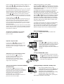 7
7
-
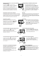 8
8
-
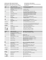 9
9
-
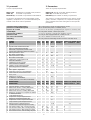 10
10
-
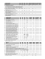 11
11
-
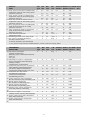 12
12
-
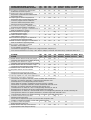 13
13
-
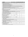 14
14
-
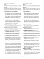 15
15
-
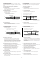 16
16
-
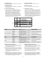 17
17
-
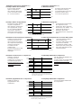 18
18
-
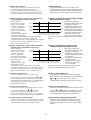 19
19
-
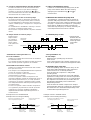 20
20
-
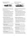 21
21
-
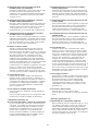 22
22
-
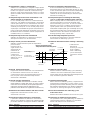 23
23
-
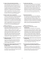 24
24
-
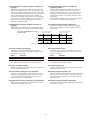 25
25
-
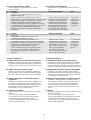 26
26
-
 27
27
-
 28
28
-
 29
29
-
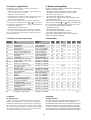 30
30
-
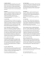 31
31
-
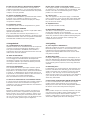 32
32
-
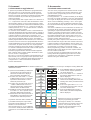 33
33
-
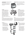 34
34
-
 35
35
-
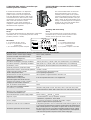 36
36
-
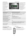 37
37
-
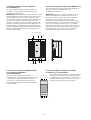 38
38
-
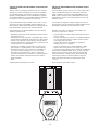 39
39
-
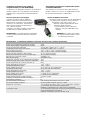 40
40
-
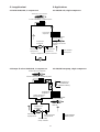 41
41
-
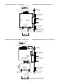 42
42
-
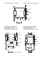 43
43
-
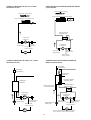 44
44
-
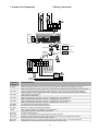 45
45
-
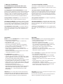 46
46
-
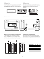 47
47
-
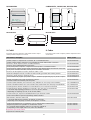 48
48
-
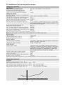 49
49
-
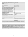 50
50
-
 51
51
-
 52
52
-
 53
53
-
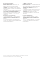 54
54
-
 55
55
-
 56
56


in altre lingue
- English: Carel mchiller compact User manual
Documenti correlati
-
Carel IRDR Series Manuale utente
-
Carel GASTEAM Manuale utente
-
Carel SmartCella 3PH WP00B24A10 Quick Manual
-
-
-
Carel humiSteam Basic Manuale utente
-
-
-
-
Altri documenti
-
Dell Stud Sensor MP2000 Manuale utente
-
Extech Instruments TL625 Manuale utente
-
Vemer FR NTC-4P3D Manuale utente
-
-
-
-
Seitron TA D022 Manuale utente
-
ACV MCBA-5 Technical Manual
-
Robertshaw Ranco ETC Two Stage Electronic Temperature Control Manuale utente
-
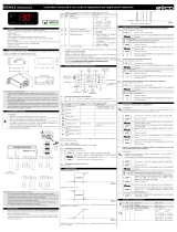 Evco EV3411M3 Instructions Sheet
