Integra Licox Brain Tissue Oxygen Monitoring IM3STEU Istruzioni per l'uso
- Tipo
- Istruzioni per l'uso

MANUFACTURER:
Integra LifeSciences Switzerland Sarl
Rue Girardet 29 (2nd Floor)
Le Locle CH-2400, Switzerland
Integra®
Licox® Brain Tissue
Oxygen Monitoring
REF IM3STEU
Instructions for Use Page 3
Instrucciones de uso Página 15
Mode d’emploi Page 27
Gebrauchsanleitung Seite 39
Istruzioni per l’uso Pagina 51
Gebruiksaanwijzing Pagina 63
BL Rev A

2
Notes

3
Instructions for Use
REF IM3STEU*
Complete Brain Probe Kit
Consisting of
REF IM3EU
Triple Lumen Introducer Kit
REF CC1SB
Oxygen Probe
REF C8B
Temperature Probe
Camino® 110-4L,
Ventrix® NL-950-SD
or
Codman® Microsensor
ICP Catheters
Are Sold Separately
* These Instructions for Use may also be used with REF IM3EU, REF CC1SB, and/or
REF C8B, packaged separately, and/or with REF IM3SEU comprised of an IM3EU
and a CC1SB.
Integra®
Licox® Brain Tissue
Oxygen Monitoring
MANUFACTURER:
Integra LifeSciences Switzerland Sarl
Rue Girardet 29 (2nd Floor)
Le Locle CH-2400, Switzerland

4
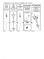
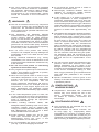
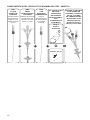
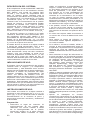
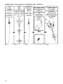
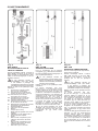
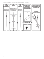
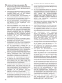
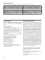
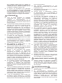
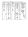
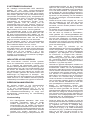
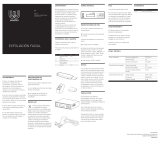
COMPONENTS OF THE PRODUCT ASSEMBLY REF IM3STEU
Fig. 1
REF
IM3EU
TRIPLE
LUMEN
INTRODUCER KIT
Three Channel
Brain Access
System with
Introducer and Bolt
Fig. 2 Fig. 3
REF
C8B
TEMPERATURE
PROBE
For
temperature
monitoring in
cerebral tissue
Camino 110-4L
Integra Ventrix
NL950-SD
NOT INCLUDED
IN THE PACKAGE:
INTRA CRANIAL
PRESSURE (ICP)
CATHETERS
COMPATIBLE
WITH IM3EU
OR
Fig. 4
COMPLETE SYSTEM
WITH OXYGEN PROBE,
ICP CATHETER
AND TEMPERATURE
PROBE,
SHOWN WITH
Ventrix NL950-SD ICP
CATHETER
- Assembly completed -
+ + + =
REF
CC1SB
OXYGEN
PROBE
For Oxygen
Pressure (pbtO2)
monitoring in
cerebral tissue

5
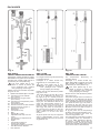
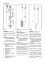
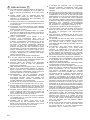
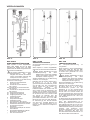
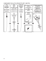
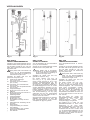
REF IM3EU
TRIPLE LUMEN INTRODUCER KIT
Packaged in a sterile double tray. When
REF IM3EU is supplied as kit with REF
CC1SB (and possibly C8B) this kit is
protected by an outer plastic bag.
This outer plastic bag is non-
sterile. It serves to protect the
inner packages from moisture
during shipping and storage.
Please remove and discard the plastic
bag prior to use.
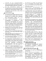
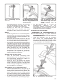
a Triple lumen introducer (Ø 1.4 mm) with:
a1 Connector for ICP catheter
(Ø <1.9 mm)
a2p Connector for oxygen probe
(Ø <0.9 mm)
a2t Connector for temperature probe
(Ø <0.9 mm)
a3 Compression seal
a4 End of lumen for the ICP catheter
a5 End of lumen for oxygen or
temperature probe
b Guide wire
c Compression cap
d Bolt
e Drill bit (Ø 5.3 mm)
f Adjustable drill stop wi-th set
screw
g Hex wrench for adjustment of
the drill stop
h Stylet
i Compressionttingfor
Ventrix ICP catheter
ii CompressionttingforCodman
ICP Microsensor catheter
j ICP obturator
PACKAGES
Fig. 5 Fig. 6 Fig. 6a
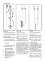
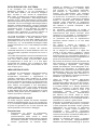
REF C8B
TEMPERATURE PROBE
For Temperature Monitoring in
Cerebral Tissue.
Packaged in a sterile double tray.
When REF C8B is supplied as kit with
REF CC1SB and IM3EU this kit is
protected by an outer plastic bag.
This outer plastic bag is non-
sterile. It serves to protect the
inner packages from moisture
during shipping and storage.
Please remove and discard the plastic
bag prior to use.
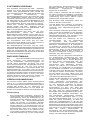
The probe (length 126 mm; Ø 0.8 mm
max) [m, n, o] is delivered (as shown
on the right [k, l]) in a protection tube [l]
which provides mechanical protection.
The probe is stiff at [n]. The probe is
connected at the rear end [m] of its
plug to the temperature monitor cable
BC10TA of the Licox CMP monitor or
of the Licox PtO2 monitor.
At [o] the probe has its temperature
sensitive area of approximately 8 mm2.
The entire protection tube must be
removed at [k] before use.
The test tube [p] is required to perform
a plausibility check as described in
the Licox CMP Operations Manual.
To perform a similar check with the
Licox PtO2 monitor, see the PtO2 probe
functionalityvericationprocedureinthe
Licox PtO2 monitor’s User’s Manual.
REF CC1SB
OXYGEN PROBE
For Oxygen Pressure (pbtO2) Monitoring
in Cerebral Tissue.
Packaged in a sterile double tray
protected by an outer plastic bag.
This outer plastic bag is non-
sterile. It serves to protect the
inner packages from moisture
during shipping and storage.
Please remove and discard the plastic
bag prior to use.
The probe (length 150 mm; Ø 0.8 mm)
[c, d, e] is delivered (as shown on
the right [a, b]) in a closed protection
tube [b], which provides mechanical
protection and protects the probe from
drying out. The calibration data for the
probe are electronically stored on a
smart card [f]. Probe and smart card
have the same number. The probe is
stiff at [d]. The probe is connected at
the rear end [c] of its plug to the pO2
monitor cable BC10PA of the Licox
CMP monitor or of the Licox PtO2
monitor.
At [e] the probe has its pbtO2 sensitive
area of approximately 13 mm2. The
entire protection tube must be removed
at [a] before use.

6
PRECAUTIONS
►These Instructions are to be used in
conjunction with the Licox CMP Operations
Manual or the Licox PtO2 monitor User’s
Manual.
►Integra intends that this device should be
used only by physicians with educational and
training background enabling the proper use
of the device.
►The Licox introducing system is intended for
useonlywiththeprobesspeciedherein.
►The Licox probes are intended for use only
withtheintroducingsystemspeciedherein.
► Licox products specied herein are intended
only for use with the Licox CMP, the Licox PtO2
monitor and all corresponding Licox cables.
►After implantation of a probe it takes
1 - 2 minutes before the local brain oxygen
tension is correctly displayed. However,
due to the micro trauma of implantation, the
initial values displayed may not represent
the oxygen tension of the surrounding tissue.
After implantation, the tissue stabilization
time (time until the oxygen tension values are
representative of the surrounding region of the
brain) may be as long as two hours.
►Do not attempt to disassemble the introducer.
►Only use probes and introducing systems if
their sterile packaging is not open, damaged
or broken.
►Only use probes and introducing systems
before their expiration date labelled on the
package.
►These devices are intended for single use
only. All components are extremely difcult
to clean after being exposed to biological
materials and adverse patient reactions may
result from reuse.
►Caution – Do not resterilize. Integra will not
be liable for any or all damages including,
but not limited to, direct, indirect, incidental,
consequential or punitive damages resulting
from or related to resterilization.
►Only use the pO2 probe which has been stored
cool at a temperature between 2ºC and 10ºC.
►Do not discard the pO2 probe packaging
before the smart card has been removed.
Probe calibration data is stored on the smart
card.
►Use only the smart card supplied with the
probe. Cross check serial number on probe
and smart card. Use of the wrong smart card
can cause measurement errors.
►Do not cut or tear the catheter body. A catheter
with a cut or torn body will no longer function.
►Only use the drill bit provided with the
introducing system. If a drill bit other than that
delivered with the kit is used, the hole may be
too large or too small.
►Do not use a power drill.
►Adequate blood coagulation must be
ensured before inserting an invasive cerebral
monitoring probe.
►In order to avoid intracranial hemorrhage, blood
coagulation must be checked before probe
insertion and must be carefully monitored
when measuring in patients in hepatic coma or
with other diseases which could impair blood
coagulation properties. This also applies to
conditions in which therapeutic maneuvers
may interfere with blood coagulation (e.g.
hypothermia, pharmacologic agents).
►If the dura mater is not opened before the
stylet is advanced, the dura mater could be
torn away from the skull, possibly resulting in
hemorrhage/hematoma.
►Inadequate opening of the dura mater may
also result in improper placement of the probe.
►The device must not be placed too near the
sagittal line in order to avoid the sagittal sinus
and major cerebral veins near the sagittal line.
►The introducer must be sealed to avoid
infection. If the seal is not made, cerebrospinal
uid may appear within the outer tube of
the introducer. The compression cap must
be tightened further to avoid leakage (see
instructions for use).
►The actual position of the sensor must be
considered for interpretation of data. It is
possible that the sensor may get displaced
from its original position.
►When monitoring is complete, remove probes
and introducer prior to bolt removal.
►The tip of the oxygen sensing catheter may
not lie in the cerebral white matter after
implantation if it is inserted in a sulcus of the
brain or in an atrophic brain. In this case the
probe may not respond to an oxygen challenge
performed after the initial stabilization time of
at least 20 min. The location of the probe may
be veried via CT scan. Remove probe if it
does not respond to the oxygen challenge or
if its tip is not within parenchyma or lies on the
surface of brain. Please note that if the probe
tip lies within the cortex, the measured oxygen
values may be higher and less stable than
measurements made with the probe tip within
the white matter.
►If the oxygen probe is placed in cerebrospinal
uid (CSF) the readings will be false high.
This may occur if the sensor is placed in the
subcortical CSF space or if it is placed in
ventricular CSF spaces, e.g. in hydrocephalic
patients.
►Only insert the oxygen, the temperature and
the ICP probes into their dedicated channels,
respectively labelled "pO2", "Temp" and "ICP".
► Use the compression tting for Ventrix ICP
catheter if using a Ventrix ICP catheter or
use the compression tting for Codman ICP
catheter if using a Codman ICP catheter.

7
► The Licox probes and introducers specied
herein have not been tested for compatibility
with Magnetic Resonnance (MR) systems.
Therefore the use of these devices in MR
environments is not recommended. Integra
should be contacted if more information is
needed.
WARNINGS
►The use of excessive force on any component
of the Licox system may cause damage and
malfunction. All mechanical features of the
Licox system can be operated without the use
of excessive force.
►The anesthetic gas halothane disturbs
measurement with all types of polarographic
oxygen sensors. After an initial exposure
time of 5 to 20 minutes, the displayed oxygen
value is overestimated; this effect is usually
reversible. However, other common anesthetic
gases such as nitrous oxide (N2O),enurane
andisouranecanbeusedwithoutimpairing
the accuracy of the measurement.
►Do not touch Licox probes with cautery
forceps or HF scalpels; this may damage the
preamplier of the Licox CMP and the Licox
PtO2 monitor.
►Strong electrical interference (e.g., during
cauterization) can cause a disturbance of the
measurement that outlasts the interference by
a few seconds.
►Do not use Licox probes or introducing
systems for more than 5 days.
►Only original Licox parts may be used with the
system. This applies in particular to probes,
cables and the power supply.
►When the front panel switch is used to input
intracranial temperature to the Licox CMP
monitor or the Licox PtO2 monitor, differences
between the set temperature and the
actual intracranial temperature will lead to
measurement errors. For example if the set
temperature is one degree higher than the
tissue temperature, the displayed oxygen
value will be underestimated by approximately
4%.
►If the C8B temperature probe is used, the
oxygen value will be correctly compensated for
tissue temperature only when the temperature
probe is inserted through the appropriate
lumen into brain tissue.
►Cables, including extension cables, with
damaged isolation jacketing must not be used.
Connector contacts must be cleaned after
coming into contact with saline solutions or body
uid. Measurement error can occur if these
recommendations are not observed.
►Probe extension cables may not be used
when their connectors are wet or damp.
Measurement errors can occur if this
recommendation is not observed.
►Do not overtighten set screw in the drill stop
(see Fig. 7) to avoid stripping the thread.
►Do not bend the probe around a radius of
curvature of less than 2 mm.
►Neurosurgery treatment facilities must be
available for monitoring related adverse
events, e.g. hemorrhage or infection.
►In rare cases, e.g. if a vessel is punctured
during implantation or when coagulation is
insufcient,hemorrhagecanoccur.Thismay
lead to a transient rise in tissue oxygen values.
Once bleeding stops tissue oxygen values are
usually decreased in surrounding non-affected
tissueifthebloodinltration surrounding the
puncture is thicker than approximately 100
μm.
►If the patient has enlarged or shifted ventricles,
the probe or its introducer may puncture the
lateral ventricle when inserted (the oxygen
probe tip reaches approximately 35 mm below
the dura level). If this occurs, the probe will
create a channel that directly connects the
ventricular system with the subarachnoid
space, bypassing the natural CSF pathways.
Because of the pressure difference between
the lateral ventricle and the subarachnoid
space, it is possible that cerebrospinal uid
fromtheventriclecouldowalongtheprobe.
The measured value will correspond to the
oxygen partial pressure of the cerebrospinal
uid and will not be representative of the
tissue.
►The user must be aware that cerebral oxygen
pressure values differ between and within
patients depending on the nature of the
damage and the individual treatment course.
It is highly recommended that users are aware
of the current knowledge relating to brain
tissue oxygen pressure (pbtO2) measurements
which has been published in the scientic
literature.
►Special consideration must be given to the
maturityoftheskullwhenusingaboltxation
in paediatric patients.
COMPLICATIONS,
ADVERSE EVENTS
►Complications associated with intracranial
sensors may occur during the use of this
device. Complications include, but are
not limited to, infection, thrombosis and
hemorrhage.
CONTRAINDICATIONS
►Licox products are not intended for any use
other than that indicated.
►Contraindications for device insertion into
the body apply, e.g. coagulopathy and/or
susceptibility to infections or infected tissue.
Aplateletcountoflessthan50000perμlis
considered a contraindication. This value may
differ according to different hospital protocols.

8
SYSTEM DESCRIPTION
The complete brain probe kit REF IM3STEU
consists of a triple lumen introducer kit REF IM3EU,
an oxygen probe REF CC1SB and a temperature
probe REF C8B. The system may be used for
simultaneous monitoring of oxygen partial pressure
(pbtO2), temperature as well as intracranial pressure
(ICP) in the cerebral white matter. For oxygen partial
pressure and temperature monitoring Licox probes
are used. For intracranial pressure (ICP) monitoring,
a Camino, Ventrix or Codman Microsensor catheter
may be used. The REF IM3STEU is used in
conjunction with the Licox CMP monitor or the Licox
PtO2 monitor.
The oxygen probe is inserted into brain tissue
through the "pO2" labelled channel of the triple
lumen introducer REF IM3EU to a depth of
approximately 35 mm below the dura (Fig. 17). The
probe’s oxygen sensing part starts 4 to 6 mm from
the tip of the probe.
The ICP catheter is inserted into brain tissue
through the "ICP" labelled channel to an adjustab-
le depth of 0 mm to 12 mm.
The temperature probe is inserted through
the "temp" labelled channel of the triple lumen
introducer. When inserted the tip of the temperature
probe is located 1 to 3 mm past the end of the ICP
catheter. The system is designed for no more than
vedaysofcontinuousmonitoring.
INDICATIONS FOR USE
The Licox Brain Oxygen Monitoring System
measures intracranial oxygen and temperature
and is intended as an adjunct monitor of trends of
these parameters, indicating the perfusion status
of cerebral tissue local to sensor placement. Licox
System values are relative within an individual, and
should not be used as the sole basis for decisions as
to diagnosis or therapy. It is intended to provide data
additional to that obtained by current clinical practice
in cases where hypoxia or ischemia are a concern.
INSTRUCTIONS FOR USE
The probes are inserted into the brain tissue via
an introducer (Fig. 5, a, b, c) and bolt (Fig. 5, d).
The introducer seals the system hermetically at
the connection to the bolt and provides mechanical
protection and strain-relief to the probes.
Preparation
• Select an insertion site. Positioning of the
probes must be given careful consideration
due to the hetero-geneity of the oxygen
partial pressure in brain tissue. The probes
should be placed in viable tissue, when
monitoring oxygen availability. Viable tissue
may be found in a peri-focal lesion, e.g. the
penumbra, or in undamaged tissue, e.g. the
contra lateral side of a focal lesion. The probe
should not be placed into a hematoma or
non-vital tissue. The user should be aware of
the current issues in the pertaining scientic
literature when making the choice of catheter
placement and for interpretation of the oxygen
measurements obtained.
• If possible, place the probe 20 – 40 mm off
the midline, just anterior to the coronal suture.
Other locations may be chosen according to
the location of a lesion.
• The position of the drill hole should be at least
10 mm away from other probes.
• To reduce the risk of infection, the use of
depilatory agents or no hair removal is
recommended.
• If shaving or clipping is performed it should
be done immediately before the operation,
preferably with electric clippers. The scalp
should be free of gross contamination.
• To minimize the risk of surgical site
infections, it is recommended to prepare the
surgical area in accordance with evidence-
based guidelines, such as Mangram et al.
Guideline for Prevention of Surgical Site
Infection, 1999. Infection Control and Hospital
Epidemiology, 20(4), pp. 257-258, and Nichols
RL. Preventing Surgical Site Infections: A
Surgeon’s Perspective. Emerging Infectious
Diseases. 7(2), Mar-Apr 2001.
• Use an appropriate antiseptic agent for
preoperative preparation of the skin at the
incision site. Members of the surgical team
who have direct contact with the sterile
operating eld or sterile instruments or
supplies used in the eld, should wash their
hands and forearms by surgical scrubbing
immediately before the procedure for at least
2-5 minutes. After scrub, keep hands up and
away from body. Dry hands with a sterile towel
then don a sterile gown and gloves.
• Apply an antiseptic in concentric circles,
beginning in the area of the proposed incision.
The prepared area should be large enough to
extend the incision or create new incisions,
if necessary. The skin preparation procedure
may need to be modied depending on the
condition of the skin or location of the incision
site.
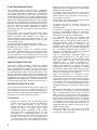
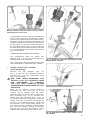
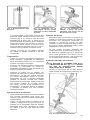
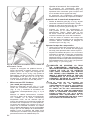
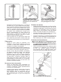
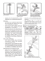
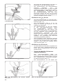
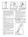
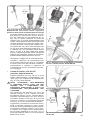
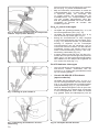
• Estimate the thickness of the skull and adjust
the drill stop accordingly. Loosen the drill stop
(Fig. 5, f) with the hex wrench (Fig. 5, g) about
half to one turn, so that the set screw is still in
the groove of the drill-bit (Fig. 5, e). Rotate the
drill stop around the drill-bit (Fig. 7) until the
exposed tip of the drill-bit is just long enough
to completely drill through the skull with its
inner table. The tip of the drill-bit should not
penetrate the inner table by more than 1 mm.
Tighten the drill stop.
• Attach the drill-bit to a hand drill. Do not use
a powered drill, such as those driven by
compressed air or electricity.

9
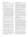
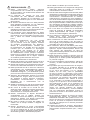
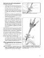
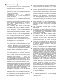
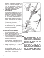
Fig. 7: Adjustment of the drill
stop
Fig. 8: Distance to the sagittal
line >20 mm; scalp may be
sutured to bolt
Fig. 9: Insertion of stylet
through the bolt ensures a
good pathway for the probe
Drilling
• Drape the shaved and prepared area.
Inltrating in the area of the incision
subcutaneously with a local anaesthetic is a
surgical option.
• Make a small linear incision carrying it to the
bone. A self-retaining retractor is then inserted
to provide good bone exposure.
• Drill the hole. Do not change the direction of
the drill while drilling, this could cause the hole
to become too wide or conical. Ensure that the
twist drill hole extends through the inner table
of the skull exposing the dura. Care must be
taken when penetrating the inner table of the
skull, to prevent damage to the dura or brain.
Remove the drill and rinse the hole with sterile
isotonic solution.
Dura mater opening
• Open the dura mater carefully by using an
appropriate blade to make a cruciate incision,
securing haemostasis is necessary.
• Irrigate the skull hole with sterile isotonic
solution and make sure that the entry site
in the dura is of adequate size to allow the
catheters to pass through without bending,
and that it is cleared of any debris.
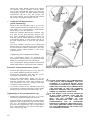
Fixation of the bolt
• Thread the bolt into the hole. Fig. 8 and Fig.
9 illustrate proper placement. Should undue
resistance be encountered, do not use
excessive force. If necessary, drill the inner
table again. If the bolt is too loose a new hole
must be drilled.
• The skin may be sutured around the shaft of
the bolt, at location [a] in Fig. 8.
• The stylet (Fig. 5, h) is advanced through
the bolt to ensure a good pathway for the
introducer and for the probes (Fig. 9); the
stylet is then removed.
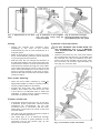
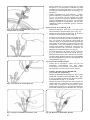
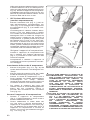
Insertion of the introducer
DO NOT REMOVE THE GUIDE WIRE OR
ICP OBTURATOR, (Fig. 5, b, j) BEFORE
THE INTRODUCER IS INSERTED INTO
THE BOLT.
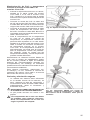
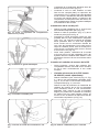
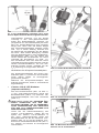
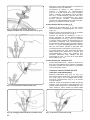
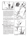
• Hold the introducer by the outer tube above
the compression cap (see Fig. 10). Rotate until
the seal ts into the bolt channel and then
insert it as far as possible into the bolt. Then
the introducer tip reaches approximately 20
mm (Fig.17) out of the bolt.
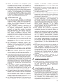
Fig. 10: Insertion of the introducer

10
• Continue to hold outer tube and rotate the
compression cap (Fig.11) clockwise one full
turn (360°). The introducer should now be
loosely attached to the bolt. The compression
cap must not be tightened yet, as this will
prevent removal of the guide wire and
insertion of the probes.
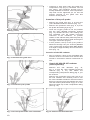
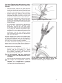
Insertion of the pbtO2 probe
• Remove the guide wire (Fig. 5, b) from the
"pO2" labelled introducer channel. (Fig. 12).
• Remove the protection tube (Fig. 6, b) from
the probe at location [a] in Fig. 6.
• Insert the oxygen probe as far as possible
into the "pO2" labelled introducer channel
(Fig. 13). Rotate the blue, free rotating lock
ring clockwise onto the female Luer-type
connector of the introducer. To prevent
rotation of the catheter body hold the probe by
its white connector housing while securing the
Luer-type connection (Fig.14).
• In this position, the tip of the pbtO2 probe is
advanced through the pO2 channel (labelled
"pO2") of the brain access system REF IM3EU
to a depth of approximately 35 mm below the
dura (Fig. 17).
Insertion of the ICP catheter
• Prior to insertion, each of the compatible ICP
sensors must be connected to its monitor and
zeroed in accordance with its instructions for
use.
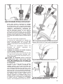
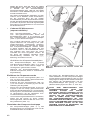
• Ventrix NL950-SD ICP catheter
(sold separately
Remove the ICP obturator (Fig. 15,
Fig. 5, j) from the "ICP" labelled introducer
channel (Fig. 5, a1) and attach the
correspondingcompressiontting(Fig.5,i)to
the channel.
Remove the protection tube from the tip of
the ICP catheter and carefully insert it into
the "ICP" labelled introducer channel until the
rstring(countingfromthecathetertip)ofthe
150 mm marker (three black rings), is 12 mm
abovethebluecapofthecompressiontting
(see Fig. 16).
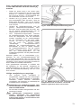
Fig. 12: Remove the guide wire
Fig. 11: Attach compression screw cap
loosely (1 turn)
Fig. 13: Insert the pbtO2 probe
Fig. 14: Fix the probe at the Luer connector Fig. 15: Remove the ICP obturator

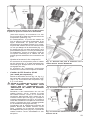
11
In this position the tip of the ICP catheter lies
at the level of the dura. Advancing it further
will bring the catheter tip into the cranial cavity.
Normally, the tip of the Ventrix NL950-SD ICP
catheter is advanced 12 mm below the level of
the dura (Fig. 17). The ICP catheter should not
be advanced deeper than 15 mm below the
dura because the local tissue irritation induced
by the ICP catheter could cause artifacts in the
pbtO2 measurement.
Tightening the compression tting
The compression tting for Ventrix ICP
catheter (Fig. 5, i) must be closed tightly by
rotating its blue cap clockwise.
Thecompression ttingprovides mechanical
strain-relief when it compresses the catheter.
• Camino 110-4L ICP catheter
(sold separately)
Remove the ICP obturator (Fig. 18;
Fig. 5, j) from the "ICP" labelled introducer
channel(Fig. 5, a1).The compression tting
(Fig. 5, i) is not used.
USE CARE WHEN REMOVING THE
Camino 110-4L ICP CATHETER FROM
THE PACKAGING TO PREVENT
THE Licox BOLT ADAPTER FITTING
COMPONENTS FROM SLIDING OFF THE
CATHETER.
Refer to the Camino 110-4L catheter´s
instructions for use. Insert the tip of the
Camino 110-4L catheter into the "ICP"
labelled introducer lumen until its male Luer-
type connector (Fig. 19, a) contacts the
female Luer-type connector (Fig. 5, a1) on
the introducer channel. Engage the male and
female Luer-type connectors and tighten by
rotating in a clockwise direction. Verify that
the shoulder of the white plastic sleeve on
the Camino 110-4L catheter makes contact
with the Bolt Adapter Fitting compressor
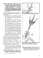
cap (Fig.19). The tip of the Camino 110-4L
catheter will extend beyond the bolt 15 mm.
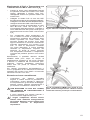
Fig. 16: Prior to advancing the Ventrix NL950-
SD ICP catheter into the cranial cavity, its tip is
adjusted at the dura level
Fig. 18: Remove the ICP obturator
Fig. 19: Maximum insertion of the Camino 110-4L
ICP catheter
Fig. 17: Ready for measurement with the Ventrix
NL950-SD ICP catheter

12
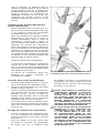
Grasp the white plastic sleeve and retract
the Camino 110-4L catheter until the black
ring on the white plastic sleeve (a in Fig. 20)
is exposed. Tighten the Bolt Adapter Fitting
compressor cap (b in Fig. 20). Finally, the
tip of the Camino 110-4L catheter will extend
beyond the bolt approximately 12 mm.
• Codman ICP Microsensor
(sold separately)
Remove the ICP obturator (Fig. 5, j) from the
"ICP" labelled introducer channel (Fig. 5, a1)
and attach the corresponding compression
tting(Fig.5,ii)tothechannel.
Mark the Codman Microsensor catheter 155
mm from the tip and carefully insert it into
the "ICP" labelled introducer channel so
that the mark is visible above the cap of the
compressiontting.In this positionthe tip of
the ICP catheter lies 15 mm into the cranial
cavity.
The ICP catheter should not be advanced
deeper than 15 mm below the dura because
the local tissue irritation induced by the ICP
catheter could cause artifact in the pbtO2
measurement.
Tightening the compression tting
The compression tting for Codman ICP
Microsensor catheter (Fig. 5, ii) must be closed
tightly by rotating its blue cap clockwise.
Thecompression ttingprovides mechanical
strain-relief when it compresses the catheter.
Insertion of the temperature probe
• Remove the guide wire (Fig 5, b, Fig. 12) from
the "Temp" labelled introducer channel.
• Remove the protection tube (Fig. 6a, l) from
the probe at location [k] in Fig. 6a.
• Insert the temperature probe as far as
possible into the "Temp" labelled introducer
channel. Rotate the green, free rotating lock
ring clockwise onto the female Luer-type
connector of the introducer.
• To prevent rotation of the catheter body hold
the probe by its white connector housing while
securing the Luer-type connection (Fig. 14).
Tightening of the compression cap
• Rotate the compression cap (Fig. 5, c) of the
introducer clockwise tightly onto the bolt.
• Hold the wings of the bolt with one hand while
tightening the compression cap with the other
(Fig. 21). The distance between the wings of
the bolt and compression cap is small when
tight, approximately 2 mm (see location [a] in
Fig. 17 and in Fig. 22).
AFTER TIGHTENING THE COMPRESSION
CAP, CHECK THE ASSEMBLY FOR CSF
LEAKAGE. IF A LEAK IS NOTED, HOLD
THE WINGS OF THE BOLT FIRMLY IN ONE
HAND AND TIGHTEN THE COMPRESSION
CAP FURTHER. IF THE CSF LEAKAGE
PERSISTS, REMOVE THE ASSEMBLY IN
ORDER TO PREVENT INFECTION.
IN THE EVENT THAT AN ICP CATHETER
IS NOT USED, ENSURE THAT THE ICP
OBTURATOR (Fig. 5, j) IS INSERTED
INTO THE ICP CHANNEL OF THE
IM3EU INTRODUCER AND THAT THE
COMPRESSION CAP IS TIGHTENED
ENOUGH TO PREVENT LEAKAGE OF CSF.
THIS MAY REQUIRE MORE ROTATIONS
OF THE COMPRESSION CAP THAN IF AN
ICP CATHETER IS USED.
Fig. 20: Ready for measurement with the
Camino 110-4L ICP catheter

13
Fig. 21: Tighten compression seal
PbtO2 and Temperature Monitoring using
the Licox CMP monitor or the Licox PtO2
monitor
• Insert the smart card into the smart card slot
on the front panel of the Licox CMP monitor or,
if using the Licox PtO2 Monitor, into the smart
card slot on the right panel of the PtO2 monitor.
• Connect the PbtO2 probe to the blue pO2
monitor cable REF BC10PA. Connect the
cable REF BC10PA to the blue oxygen input
socket of the CMP monitor or PbtO2 monitor.
• Connect the temperature probe to the green
temperature monitor cable REF BC10TA.
Connect the cable REF BC10TA to the green
temperature input socket of the CMP monitor
or PtO2 monitor.
• For temperature compensation if temperature
probe is not used the patient’s brain
temperature must be set at the code switch
on the front panel of the Licox CMP monitor
or by using the "Manual Temperature Input"
controls on the Licox PtO2 monitor. If the brain
temperature is not available the patient’s core
temperature may be used instead. Please
note that patient’s brain and core temperature
may not be the same.
Normally, reliable pbtO2 readings are available after
a tissue stabilization time of 20 minutes (when
the tissue has stabilized after the microtrauma of
implantation). However, it may occasionally take
up to two hours until the readings stabilize.
For related information regarding set up and use
please refer to the Licox CMP monitor operations
manual or the Licox PtO2 Monitor User’s Manual.
Safe Removal and Disposal
• Removal of the system should occur in
reverse order of the insertion, i.e. loosen
the compression cap and ttings, remove
each catheter individually, then remove the
introducerandnallythebolt.
DO NOT REMOVE THE BOLT FROM THE
PATIENT WITH THE INTRODUCER STILL
IN PLACE.
• The skin may be closed with a suture or staples.
The single use components must be
handled as biohazardous material.
Dispose off the single use components
according to the hospital policy.
Fig. 22: IM3EU Introducer with oxygen probe,
temperature probe and Camino 110-4L ICP
catheter inserted, ready for measurement

14
PRODUCT INFORMATION DISCLOSURE
INTEGRA HAS EXERCISED REASONABLE
CARE IN THE CHOICE OF MATERIALS AND
MANUFACTURE OF THIS PRODUCT. INTEGRA
EXCLUDES ALL WARRANTIES, WHETHER
EXPRESSED OR IMPLIED BY OPERATION
OF LAW OR OTHERWISE, INCLUDING, BUT
NOT LIMITED TO ANY IMPLIED WARRANTIES
OF MERCHANTABILITY OR FITNESS FOR A
PARTICULAR PURPOSE. INTEGRA SHALL
NOT BE LIABLE FOR ANY INCIDENTAL OR
CONSEQUENTIAL LOSS, DAMAGE, OR
EXPENSE, DIRECTLY OR INDIRECTLY ARISING
FROM USE OF THIS PRODUCT. INTEGRA
NEITHER ASSUMES NOR AUTHORIZES ANY
PERSON TO ASSUME FOR IT ANY OTHER OR
ADDITIONAL LIABILITY OR RESPONSIBILITY
IN CONNECTION WITH THESE PRODUCTS.
INTEGRA INTENDS THAT THIS DEVICE
SHOULD BE USED ONLY BY PHYSICIANS WITH
EDUCATIONAL AND TRAINING BACKGROUND
ENABLING THE PROPER USE OF THE DEVICE.
HOW SUPPLIED
Licox Brain Tissue Oxygen Monitoring Probes
and Introducer Kits are supplied sterile and non-
pyrogenic in a double-wrap packaging.
RETURN POLICY
Authorization from customer service must be
obtained prior to returning product.
No product return is accepted except if previously
agreed by Integra in the framework of a complaint.
Determination of a product defect will be made by
Integra.
All products can be ordered through your Integra
Sales Specialist.
Customer Service Contact Information
Integra LifeSciences Corporation
1100 Campus Road
Princeton, NJ 08540, U.S.A.
Telephone: 1-800-654-2873
Outside US: +1-609-275-0500
Fax: +1-609-275-5363
Service and Repair
For service, repair or replacements,
contact your local Integra representative.
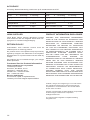
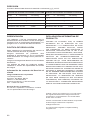
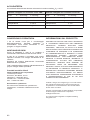
ACCURACY
Accuracy determined during continuous pbtO2 measurement at 37ºC.
When connected to Licox CMP monitor When connected to Licox PtO2 monitor
pbtO2 0 - 20 mmHg ± 2 mmHg pbtO2 0 - 20 mmHg ± 2 mmHg
pbtO2 21 - 50 mmHg ± 10% pbtO2 21 - 50 mmHg ± 10%
pbtO2 51 - 150 mmHg ± 13% pbtO2 51 - 150 mmHg ± 13%
Temperature ± 0.2°C Temperature ± 1°C
Max. Duration of Use 5 days Max. Duration of Use 5 days
Codman, Integra, the Integra logo, Licox and Ventrix
are registered trademarks of Integra LifeSciences
Corporation or its subsidiaries in the United States
and/or other countries.
Camino is a trademark of Natus Medical Incorporated.
© 2022 Integra LifeSciences Corporation.
All Rights Reserved.
U.S. Patent www.integralife.com/patentmarking
integralife.com

15
Instrucciones de uso
REF IM3STEU*
Kit Completo de Sonda Cerebral
Composición
REF IM3EU
Kit Introductor de Trilumen
REF CC1SB
Sonda de Oxígeno
REF C8B
Sonda de Temperatura
Los Catéteres de Presión Intracraneal
Camino® 110-4L,
Ventrix® NL-950-SD
o
Codman® Microsensor
se venden por separado
FABRICANTE:
Integra LifeSciences Switzerland Sarl
Rue Girardet 29 (2nd Floor)
Le Locle CH-2400, Switzerland
* Estas instrucciones de uso pueden aplicarse también con REF IM3EU, REF CC1SB
y/o REF C8B, envasadas por separado, y/o con REF IM3SEU compuesta de un
IM3EU y un CC1SB.
Integra®
Licox® Brain Tissue
Oxygen Monitoring
®

16
COMPONENTES DEL PRODUCTO ENSAMBLADO REF IM3STEU
REF
IM3EU
INTRODUCTOR
TRILUMEN
Sistema de acceso
cerebral de tres
canales con intro-
ductor y perno
REF
C8B
SONDA DE
TEMPERATURA
Para la
monitorización
de temperature
en el tejido
cerebral
Camino 110-4L
Integra
Ventrix
NL950-SD
EL PAQUETE NO
INCLUYE:
CATÉTERES
DE PRESIÓN
INTRACRANEAL
(PIC)
COMPATIBLES
CON IM3EU
O
SISTEMA COMPLETO
CON SONDA DE
OXÍGENO, CATÉTER
DE PIC Y SONDA
DE TEMPERATURA
MOSTRADO CON
CATÉTER DE PIC
NL950-SD Ventrix
- Montaje terminado -
+ + + =
REF
CC1SB
SONDA DE
OXÍGENO
monitorización
de presión de
oxígeno en el
tejido cerebral
(PbtO2)

17
REF IM3EU
KIT INTRODUCTOR TRILUMEN
Envasado en una doble bandeja
estéril. Cuando REF IM3EU es
suministrado como kit con REF CC1SB
(y posiblemente C8B), este kit está
protegida por una bolsa de plástico
externa.
ESTA BOLSA EXTERNA DE
PLÁSTICO NO ES ESTÉRIL.
SIRVE PARA PROTEGER LOS
ENVASES INTERIORES DE LA
HUMEDAD DURANTE EL TRANS-
PORTE Y EL ALMACENAJE.
Quitar y echar la bolsa de plástico
antes de utilizar.
a Introductor trilumen (Ø 1,4 mm) con:
a1 Conector para catéter de PIC
(Ø <1,9 mm)
a2p Conector para sonda de oxígeno
(Ø <0,9 mm)
a2t Conector para sonda de
temperatura (Ø <0,9 mm)
a3 Junta de compresión
a4 Punta para el catéter de PIC
a5 Punta para la sonda de oxígeno
o temperatura
b Alambre guía
c Tapa de compresión
d Perno
e Broca (Ø 5,3 mm)
f Tope de broca graduable con
tornillojador
g Llave hexagonal para graduar el
tope de broca
h Estilete
i Accesorio de compresión para
catéter de PIC Ventrix
ii Accesorio de compresión para catéter
de Microsensor PIC Codman
j Obturador de PIC
PAQUETES
Fig. 5 Fig. 6 Fig. 6a
REF C8B
SONDA DE TEMPERATURA
Para la monitorización de la
temperatura en el tejido cerebral.
Envasado en una doble bandeja estéril.
Cuando REF C8B es suministrado
como kit con REF CC1SB y IM3EU,
este kit está protegida por una bolsa de
plástico externa.
ESTA BOLSA EXTERNA DE
PLÁSTICO NO ES ESTÉRIL.
SIRVE PARA PROTEGER LOS
ENVASES INTERIORES DE LA
HUMEDAD DURANTE EL TRANS-
PORTE Y EL ALMACENAJE.
Quitar y echar la bolsa de plástico
antes de utilizar.
El catéter (longitud 126 mm; Ø máximo
0,8 mm) [m, n, o] se suministra (tal
como se muestra a la derecha) [k, l])
dentro de un tubo de protección [l] que
proporciona protección mecánica. El
catéter es rígido en [n]. El extremo
posterior [m] del conector del catéter
se conecta al cable del monitor de
temperatura BC10TA del monitor
Licox CMP o del monitor Licox PtO2.
En [o] el sensor tiene su área sensible
de temperatura de aproximadamente
8 mm2. Debe retirarse todo el tubo de
protección en [k] antes de usar.
El tubo de ensayo[p] se requiere para
efectuar una prueba de plausibilidad
tal como se describe en el Manual
de Uso de Licox CMP. Para realizar
un chequeo similar con el monitor
Licox PtO2 véa el procedimiento de
vericación de funcionalidad de la
sonda PtO2 en el manual del usuario
del monitor Licox PtO2.
REF CC1SB
SONDA DE OXÍGENO
Para la monitorización de presión de
oxígeno en el tejido cerebral (pbtO2):
Envasado en una doble bandeja estéril
protegida por una bolsa de plástico
externa.
ESTA BOLSA EXTERNA DE
PLÁSTICO NO ES ESTÉRIL.
SIRVE PARA PROTEGER LOS
ENVASES INTERIORES DE
LA HUMEDAD DURANTE EL
TRANSPORTE Y EL ALMA-
CENAJE.
Quitar y echar la bolsa de plástico
antes de utilizar.
La sonda (longitud 150 mm; Ø 0,8 mm)
[c, d, e] se suministra (tal como se
muestra a la derecha) dentro de un
tubo de protección cerrado [b], que
proporciona protección mecánica e
impide que la sonda se seque. Los
datos de calibración del catéter se
almacenan electrónicamente en una
tarjeta electrónica inteligente [f]. La
sonda y la tarjeta electrónica tienen el
mismo número. El sonda es rígida en
[d]. El extremo posterior [c] del conector
de la sonda se conecta al cable del
monitor de pO2 BC10PA del monitor
Licox CMP o del monitor Licox PtO2.
En [e] el sensor tiene su área sensible
de pbtO2 de aproximadamente 13 mm2.
Debe retirarse todo el tubo de
protección en [a] antes de usar.

18
PRECAUCIONES
►Estas instrucciones deben seguirse
conjuntamente con el Manual de Operación
de Licox CMP o con el Manual del Usuario de
monitor Licox PtO2.
►La intención de Integra es que este
instrumento tan sea utilizado únicamente
por médicos dotados de la educación y la
formación necesarias para el uso adecuado
del producto.
►El sistema introductor de Licox está pensado
para utilizarse únicamente con los catéteres
especicadosenestasinstrucciones.
►Las sondas Licox están pensadas para
utilizarse únicamente con el sistema introductor
especicadoenestasinstrucciones.
► Los productos Licox especicados en estas
instrucciones están pensados para utilizarse
únicamente con el Licox CMP, el monitor Licox
PtO2 y todos los cables correspondientes
Licox.
►Tras la implantación de una sonda
transcurren entre 1 y 2 minutos antes de
que la presión local del oxígeno cerebral
se muestre correctamente. Sin embargo,
debido al microtraumatismo causado por
la implantación, es posible que los valores
iniciales que se muestran no equivalgan
a la presión del oxígeno en el tejido
circundante. Tras la implantación, el tiempo
de estabilización tisular (tiempo necesario
hasta que los valores de presión del oxígeno
sean representativos de la región cerebral
circundante) puede alcanzar dos horas.
►No intentar desmontar el introductor.
►Utilizar las sondas y los introductores sólo si el
envase estéril no está abierto, dañado o roto.
►Utilizar las sondas y los introductores antes de
la fecha de caducidad indicada en el envase.
►Estos productos son de un solo uso. Todos sus
componentes son extremadamente difíciles
de limpiar después de quedar expuestos a
materiales biológicos, y su reutilización puede
provocar reacciones adversas en los pacientes.
►Atención: No reesterilizar. Integra no se porta
responsable de ningún daño, inclusive pero
sin limitarse a daños directos, indirectos,
incidentales, consecuenciales o punitivos
derivados de o relacionados con la
reesterilización.
►Utilizar la sonda de pO2 sólo si fue almacenada
en fresco, a una temperatura de entre 2 y 10ºC.
►No echar el envase de la sonda de pO2
antes de haber retirado la tarjeta electrónica.
Los datos de calibración del catéter están
almacenados en la tarjeta electrónica.
►Utilizar únicamente la tarjeta electrónica
suministrada con el catéter. Cotejar los
números de serie del catéter y de la tarjeta
electrónica. Utilizar una tarjeta equivocada
puede ocasionar errores de medición.
►No cortar ni rasgar el cuerpo del catéter. Un
catéter con el cuerpo cortado o rasgado no
funcionará.
►Utilizar únicamente la broca suministrada
con el sistema de introducción. Si se emplea
una broca distinta de la que se suministra
conelkit,eloricioresultantepuederesultar
demasiado grande o demasiado pequeño.
►No utilizar un taladro que no sea manual.
►Debe garantizarse una coagulación sanguínea
adecuada antes de insertar una sonda de
monitorización cerebral invasiva.
► Andeevitarhemorragiasintracraneales,debe
vericarselacoagulaciónsanguíneaantesde
la inserción de la sonda. La coagulación debe
monitorizarse cuidadosamente al efectuar
mediciones en pacientes en coma hepático o
con otras enfermedades capaces de deteriorar
las propiedades de la coagulación sanguínea.
Ello se aplica también a situaciones en las que
las maniobras terapéuticas puedan interferir
con la coagulación sanguínea (tales como la
hipotermia o ciertos agentes farmacológicos).
►Si no se abre una incisión en la duramadre
antes de avanzar el estilete, la duramadre
podría desprenderse del cráneo y llegar a
causar una hemorragia/un hematoma.
►Una apertura inadecuada de la duramadre
puede tener como consecuencia una
colocación inadecuada de la sonda.
►El instrumento no debe situarse demasiado
cerca de la línea sagital, a n de evitar el
seno sagital y las principales venas cerebrales
ubicadas cerca de la línea sagital.
►El introductor debe ser hermético para evitar
infecciones. Si la junta no es hermética, puede
aparecer líquido cefalorraquídeo dentro del
tubo exterior del introductor. La tapa de
compresióndebeapretarsemásandeevitar
fugas (ver instrucciones).
►Debe tenerse en cuenta la posición real del
sensor para la interpretación de los datos. Es
posible que el sensor pueda desplazarse de
su posición original.
►Una vez complida la monitorización, retirar las
sondas y el tubo introductor antes de retirar
el perno.
►Es posible que la punta del sensor de oxígeno
no quede ubicada en la sustancia blanca
cerebral tras la implantación si se inserta
en un surco del cerebro o en un cerebro
atróco. En tal caso, cabe la posibilidad
de que la sonda no responda a una prueba
de exposición a oxígeno efectuada tras un
tiempo inicial de estabilización de al menos
20 minutos. La ubicación del catéter puede
vericarse mediante TAC. Retirar la sonda
si no responde a la prueba de exposición a
oxígeno o si la punta no se encuentra dentro
del parénquima o yace en la supercie del
cerebro. Debe tenerse en cuenta que si la
punta del catéter se encuentra dentro del
córtex, los valores medidos de oxígeno
pueden ser más elevados y menos estables
que las mediciones efectuadas cuando la
punta de la sonda se encuentra dentro de la
sustancia blanca.
►Si la sonda de oxígeno se coloca en líquido
cefalorraquídeo (LCR), las lecturas serán
falsamente elevadas. Ello puede ocurrir si el
sensor se coloca en el espacio subcortical del
LCR o si se ubica en espacios ventriculares
de LCR, por ejemplo en el caso de pacientes
hidrocefálicos.
►Insertar las sondas de oxígeno, temperatura
y PIC únicamente en sus canales dedicados,
denominados respectivamente "pO2", "Temp"
e "ICP".

19
►Utilizar el accesorio de compresión para
el catéter de PIC Ventrix si se emplea un
catéter de PIC Ventrix. Utilizar el accesorio de
compresión para catéter de PIC Codman, si
se emplea un catéter de PIC Codman.
► LassondasLicoxeintroductoresespecicados
en este documento no han sido probados en
cuanto a la compatibilidad con los sistemas
de resonancia magnética (RM). Por lo tanto
no se recomienda el uso de estos dispositivos
en entornos de RM. Póngase en contacto con
Integra, si necesita más informaciones.
ADVERTENCIAS
►El uso de una fuerza excesiva en cualquiera
de los componentes del sistema Licox puede
ocasionar daños y fallos de funcionamiento.
Todas las características mecánicas del
sistema Licox pueden utilizarse sin emplear
un exceso de fuerza.
►El gas anestésico halotano distorsiona la
medición con todos los tipos de sensores
de oxígeno polarográcos. Después de
un tiempo de exposición inicial de 5 a 20
minutos, el valor de oxígeno mostrado
está sobreestimado; dicho efecto suele ser
reversible. Sin embargo, pueden utilizarse
otros gases anestésicos comunes tales
como el óxido nitroso (N2O),elenuranoyel
isouranosinponerenpeligrolaprecisiónde
la medición.
►No tocar los catéteres Licox con pinzas
de cauterización ni con bisturíes de alta
frecuencia; ello puede dañar el sistema de
preamplicacióndelLicoxCMPydelmonitor
Licox PtO2.
►Las interferencias eléctricas fuertes (por
ejemplo durante la cauterización) pueden
ocasionar una perturbación de la medición
que persiste unos segundos más que la
interferencia.
►No utilizar las sondas ni los sistemas
introductores Licox durante más de cinco
días.
►Sólo deben utilizarse piezas Licox originales
con el sistema. Ello se aplica en particular a
sondas, cables y la fuente de alimentación.
►Si se utiliza el interruptor del panel frontal para
entrar la temperatura intracraneal en el monitor
del Licox CMP o en el monitor del Licox PtO2,
las diferencias entre la temperatura jada y
la temperatura intracraneal real ocasionará
errores de medición. A título de ejemplo, si la
temperatura entrada es un grado más elevada
que la temperatura tisular, el valor de oxígeno
mostrado se subestimará aproximadamente
en un 4%.
►Si se utiliza la sonda de temperatura C8B,
el valor del oxígeno quedará compensado
correctamente para la temperatura tisular sólo
si la sonda de temperatura se inserta en el
tejido cerebral a través del canal apropiado.
►No deben utilizarse los cables, inclusive los
de prolongación, con el revestimiento aislante
dañado. Los contactos de los conectores
deben limpiarse tras entrar en contacto
con soluciones salinas o uidos corporales.
Pueden producirse errores de medición si no
se siguen estas recomendaciones.
►Los cables prolongadores de las sondas no
deben utilizarse si sus conectores están
mojados o húmedos. Pueden producirse
errores de medición si no se sigue esta
recomendación.
► Noapretaren excesoel tornillojador enel
topedebroca(véaseg.7)paraevitarquese
pase de rosca.
►No doblar el catéter alrededor de un radio de
curvatura inferior a 2 mm.
►Es necesario tener a disposición equipos de
tratamiento neuroquirúrgico para monitorizar
efectos adversos relacionados, tales como
hemorragia o infecciones.
►En raras ocasiones, por ejemplo si se perfora
un vaso sanguíneo o si la coagulación es
insuciente, pueden producirse hemorragias.
Ello puede ocasionar un aumento transitorio
de los valores de oxígeno tisular. En cuanto se
detiene la hemorragia, los valores de oxígeno
tisular suelen descender en los tejidos
circundantesnoafectadossilainltraciónde
sangre alrededor de la perforación tiene un
grosorsuperioraunos100μm.
►Si el paciente tiene ventrículos engrosados
o desplazados, es posible que la sonda o su
introductor perforen el ventrículo lateral al
insertarse (la punta de la sonda de oxígeno
llega uno 35 mm por debajo de la duramadre).
Si ello ocurre, la sonda creará un canal que
conectará directamente el sistema ventricular
con el espacio subaracnoideo, evitando
las rutas naturales del LCR. A causa de la
diferencia de presión entre el ventrículo lateral
y el espacio subaracnoideo, es posible que
uya líquido cefalorraquídeo del ventrículo
por la sonda. El valor medido corresponderá
a la presión parcial de oxígeno del líquido
cefalorraquídeo y no será representativo del
tejido.
►El usuario debe recordar que los valores de
lapresióntisulardeloxígenocerebraldieren
entre pacientes y también en un mismo
paciente según la naturaleza del daño y el
curso terapéutico individual. Se recomienda
encarecidamente que los suarios estén al
día de los conocimientos actuales acerca de
la medición de la presión tisular del oxígeno
cerebral (pbtO2) publicados en la bibliografía
cientíca.
►Debe prestarse especial atención a la
madurez del cráneo al emplear una jación
con perno en pacientes pediátricos.
COMPLICACIONES,
EFECTOS ADVERSOS
►Pueden producirse complicaciones asociadas
a los sensores intracraneales durante el uso
de este instrumento. Las complicaciones
incluyen, pero no se limitan a infecciones,
trombosis y hemorragias.
CONTRAINDICACIONES
►Los productos Licox no están pensados para
ningún otro uso que el indicado.
►Son aplicables las contraindicaciones propias
para la inserción de instrumentos en el cuerpo,
tales como coagulopatía y/o susceptibilidad a
las infecciones o a los tejidos infectados. Un
recuento plaquetario inferior a 50.000 por µl
se considera una contraindicación. Dicho
valor puede variar en función de los protocolos
hospitalarios correspondientes.

20
DESCRIPCIÓN DEL SISTEMA
El kit completo de sonda cerebral REF IM3STEU
está compuesto de un kit introductor trilumen
REF IM3EU, una sonda de oxígeno REF
CC1SB y una sonda de temperatura REF
C8B. El sistema puede utilizarse para la
monitorización simultánea de la presión parcial
de oxígeno (pbtO2), la temperatura y la presión
intracraneal (PIC) en la sustancia blanca
cerebral. Para la monitorización de la presión
parcial de oxígeno y la temperatura pueden
utilizarse las sondas Licox. Para la presión
intracraneal (PIC), puede utilizarse un catéter
Camino, Ventrix o Codman Microsensor. El
REF IM3STEU se utiliza conjuntamente con el
monitor Licox CMP o con el monitor Licox PtO2.
La sonda de oxígeno se inserta en el tejido
cerebral a través del canal denominado "pO2"
del introductor trilumen REF IM3EU a una
profundidad de aproximadamente 35 mm por
debajo de la duramadre (g. 17). La parte
sensora de oxígeno de la sonda empieza a entre
4 y 6 mm de la punta de la sonda.
El catéter de PIC se inserta en el tejido cerebral
a través del canal denominado "ICP" a una
profundidad graduable de entre 0 y 12 mm.
La sonda de temperatura se inserta a través del
canal denominado "temp" del tubo introductor
trilumen, Una vez insertada, la punta de la
sonda de temperatura se sitúa entre 1 y 3 mm
más allá de la punta del catéter de PIC. El
sistema está diseñado para una monitorización
continua durante no más de cinco días.
INDICACIONES DE USO
El sistema Licox de monitorización de oxígeno
cerebral mide el oxígeno y la temperatura
intracraneales, y está diseñado como monitor
adjunto de las tendencias de estos parámetros,
indicando el estado de perfusión del tejido
cerebral inmediato al emplazamiento del
sensor. Los valores del Sistema Licox son
relativos dentro de un mismo sujeto y no deben
emplearse como único fundamento para tomar
decisiones relacionadas con el diagnóstico o el
tratamiento. Está diseñado para aportar datos
adicionales a los que se obtienen en la práctica
clínica actual en casos en los que la hipoxia o la
isquemia son motivo de preocupación.
INSTRUCCIONES DE USO
Las sondas se insertan en el tejido cerebral a
travésdeuntubointroductor(g.5,a,b,c)yun
perno(g.5,d).El introductor sellaelsistema
herméticamente en la conexión al perno y
proporciona protección mecánica y antitracción
a las sondas.
Preparación
• Seleccione el lugar de inserción. El
posicionamiento de las sondas debe
realizarse con mucho cuidado a causa
de la heterogeneidad de la presión
parcial del oxígeno en el tejido cerebral.
Las sondas deben insertarse en tejido
viable, al monitorizar la disponibilidad de
oxígeno. Puede encontrarse tejido viable
en una lesión perifocal, por ejemplo en la
zona de penumbra, o en tejido intacto,
por ejemplo en la cara contralateral de
una lesión focal. La sonda no debe ser
colocado en un hematoma o en un tejido
no vital. El usuario debería conocer las
consideraciones actuales publicadas en la
bibliografíacientícapertinentealdecidirla
ubicación del catéter y a n de interpretar
las mediciones de oxígeno obtenidas.
• A ser posible, colocar la sonda a entre 20
y 40 mm de la línea central, en posición
anterior a la sutura coronal. Se puede elejir
otra posición de acuerdo a la posición de la
lesión.
• El oricio del trépano debe encontrarse a
un mínimo de 10 mm de distancia de otras
sondas.
• Para reducir el riesgo de infección, se
recomienda utilizar agentes depilatorios o
no cortar el cabello.
• Si se afeita o recorta el cabello, afeitar o
recortar el área immediatamente antes de
la operación, de preferencia con maquinillas
elécticas de corte de cabello. El cuero
cabelludo debe estar libre de contaminación
visible.
• Para minimizar el riesgo de infecciones en
la zona quirúrgica, se recomienda preparar
el área quirúrgica de acuerdo con directrices
de medicina factual, como Mangram et
al. Guideline for Prevention of Surgical
Site Infection, 1999. Infection Control and
Hospital Epidemiology, 20(4), pp. 257-
258 and Nichols RL. Preventing Surgical
Site Infections: A Surgeon’s Perspective.
Emerging Infectious Diseases. 7(2), Marzo-
Abril 2001.
• Utilizar un agente antiséptico apropiado para
preparación preoperatoria de la piel en el
lugar de la incisión. Los miembros del equipo
quirúrgico que tienen contacto directo con
el campo operatorio estéril o instrumentos
estériles o materiales usados en el campo,
deben hacerse lavado quirúrgico de las
manos y antebrazos inmediatamente antes
del procedimiento por lo menos durante 2 a
5 minutos. Después del lavado quirúrgico,
mantener las manos arriba y lejos del
cuerpo. Secarse las manos con una toalla
estéril y después ponerse una bata y guantes
estériles.
• Aplicar un antiséptico en círculos
concéntricos comenzando en el área de la
incisión propuesta. El área preparada debe
serlosucientementegrandeparaprolongar
la incisión o crear nuevas incisiones,
en caso necesario. El procedimiento de
preparación cutánea podría tener que
modicarsedependiendodelacondiciónde
la piel o la localización del punto de incisión.
• Calcular el grosor del cráneo y graduar el
topedebrocaenfuncióndeél.Aojareltope
debroca(g.5,f)conlallavehexagonal(g.
La pagina si sta caricando...
La pagina si sta caricando...
La pagina si sta caricando...
La pagina si sta caricando...
La pagina si sta caricando...
La pagina si sta caricando...
La pagina si sta caricando...
La pagina si sta caricando...
La pagina si sta caricando...
La pagina si sta caricando...
La pagina si sta caricando...
La pagina si sta caricando...
La pagina si sta caricando...
La pagina si sta caricando...
La pagina si sta caricando...
La pagina si sta caricando...
La pagina si sta caricando...
La pagina si sta caricando...
La pagina si sta caricando...
La pagina si sta caricando...
La pagina si sta caricando...
La pagina si sta caricando...
La pagina si sta caricando...
La pagina si sta caricando...
La pagina si sta caricando...
La pagina si sta caricando...
La pagina si sta caricando...
La pagina si sta caricando...
La pagina si sta caricando...
La pagina si sta caricando...
La pagina si sta caricando...
La pagina si sta caricando...
La pagina si sta caricando...
La pagina si sta caricando...
La pagina si sta caricando...
La pagina si sta caricando...
La pagina si sta caricando...
La pagina si sta caricando...
La pagina si sta caricando...
La pagina si sta caricando...
La pagina si sta caricando...
La pagina si sta caricando...
La pagina si sta caricando...
La pagina si sta caricando...
La pagina si sta caricando...
La pagina si sta caricando...
La pagina si sta caricando...
La pagina si sta caricando...
La pagina si sta caricando...
La pagina si sta caricando...
La pagina si sta caricando...
La pagina si sta caricando...
La pagina si sta caricando...
La pagina si sta caricando...
La pagina si sta caricando...
La pagina si sta caricando...
-
 1
1
-
 2
2
-
 3
3
-
 4
4
-
 5
5
-
 6
6
-
 7
7
-
 8
8
-
 9
9
-
 10
10
-
 11
11
-
 12
12
-
 13
13
-
 14
14
-
 15
15
-
 16
16
-
 17
17
-
 18
18
-
 19
19
-
 20
20
-
 21
21
-
 22
22
-
 23
23
-
 24
24
-
 25
25
-
 26
26
-
 27
27
-
 28
28
-
 29
29
-
 30
30
-
 31
31
-
 32
32
-
 33
33
-
 34
34
-
 35
35
-
 36
36
-
 37
37
-
 38
38
-
 39
39
-
 40
40
-
 41
41
-
 42
42
-
 43
43
-
 44
44
-
 45
45
-
 46
46
-
 47
47
-
 48
48
-
 49
49
-
 50
50
-
 51
51
-
 52
52
-
 53
53
-
 54
54
-
 55
55
-
 56
56
-
 57
57
-
 58
58
-
 59
59
-
 60
60
-
 61
61
-
 62
62
-
 63
63
-
 64
64
-
 65
65
-
 66
66
-
 67
67
-
 68
68
-
 69
69
-
 70
70
-
 71
71
-
 72
72
-
 73
73
-
 74
74
-
 75
75
-
 76
76


Integra Licox Brain Tissue Oxygen Monitoring IM3STEU Istruzioni per l'uso
- Tipo
- Istruzioni per l'uso
in altre lingue
- français: Integra Licox Brain Tissue Oxygen Monitoring IM3STEU Mode d'emploi
- español: Integra Licox Brain Tissue Oxygen Monitoring IM3STEU Instrucciones de operación
- Deutsch: Integra Licox Brain Tissue Oxygen Monitoring IM3STEU Bedienungsanleitung
- Nederlands: Integra Licox Brain Tissue Oxygen Monitoring IM3STEU Handleiding
Altri documenti
-
Arrow MAC Manuale utente
-
Bard Retro Instructions For Use Manual
-
 Weelko B-Equipment F311A Manuale del proprietario
-
 Merit Medical Flex-Neck® Classic and ARC™ PD Catheters Istruzioni per l'uso
-
-
Gima 22380 Manuale del proprietario
-
-
Well REF 89000 Manuale utente
-
Gima 30598 Manuale del proprietario
-
 Merit Medical Aero DV Tracheobronchial.Stent System Istruzioni per l'uso


