Thermorossi BELLAVISTA R2 Guida d'installazione
- Categoria
- Stufe
- Tipo
- Guida d'installazione

BELLAVISTA R2 - BELLAVISTA S2 (Silent e Plus)
ITA - MANUALE DI INSTALLAZIONE, USO E MANUTENZIONE.
FRA - MANUEL D’INSTALLATION, D’UTILISATION ET D’ENTRETIEN.
ENG - INSTALLATION, USE AND MAINTENANCE GUIDE.
DEU - INSTALLATIONS-, BETRIEBS- UND WARTUNGSANLEITUNG.
ESP - MANUAL DE INSTALACIÓN USO Y MANTENIMIENTO
ITA – Informazioni importanti per la sicurezza ed il corretto funzionamento.
FRA - À lire impérativement! Informations importantes pour la sécurité et le bon fonctionnement.
ENG - Must read! Important information for safety and correct operation.
DEU - Unbedingt lesen! Wichtige Informationen zur Sicherheit und zum sicheren Betrieb.
ESP - ¡Leer! Informaciones importantes para la seguridad y el correcto funcionamiento.

Installation, use and maintenance guide
BELLAVISTA R2 – BELLAVISTA S2
Page 1
ENG

Installation, use and maintenance guide
BELLAVISTA R2 – BELLAVISTA S2
Page 2
ENG
INDEX
1 – INTRODUCTION.................................................................................................................................. 6
2 – TECHNICAL CHARACTERISTICS...................................................................................................... 8
3 – GENERAL DESCRIPTION .................................................................................................................. 9
4 - INSTALLATION ..................................................................................................................................10
5 – DESCRIPTION OF THE CONTROLS .................................................................................................15
6 – USE OF THE APPLIANCE .................................................................................................................21
7 – ROOM TEMPERATURE THERMOSTAT / CHRONOTHERMOSTAT (optional) ...............................23
8 - CLEANING AND MAINTENANCE ......................................................................................................25
9 – SMOKE DISCHARGE TUBE AND VENTILATION OF THE ROOMS .................................................28
10 – ALARMS...........................................................................................................................................31
11 - ELECTRICAL WIRING ......................................................................................................................32
12 – INFORMATION FOR THE SKILLED TECHNICIAN .........................................................................33
13 - SPARE PARTS .................................................................................................................................36
EU Declaration of Conformity (DoC) / Dichiarazione di Conformità UE (DoC)
Company name:
Azienda:
THERMOROSSI S.P.A.
Postal address:
Indirizzo:
VIA GRUMOLO, N° 4
Postcode and city:
Codice postale e città:
36011 ARSIERO (VI)
Telephone number:
Numero di telefono:
0445/741310
E-mail address:
Indirizzo e-mail:
declare that the DoC is issued under our sole responsibility and belongs to the following product:
dichiara che la dichiarazione viene rilasciata sotto la propria responsabilità e si riferisce al seguente prodotto:
Apparatus model / Product:
Descrizione prodotto:
Pellet stove
Stufa a pellet
Trademark:
Marchio:
THERMOROSSI
Models:
Modelli:
BellaVista R2 Silent
BellaVista R2 Plus
BellaVista S2 Silent
BellaVista S2 Plus
The object of the declaration described above is in conformity with the relevant Union harmonisation legislation:
L'oggetto della dichiarazione di cui sopra è conforme alla pertinente normativa di armonizzazione dell'Unione:
• Directive 2014/30/UE, EMCD
• Directive 2014/35/UE, LVD
• Directive 2011/65/UE, RoHS
• 2014/30/EU Directive, EMCD
•
2014/35/EU Directive, LVD
• 2011/65/EU Directive, RoHS
Following harmonising standards and/or technical specifications apply:
The following harmonised standards and/or technical specifications have been applied:
EN 55014-1
EN 55014-2
EN 61000-3-2
EN 61000-3-3
EN 60335-1
EN 60335-2-102
EN 62233
EN 50581
Arsiero, 25/06/2020
Firma/Sign.

Installation, use and maintenance guide
BELLAVISTA R2 – BELLAVISTA S2
Page 3
ENG
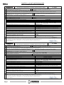
DICHIARAZIONE DI PRESTAZIONE IN ACCORDO CON IL REGOLAMENTO (UE) 305/2011
DECLARATION OF PERFORMANCE ACCORDING TO REGULATION (EU) 305/2011 N° 70R2
1
Codice di identificazione unico del prodotto-tipo: BELLAVISTA R2 SILENT
Unique identification code of the product type:
2
Modello, lotto, serie ai sensi dell'articolo 11, paragrafo 4: BELLAVISTA R2 SILENT
Model, batch or serial number required under Article 11(4):
3
Usi previsti del prodotto da costruzione, conformemente alla relativa specifica tecnica armonizzata:
Intended uses of the construction product, in accordance with the applicable harmonised technical specification:
Apparecchio per il riscaldamento domestico, senza acqua, alimentato a pellet di legno / Residential space heating appliance without water fired by wood pellets
4
Nome registrato e indirizzo del fabbricante ai sensi dell'articolo 11, paragrafo 5:
Namek and contact address of the manufacturer as required pursuant Article 11( 5):
THERMOROSSI S.P.A. Via Grumolo, n° 4 36011 Arsiero (VI)
5
Nome e indirizzo del mandatario ai sensi dell’articolo 12, paragrafo 2:
Name and address of the agent as required pursuant Article 12( 2):
-
6
Sistema di valutazione e verifica della costanza della prestazione del prodotto da costruzione di cui all'allegato V: Sistema 3 e 4
System of assessment and verification of constancy of performance of the construction product as set out in Annex V: System 3 and 4
7
Laboratorio notificato: Notified laboratory:
KIWA CERMET ITALIA S.p.A. N° 0476
Numero del rapporto di prova secondo il sistema 3 / Test report number based on System 3:
2001795/02
8
Prestazione dichiarata / Declared performance
Specifica tecnica armonizzata/Harmonized technical specification:
EN 14785:2006
Caratteristiche Essenziali / Essential characteristics
Prestazione / Performance
Reazione al fuoco / Reaction to fire
A1
Distanza da materiali combustibili
Distance to combustible materials
Minime distanze / Minimum distances (mm):
posteriore/rear = 200 lati/sides = 400 frontale / front = 1.000
soffitto/ceiling = - pavimento / floor = -
Rischio di fuoriuscita di braci incandescenti / Risk of burning fuel falling out
Conforme/Compliant
Temperatura superficiale/Surface temperature
Conforme/Compliant
Sicurezza elettrica / Electrical safety
Conforme/Compliant
Pulizia / Cleanability
Conforme/Compliant
Emissione di prodotti della combustione /Emission of combustion products
CO = 65,0 mg/m3 a potenza termica nominale / CO at Nominal heat output
CO = 429,0 mg/m
3
a potenza termica ridotta / CO at Reduced heat output
Pressione massima di esercizio / Maximum operating pressure
- bar
Temperatura fumi a potenza termica nominale / Flue gas temperature at nominal heat output
T 187 °C
Resistenza meccanica (per sopportare il camino) / Mechanical resistance (to carry a
chimney)
NPD {No Determined Performance}
Potenza termica nominale / Nominal heat output
Potenza termica resa in ambiente / Room heating output
Potenza termica ceduta all’acqua / Water heating output
8,98 kW
8,98 kW
-,-- kW
Rendimento / Efficiency
85,36 % alla potenza termica nominale / Nominal heat output
85,26 % alla potenza termica ridotta / Reduced heat output
9
La prestazione del prodotto di cui ai punti 1 e 2 è conforme alla prestazione dichiarata di cui al punto 8. Firma/Signature:
Si rilascia la presente dichiarazione di prestazione sotto la responsabilità esclusiva del fabbricante di cui al punto 4.
The performance of the product identified in points 1 and 2 is in conformity with the declared performance in point 8.
This declaration of performance is issued under the sole responsibility of the manufacturer identified in point 4.
Arsiero, 25/06/2020
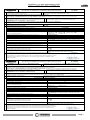
DICHIARAZIONE DI PRESTAZIONE IN ACCORDO CON IL REGOLAMENTO (UE) 305/2011
DECLARATION OF PERFORMANCE ACCORDING TO REGULATION (EU) 305/2011 N° 70AR2
1
Codice di identificazione unico del prodotto-tipo: BELLAVISTA R2 PLUS
Unique identification code of the product type:
2
Modello, lotto, serie ai sensi dell'articolo 11, paragrafo 4: BELLAVISTA R2 PLUS
Model, batch or serial number required under Article 11(4):
3
Usi previsti del prodotto da costruzione, conformemente alla relativa specifica tecnica armonizzata:
Intended uses of the construction product, in accordance with the applicable harmonised technical specification:
Apparecchio per il riscaldamento domestico, senza acqua, alimentato a pellet di legno / Residential space heating appliance without water fired by wood pellets
4
Nome registrato e indirizzo del fabbricante ai sensi dell'articolo 11, paragrafo 5:
Namek and contact address of the manufacturer as required pursuant Article 11( 5):
THERMOROSSI S.P.A. Via Grumolo, n° 4 36011 Arsiero (VI)
5
Nome e indirizzo del mandatario ai sensi dell’articolo 12, paragrafo 2:
Name and address of the agent as required pursuant Article 12( 2):
-
6
Sistema di valutazione e verifica della costanza della prestazione del prodotto da costruzione di cui all'allegato V: Sistema 3 e 4
System of assessment and verification of constancy of performance of the construction product as set out in Annex V: System 3 and 4
7
Laboratorio notificato: Notified laboratory:
ACTECO s.r.l. N.B. n°1880
Numero del rapporto di prova secondo il sistema 3 / Test report number based on System 3:
1880-CPR-010-20
8
Prestazione dichiarata / Declared performance
Specifica tecnica armonizzata/Harmonized technical specification:
EN 14785:2006
Caratteristiche Essenziali / Essential characteristics
Prestazione / Performance
Reazione al fuoco / Reaction to fire
A1
Distanza da materiali combustibili
Distance to combustible materials
Minime distanze / Minimum distances (mm):
posteriore/rear = 200 lati/sides = 400 frontale / front = 1.000
soffitto/ceiling = - pavimento / floor = -
Rischio di fuoriuscita di braci incandescenti / Risk of burning fuel falling out
Conforme/Compliant
Temperatura superficiale/Surface temperature
Conforme/Compliant
Sicurezza elettrica / Electrical safety
Conforme/Compliant
Pulizia / Cleanability
Conforme/Compliant
Emissione di prodotti della combustione /Emission of combustion products
CO = 39,0 mg/m3 a potenza termica nominale / CO at Nominal heat output
CO = 206,0 mg/m
3
a potenza termica ridotta / CO at Reduced heat output
Pressione massima di esercizio / Maximum operating pressure
- bar
Temperatura fumi a potenza termica nominale / Flue gas temperature at nominal heat output
T 167 °C
Resistenza meccanica (per sopportare il camino) / Mechanical resistance (to carry a
chimney)
NPD {No Determined Performance}
Potenza termica nominale / Nominal heat output
Potenza termica resa in ambiente / Room heating output
Potenza termica ceduta all’acqua / Water heating output
11,10 kW
11,10 kW
-,-- kW
Rendimento / Efficiency
90,70 % alla potenza termica nominale / Nominal heat output
87,90 % alla potenza termica ridotta / Reduced heat output
9
La prestazione del prodotto di cui ai punti 1 e 2 è conforme alla prestazione dichiarata di cui al punto 8. Firma/Signature:
Si rilascia la presente dichiarazione di prestazione sotto la responsabilità esclusiva del fabbricante di cui al punto 4.
The performance of the product identified in points 1 and 2 is in conformity with the declared performance in point 8.
This declaration of performance is issued under the sole responsibility of the manufacturer identified in point 4.
Arsiero, 25/06/2020

Installation, use and maintenance guide
BELLAVISTA R2 – BELLAVISTA S2
Page 4
ENG
DICHIARAZIONE DI PRESTAZIONE IN ACCORDO CON IL REGOLAMENTO (UE) 305/2011
DECLARATION OF PERFORMANCE ACCORDING TO REGULATION (EU) 305/2011 N° 75S2
1
Codice di identificazione unico del prodotto-tipo: BELLAVISTA S2 SILENT
Unique identification code of the product type:
2
Modello, lotto, serie ai sensi dell'articolo 11, paragrafo 4: BELLAVISTA S2 SILENT
Model, batch or serial number required under Article 11(4):
3
Usi previsti del prodotto da costruzione, conformemente alla relativa specifica tecnica armonizzata:
Intended uses of the construction product, in accordance with the applicable harmonised technical specification:
Apparecchio per il riscaldamento domestico, senza acqua, alimentato a pellet di legno / Residential space heating appliance without water fired by wood pellets
4
Nome registrato e indirizzo del fabbricante ai sensi dell'articolo 11, paragrafo 5:
Namek and contact address of the manufacturer as required pursuant Article 11( 5):
THERMOROSSI S.P.A. Via Grumolo, n° 4 36011 Arsiero (VI)
5
Nome e indirizzo del mandatario ai sensi dell’articolo 12, paragrafo 2:
Name and address of the agent as required pursuant Article 12( 2):
-
6
Sistema di valutazione e verifica della costanza della prestazione del prodotto da costruzione di cui all'allegato V: Sistema 3 e 4
System of assessment and verification of constancy of performance of the construction product as set out in Annex V: System 3 and 4
7
Laboratorio notificato: Notified laboratory:
KIWA CERMET ITALIA S.p.A. N° 0476
Numero del rapporto di prova secondo il sistema 3 / Test report number based on System 3:
2001795/02
8
Prestazione dichiarata / Declared performance
Specifica tecnica armonizzata/Harmonized technical specification:
EN 14785:2006
Caratteristiche Essenziali / Essential characteristics
Prestazione / Performance
Reazione al fuoco / Reaction to fire
A1
Distanza da materiali combustibili
Distance to combustible materials
Minime distanze / Minimum distances (mm):
posteriore/rear = 200 lati/sides = 400 frontale / front = 1.000
soffitto/ceiling = - pavimento / floor = -
Rischio di fuoriuscita di braci incandescenti / Risk of burning fuel falling out
Conforme/Compliant
Temperatura superficiale/Surface temperature
Conforme/Compliant
Sicurezza elettrica / Electrical safety
Conforme/Compliant
Pulizia / Cleanability
Conforme/Compliant
Emissione di prodotti della combustione /Emission of combustion products
CO = 65,0 mg/m3 a potenza termica nominale / CO at Nominal heat output
CO = 429,0 mg/m
3
a potenza termica ridotta / CO at Reduced heat output
Pressione massima di esercizio / Maximum operating pressure
- bar
Temperatura fumi a potenza termica nominale / Flue gas temperature at nominal heat output
T 187 °C
Resistenza meccanica (per sopportare il camino) / Mechanical resistance (to carry a
chimney)
NPD {Nessuna Prestazione Determinata}
Potenza termica nominale / Nominal heat output
Potenza termica resa in ambiente / Room heating output
Potenza termica ceduta all’acqua / Water heating output
8,98 kW
8,98 kW
-,-- kW
Rendimento / Efficiency
85,36 % alla potenza termica nominale / Nominal heat output
85,26 % alla potenza termica ridotta / Reduced heat output
9
La prestazione del prodotto di cui ai punti 1 e 2 è conforme alla prestazione dichiarata di cui al punto 8. Firma/Signature:
Si rilascia la presente dichiarazione di prestazione sotto la responsabilità esclusiva del fabbricante di cui al punto 4.
The performance of the product identified in points 1 and 2 is in conformity with the declared performance in point 8.
This declaration of performance is issued under the sole responsibility of the manufacturer identified in point 4.
Arsiero, 25/06/2020
DICHIARAZIONE DI PRESTAZIONE IN ACCORDO CON IL REGOLAMENTO (UE) 305/2011
DECLARATION OF PERFORMANCE ACCORDING TO REGULATION (EU) 305/2011 N° 75AS2
1
Codice di identificazione unico del prodotto-tipo: BELLAVISTA S2 PLUS
Unique identification code of the product type:
2
Modello, lotto, serie ai sensi dell'articolo 11, paragrafo 4: BELLAVISTA S2 PLUS
Model, batch or serial number required under Article 11(4):
3
Usi previsti del prodotto da costruzione, conformemente alla relativa specifica tecnica armonizzata:
Intended uses of the construction product, in accordance with the applicable harmonised technical specification:
Apparecchio per il riscaldamento domestico, senza acqua, alimentato a pellet di legno / Residential space heating appliance without water fired by wood pellets
4
Nome registrato e indirizzo del fabbricante ai sensi dell'articolo 11, paragrafo 5:
Namek and contact address of the manufacturer as required pursuant Article 11( 5):
THERMOROSSI S.P.A. Via Grumolo, n° 4 36011 Arsiero (VI)
5
Nome e indirizzo del mandatario ai sensi dell’articolo 12, paragrafo 2:
Name and address of the agent as required pursuant Article 12( 2):
-
6
Sistema di valutazione e verifica della costanza della prestazione del prodotto da costruzione di cui all'allegato V: Sistema 3 e 4
System of assessment and verification of constancy of performance of the construction product as set out in Annex V: System 3 and 4
7
Laboratorio notificato: Notified laboratory:
ACTECO s.r.l. N.B. n°1880
Numero del rapporto di prova secondo il sistema 3 / Test report number based on System 3:
1880-CPR-010-20
8
Prestazione dichiarata / Declared performance
Specifica tecnica armonizzata/Harmonized technical specification:
EN 14785:2006
Caratteristiche Essenziali / Essential characteristics
Prestazione / Performance
Reazione al fuoco / Reaction to fire
A1
Distanza da materiali combustibili
Distance to combustible materials
Minime distanze / Minimum distances (mm):
posteriore/rear = 200 lati/sides = 400 frontale / front = 1.000
soffitto/ceiling = - pavimento / floor = -
Rischio di fuoriuscita di braci incandescenti / Risk of burning fuel falling out
Conforme/Compliant
Temperatura superficiale/Surface temperature
Conforme/Compliant
Sicurezza elettrica / Electrical safety
Conforme/Compliant
Pulizia / Cleanability
Conforme/Compliant
Emissione di prodotti della combustione /Emission of combustion products
CO = 39,0 mg/m3 a potenza termica nominale / CO at Nominal heat output
CO = 206,0 mg/m
3
a potenza termica ridotta / CO at Reduced heat output
Pressione massima di esercizio / Maximum operating pressure
- bar
Temperatura fumi a potenza termica nominale / Flue gas temperature at nominal heat output
T 167 °C
Resistenza meccanica (per sopportare il camino) / Mechanical resistance (to carry a
chimney)
NPD {No Determined Performance}
Potenza termica nominale / Nominal heat output
Potenza termica resa in ambiente / Room heating output
Potenza termica ceduta all’acqua / Water heating output
11,10 kW
11,10 kW
-,-- kW
Rendimento / Efficiency
90,70 % alla potenza termica nominale / Nominal heat output
87,90 % alla potenza termica ridotta / Reduced heat output
9
La prestazione del prodotto di cui ai punti 1 e 2 è conforme alla prestazione dichiarata di cui al punto 8. Firma/Signature:
Si rilascia la presente dichiarazione di prestazione sotto la responsabilità esclusiva del fabbricante di cui al punto 4.
The performance of the product identified in points 1 and 2 is in conformity with the declared performance in point 8.
This declaration of performance is issued under the sole responsibility of the manufacturer identified in point 4.
Arsiero, 25/06/2020

Installation, use and maintenance guide
BELLAVISTA R2 – BELLAVISTA S2
Page 5
ENG
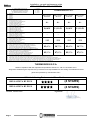
IT – SCHEDA PRODOTTO (UE 2015/1186)
EN – PRODUCT FICHE (EU 2015/1186)
FR – FICHE PRODUIT (UE 2015/1186)
NL – PRODUCTGEGEVENSBLAD (EU 2015/1186)
DE – PRODUKTDATENBLATT (EU 2015/1186)
ES – FICHA DE PRODUCTO (UE 2015/1186)
IT – MARCHIO
EN – BRAND
FR – MARQUE
NL – MERK
DE – MARKE
ES – MARCA
THERMOROSSI S.P.A.
IT – MODELLO
EN – MODEL
FR – MODÈLE
NL – MODEL
DE – MODELL
ES – MODELO
BELLAVISTA
R2 SILENT
BELLAVISTA
R2 PLUS
BELLAVISTA
S2 SILENT
BELLAVISTA
S2 PLUS
IT – CLASSE DI EFFICIENZA ENERGETICA
EN – ENERGY EFFICIENCY CLASS
FR – CLASSE D'EFFICACITÉ ÉNERGÉTIQUE
NL – ENERGIE EFFICIENTIEKLASSE
DE – ENERGIEEFFIZIENZKLASSE
ES – CLASE DE EFICIENCIA ENERGÉTICA
A+ A+ A+ A+
IT – POTENZA TERMICA DIRETTA
EN – DIRECT HEAT OUTPUT
FR – PUISSANCE THERMIQUE DIRECTE
NL – DIREKTE WARMTEAFGIFTE
DE – DIREKTE WÄRMELEISTUNG
ES – POTENCIA CALORÍFICA DIRECTA
9,0 kW 11,1 kW 9,0 kW 11,1 kW
IT – POTENZA TERMICA INDIRETTA
EN – INDIRECT HEAT OUTPUT
FR – PUISSANCE THERMIQUE INDIRECTE
NL – INDIRECTE WARMTEAFGIFTE
DE – INDIREKTE WÄRMELEISTUNG
ES – POTENCIA CALORÍFICA INDIRECTA
- - - -
IT – INDICE DI EFFICIENZA ENERGETICA
EN – ENERGY EFFICIENCY INDEX
FR – INDICE D'EFFICACITÉ ÉNERGÉTIQUE
NL – ENERGIE-EFFICIENTIE-INDEX
DE – ENERGIEEFFIZIENZINDEX
ES – ÍNDICE DE EFICIENCIA ENERGÉTICA
113 121 113 121
IT – EFFICIENZA UTILE ALLA POTENZA TERMICA NOMINALE
EN – USEFUL ENERGY EFFICIENCY AT NOMINAL HEAT OUTPUT
FR – RENDEMENT UTILE À LA PUISSANCE THERMIQUE NOMINALE
NL – NUTTIG RENDEMENT BIJ NOMINAAL VERMOGEN
DE – BRENNSTOFF-ENERGIEEFFIZIENZ BEI NENNWÄRMELEISTUNG
ES – EFICIENCIA ENERGÉTICA ÚTIL A POTENCIA CALORÍFICA NOMINAL
85,4 % 90,7 % 85,4 % 90,7 %
IT – EFFICIENZA UTILE AL CARICO MINIMO
EN – USEFUL ENERGY EFFICIENCY AT MINIMUM LOAD
FR – RENDEMENT UTILE À LA CHARGE MINIMALE
NL – NUTTIG RENDEMENT BIJ MINIMALE WARMTEAFGIFTE
DE – BRENNSTOFF-ENERGIEEFFIZIENZ BEI MINDESTLAST
ES – EFICIENCIA ENERGÉTICA ÚTIL A CARGA MINIMA
85,3 % 87,9 % 85,3 % 87,9 %
IT – RISPETTARE TUTTE LE ISTRUZIONI RIPORTATE SUL MANUALE DI INSTALLAZIONE USO E MANUTENZIONE
EN – ALWAYS FOLLOW THE INSTRUCTIONS PROVIDED IN THE OPERATING AND MAINTENANCE MANUAL
FR – RESPECTER TOUTES LES INSTRUCTIONS CITÉES DANS LA NOTICE D’INSTALLATION, UTILISATION ET ENTRETIEN
NL – VOLG ALTIJD DE INSTRUCTIES VAN DE INSTALLATIE-, GERUIKERSHANDLEIDING EN DE ONDERHOUDSVOORSCHRIFTEN
DE – ERFÜLLEN DIE ANWEISUNGEN DER INSTALLATION, NUTZUNG UND WARTUNG, DIE IN DER ANLEITUNGSBUCH SIND
ES – RESPECTAR LAS INSTRUCCIONES REPORTADAS EN EL MANUAL DE UTILIZACIÓN Y MANTENIMIENTO
THERMOROSSI S.P.A.
certifies compliance with the requirements specified in Decree no. 186 of 7 November 2017:
“Regulation establishing the requirements, procedures and responsibilities for the issuing of certification for heat
generators powered by solid biomass fuel”:
With the following Environmental Classification:
BELLAVISTA R2 PLUS (4 STARS)
BELLAVISTA R2 PLUS (4 STARS)
Arsiero, 25/06/2020 Signature:

Installation, use and maintenance guide
BELLAVISTA R2 – BELLAVISTA S2
Page 6
ENG
1 – INTRODUCTION
1.1 SAFETY GUIDELINES
This installation, use and maintenance manual is an integral and essential part of the product and must be kept by the user. Before
commencing with the installation, use and maintenance of the product, carefully read this guide. All local, national and European
regulations regarding the installation and use of the appliance must be met. The Manufacturer recommends carrying out all the
maintenance operations described in this manual.
This appliance must only be used as intended by the manufacturer. Any other use is considered incorrect and therefore hazardous;
consequently, the user shall be totally liable for the product if used improperly. Installation, maintenance and repairs must be carried
out by professionally qualified personnel, certified according to Decree no. 37 of 22 January 2008 and in compliance with current
regulations. In case of repairs only original spare parts supplied by the manufacturer must be used. Incorrect installation or poor
maintenance can injure or damage people, animals or things; in this case the manufacturer shall be relieved of all responsibility.
Before beginning any cleaning or maintenance operation switch off the appliance by means of the 0/I main switch and disconnect
the plug from the electrical power socket. The product must be installed in suitable locations and furnished with all the services
(power and outlets) which the appliance requires for a correct and safe operation. Any repairs or actions carried out on any
systems, components or internal parts of the appliance, or on any of the accessories supplied with it, that are not specifically
authorised by Thermorossi S.p.A, will automatically void the warranty and the manufacturer's responsibility, pursuant to Italian
Decree no. 224 of the President of the Republic of 24/05/1988, art. 6/b.
It is recommended to keep this manual in a safe place that is easily accessible to all users; if the manual is lost or deteriorated
contact the manufacturer for a replacement copy. If the appliance is sold or transferred to another user ensure that the manual is
handed over with it. The images and figures featured in this manual are purely illustrative and may differ from the actual product.
Furthermore, Thermorossi reserves the right to apply changes to the content of this manual anytime and without notice.
Thermorossi S.p.A. retains copyright on this manual. These instructions may not be reproduced or communicated to third parties or
used in any other way without the necessary authorisation.
1.2 SAFETY STANDARDS
PERSONAL INJURY
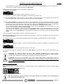
This safety symbol identifies important messages throughout the manual. Read the information marked by this symbol
carefully as non-observance of this message can cause serious injury to persons using the appliance.
DAMAGE TO PROPERTY
This safety symbol identifies messages or instructions that are fundamental for the generator to function well. To avoid
serious damage to the appliance adhere strictly to these instructions.
INFORMATION
This symbol indicates important instructions for good functioning of the generator. If this information is not correctly
observed, the performance of the appliance will not be satisfactory.
1.3 RECOMMENDATIONS
Before using the appliance, carefully read every section of this installation, use and maintenance guide as knowledge
of the information and the regulations contained in it are essential for a correct use of the appliance.
The entire operation concerning the connection of the electric panel must be carried out by expert personnel; no
responsibility will be accepted for damages, even to third parties, if the instructions for installation, use and
maintenance of the appliance are not followed scrupulously. Modifications made to the appliance by the user or on
his behalf, must be considered to be under his complete responsibility. The user is responsible for all the operations
required for the maintenance of the appliance before and during its use.
1.4 GENERAL GUIDELINES
Attention: the appliance must be connected to a system provided with a PE conductor (in compliance with the
specifications concerning low voltage equipment). Before installing the appliance check the efficiency of the earth
circuit of the power supply system.
Attention: the power supply line must have a section which is suitable for the power of the equipment. The cable section must in any
case be no less than 1.5 mm². The appliance requires powering with a voltage of 230V and 50 Hz. Voltage variations greater than
10% of the nominal value can cause irregular operation or damage the electrical device. Position the appliance so that the electric
power outlet in the room is easily accessible. Ensure that a suitable differential switch is installed upstream from the equipment.
Position the power supply cable in order to prevent any contact of the latter with the smoke exhaust pipe or hot parts of the
appliance. If the power cord is damaged it must be replaced by the manufacturer or by an authorised technical assistance service in
order to avoid risks.
Your appliance has obtained the CE marking and has been made to run for 1 hour to check that it functions correctly.
The product must not be used by children under the age of 8 years, by persons with physical, mental or sensorial impairments, or
by persons who are not familiar with the instructions for use and maintenance of the product (the instructions are found in this
booklet). Children must not play with the appliance.

Installation, use and maintenance guide
BELLAVISTA R2 – BELLAVISTA S2
Page 7
ENG
ATTENTION: Before every use make sure that the burner and the ash pan are clean, and check that the sliding door is firmly
closed and air tight.
ATTENTION: the sliding door must always remain shut tight when the appliance is operating. It is strictly forbidden to open the
sliding door while the appliance is in operation. While the appliance is in operation the smoke exhaust pipes and some parts of the
appliance itself can reach extremely high temperatures: do not touch them! Do not expose your body to hot air for long, do not
overheat the room in which the appliance is installed, as these actions could cause health problems. Do not expose plants or
animals directly to the hot air flow as this could have noxious effects on them. It is strictly prohibited to use any type of fuel (liquid,
solid...) to light up the appliance: lighting must occur automatically as intended and described in this installation, use and
maintenance booklet; consequently, it is also strictly forbidden to feed pellets (or any other material) into the brazier. Do not place
non-heat resistant or inflammable or combustible objects in the vicinity of the appliance: keep them at a suitable distance. Do not
place wet clothing to dry on the appliance. When using a clothes horse, keep at a suitable distance. It is strictly prohibited to
disconnect the appliance from the electrical power mains while it is in operation.
Caution: do not wet the appliance and do not touch the electrical parts with wet hands. Never vacuum hot ash: this
could damage the vacuum device. All the cleaning operations described in this manual must be carried out when the
appliance is cold.
Attention! Warning for Swiss users
Refer to the local cantonal regulations imposed by the Fire Department (Mandatory signalling and safety distances)
and the Note concerning installation of heaters issued by the Association of Cantonal Fire Agencies (VKF - AEAI).
ATTENTION: it is mandatory to earth the appliance. If this instruction is not observed serious damage, which is not
covered by warranty, will result to the body of the appliance. Have an electrician check the earthing. There must be
no electric potential (Volt) between the earth of the generator and the actual earth of the system.
1.5 TRANSPORTATION AND STORAGE
TRANSPORTATION AND HANDLING
The appliance body must always be in a vertical position when handled and exclusively by means of trolleys. Take special care to
protect the electric panel, the glass, and all the fragile parts from mechanical impact which could damage them and their correct
functioning.
STORAGE
The appliance must be stored in a humid-free environment and sheltered from the weather; avoid placing the appliance directly on
the ground. The Company denies all responsibility for damage caused to wood floors or floors made from any other material.
It is inadvisable to store the product for long periods of time.
1.6 GUIDELINES FOR CORRECT DISPOSAL OF THE PRODUCT
At the end of the product’s useful life it must be disposed of in compliance with applicable regulations and in respect
of the environment, not with urban waste. The product must be consigned to designated sorted waste collection
centres for the disposal of electronic waste authorised by the local municipal councils. Correct disposal not only helps
safeguard the environment but it also promotes recovery and recycling of the materials.

Installation, use and maintenance guide
BELLAVISTA R2 – BELLAVISTA S2
Page 8
ENG
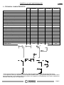
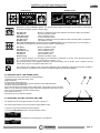
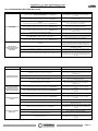
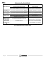
2 – TECHNICAL CHARACTERISTICS
M.U. BELLAVISTA
R2 SILENT
BELLAVISTA
R2 PLUS
BELLAVISTA
S2 SILENT
BELLAVISTA
S2 PLUS
Height mm 1,493 1,493 1,489 1,489
Depth mm 667 – 975 667 – 975 674 - 975 674 - 975
Width mm 480 480 431 431
Empty weight Kg 183 183 183 183
Firebox power (Min. / Max.)* kW 3.89 / 10.52 4.43 / 12.20 3.89 / 10.52 4.43 / 12.20
Rated power Min. / Max.* kW 3.31 / 8.98 3.89 / 11.10 3.31 / 8.98 3.89 / 11.10
Consumption (Min. / Max.)* Kg/h 0.83 / 2.24 0.94 / 2.47 0.83 / 2.24 0.94 / 2.47
Ø smoke exhaust pipe mm 100 100 100 100
Min. draught at rated power
Pa
12
12
12
12
Min. draught at reduced power Pa 12 12 12 12
Tank capacity Kg 25 25 25 25
Average smoke temperature at rated power* °C 187 167 187 167
Average smoke temperature at reduced power* °C 109 93 109 93
Smoke flow at rated power*
g/s
8.0
7.0
8.0
7.0
Smoke flow at reduced power* g/s 6.1 7.0 6.1 7.0
Efficiency at rated power* % 85.36 90.70 85.36 90.70
Efficiency at reduced power* % 85.26 87.90 85.26 87.90
CO emissions with 13% O2 at rated power* mg/m3 65 39 65 39
CO emissions with 13% O2 at reduced power* mg/m3 429 206 429 206
Power supply voltage and frequency V / Hz 230 V / 50 Hz 230 V / 50 Hz 230 V / 50 Hz 230 V / 50 Hz
Max electrical consumption A / W 1.40 – 320 1.40 - 320 1.40 – 320 1.40 - 320
Min electrical consumption A / W 0.27 – 60 0.31 - 70 0.27 – 60 0.31 - 70
Heatable volume** m3 240 285 240 285
* All the data are based on the appliance fuelled with standards UNI EN 14961-2 A1 and A2 type-approved pellets.
** It is important to take into consideration the fact that the heatable volume is greatly influenced by the insulation of the
house (energy class of the building) and by the position of the appliance in the planimetry of the house, therefore the
indicated values may vary, even significantly.

Installation, use and maintenance guide
BELLAVISTA R2 – BELLAVISTA S2
Page 9
ENG
3 – GENERAL DESCRIPTION
3.1 OPERATING TECHNOLOGY
Your appliance has been built to fully satisfy all your heating and practical requirements. Top-grade components and functions
managed with microprocessor technology guarantee high reliability and optimal performance.
3.2 THE PELLET
The appliance is fuelled by pellets, that is, cylinders of compressed sawdust; it his allows you to fully enjoy the heat of the flame
without having to manually stoke the combustion.
The pellets have a 6 mm diameter and a length between 10 e 20 mm. They have a max moisture content of 8%; a thermal value of
4000/4500 Kcal/kg and density of 630-640 kg/m³. It must be approved according to UNI EN 14961-2 A1 A2.
It is strictly forbidden to use any pellet type other than that specified above. The use of fuel that does not comply with the
above specifications not only immediately invalidates the warranty for the appliance but can also create dangerous
situations. Do not use the appliance as an incinerator, at the risk of voiding the warranty.
3.3 PELLET REFUELLING
The pellet feedbox is situated in the top part of the appliance. The load
capacity specified in the technical data can vary according to the specific
weight of the pellets.
Take special care when loading the tank as the screw feeder at its base is
in motion. Take care when topping up with fuel as the loading area can
get very hot.
ATTENTION: it is normal to find some pellets remaining in the tank even if
the stove shuts off because the pellets have run out.
Attention: when filling up the tank, take care not to drop any pellets into
the internal parts of the appliance, as, in extreme cases, this could
generate live flames.
The manufacturer recommends emptying the tank and vacuuming the screw feeder zone once a month and during the
summer period. If the screw feeder can be seen when loading the pellet in the tank (pellet almost exhausted in the tank),
the appliance must be turned off, cooled down and the brazier must be cleaned. Do not switch off the appliance by
means of the main switch O/I on the power panel or by cutting off the power supply. Then restart the appliance.
Should you notice an excessive stagnation of flue gas in the combustion chamber, move away from the appliance
immediately. In particular move away from the glass sliding door of the combustion chamber. The excessive
concentration of unburned gases could create an explosion that could break the glass. Do not open the sliding door of
the combustion chamber for any reason and do not go near the appliance until said gases have been exhausted. Contact
a technical service centre to determine the causes. Do not switch off the appliance by means of the main switch O/I on
the power panel or by cutting off the power supply. Do not turn on the appliance for any reason whatsoever following an
event such as this.
Only pellets complying with the above specifications are to be loaded into the tank; in no case whatsoever must foreign
substances or objects be introduced into the tank, the brazier or any part of the generator.

Installation, use and maintenance guide
BELLAVISTA R2 – BELLAVISTA S2
Page 10
ENG
4 - INSTALLATION
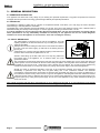
4.1 APPLIANCE LOCATION
Follow the general guidelines set out in paragraph 1.1 to the letter. Keep in mind that the flooring of the room in which
the appliance is to be installed must withstand the combined weight of the appliance and the pellets contained in the
tank.
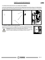
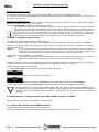
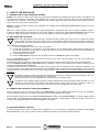
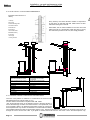
ATTENTION: The room where the appliance is installed must be well-ventilated and free
from humidity and salty air. A high level of humidity or saltiness in the room can lead to
the onset of rust or corrosion which will not be covered by warranty. The appliance must
be positioned at a minimum safe distance from walls and furnishings. If inflammable
materials are located in the vicinity of the appliance (e.g.: matchboarding, furniture,
curtains, pictures and paintings, sofas) it is mandatory to comply with the minimum
distances illustrated (see figure at right) Installation in the vicinity of heat-sensitive
materials is only permitted if suitable insulating and fireproof protection is placed
between the object and the appliance (ref. Uni 10683).
If the flooring is made of wood or any other combustible material, it is mandatory to install
a fireproof floor protector plate between the appliance and the floor. Failure to observe this
instruction will immediately invalidate the appliance warranty.
The installer must issue a certificate of conformity for the installation which includes the design plans and the following documents:
a) Report containing the type of materials utilised.
b) Project as defined in Article 5 of Ministerial Decree n° 37 22 January 2008.
c) Drawing of the finished installation.
d) References to existing partial or previous declarations of conformity (e.g. electrical wiring).
e) Copy of the certificate of recognition of the professional technical qualifications.
These documents must, by law, be kept together with the use and maintenance booklet. The customer is responsible
for verifying, directly or indirectly, that the installation has been carried out to perfection in accordance with relevant
regulations in force. Do not install the appliance in unsuitable rooms such as bedrooms, bathrooms, garages and/or
lock-ups. It is forbidden to place the appliance in environments with an explosive atmosphere.
ATTENTION, the appliance is not simply a household appliance: if the instructions set out in this booklet are not
followed and/or if installation of the appliance is not executed perfectly and/or the provisions in force are not strictly
complied with, dangerous conditions could arise for both objects and persons. It is the user’s responsibility to verify the
presence, in the room, of a vent necessary for supplying oxygen to the generator.
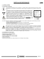
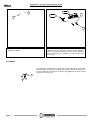
4.2 UNPACKING THE APPLIANCE
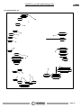
Proceed as follows to unpack the appliance:
1) Remove the top of the wooden crate (A).
2) Remove the polystyrene (B).
3) Remove the sides (C) of the wooden packaging.
4) Remove the sides (D) of the wooden packaging.
5) Open the sliding door.
6) Remove the screws (E).
7) Now remove the product from the pallet, making sure not to damage it during handling.
A = 1,000 mm
L = 400 mm
P = 200 mm

Installation, use and maintenance guide
BELLAVISTA R2 – BELLAVISTA S2
Page 11
ENG
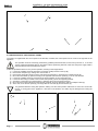
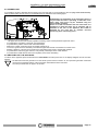
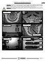
4.3 RELOCATION OF THE CONTROL PANEL
The product is supplied with the control panel on the left side; if needed, the control panel can be moved to the right side of the
appliance.
This operation must be exclusively performed by qualified professional staff, as set forth by Decree no. 37 of 22nd
January 2008 and applicable laws on the subject. Before performing said task, make sure the power supply cable is
disconnected from the electrical power socket.
Follow the procedures below to carry out this operation, referring to the images below:
1) Loosen the 2 Philips screws at the bottom (A) and the 3 Philips screws at the top (B).
2) Remove the rear panel (C), making sure not to scratch it.
3) Remove the metal sheet top (E) from the rear panel just removed (C), loosening the 3 Philips screws (D).
4) Mount the metal sheet top just removed (E) in the opposite side of the rear panel (C), so as to close the hole.
5) Loosen the 4 Philips screws (F) and remove the sheet protection of the control panel (G).
6) Loosen the two nuts (H) in order to remove the control panel (1) from the supporting bracket.
7) Secure the control panel (I) to the bracket (L), tightening the 2 nuts previously loosened.
8) Mount and secure the metal sheet protection (G) previously removed, fastening it with the 4 Philips screws (F).
9) At the end, mount the rear panel (C), securing it with the 3 screws (B) and two screws (A).
Pay particular attention during this operation, making sure the control panel's cable does not come into contact with
the hot or moving parts of the appliance. If said rule is not abided to, the cable may be damaged thus voiding the
warranty.

Installation, use and maintenance guide
BELLAVISTA R2 – BELLAVISTA S2
Page 12
ENG
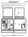
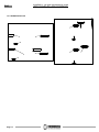
4.4 INSTALLATION OF AIRBOX 3 VENTILATION KIT (OPTIONAL)
Airbox 3 ventilation kit can be installed on the appliance. By introducing this optional, the appliance will become Plus, therefore
ventilated and ductable. Once the kit is connected, all parameters required to transform the product from Silent to Plus will be pre-
loaded automatically, with the possibility to change the fan's speed directly from the control display.
This operation must be exclusively performed by qualified professional staff, as set forth by Decree no. 37 of 22nd
January 2008 and applicable laws on the subject. Before performing said task, make sure the power supply cable is
disconnected from the electrical power socket.
Follow the procedures below to install Airbox 3 ventilation kit:
1) Unpack the ventilation kit.
3) Introduce the condenser (B) in the specific hole, fasten
it with bolt (C) and couple connector (E) with connector
(F). At the end, push the fan inside until the end-stop.
4) Remove the filter (G) and secure the fan at the top by
means of bolt (H) and washer (I).
2) Remove the plug (A) from the appliance,
pulling downward

Installation, use and maintenance guide
BELLAVISTA R2 – BELLAVISTA S2
Page 13
ENG
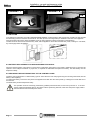
4.5 HANDLE
Your appliance is supplied with a handle (B) to open and close the combustion
chamber sliding door and thus proceed with cleaning operations. When not in
use, the handle can be stowed on the back of the appliance if the hook provided
is attached to the stove. (A).
5) Unscrew the 4 knobs (A) and remove the cast-iron top
(B), pulling it upward.
6) Insert deflectors (C – sx/LH) and (C – dx/RH). Open the
sliding door of the combustion chamber (for this operation,
refer to the specific chapter) and secure the two deflectors
with 4 screws (E) and 4 washers (D). Then re-fit the cast-
iron top (B).

Installation, use and maintenance guide
BELLAVISTA R2 – BELLAVISTA S2
Page 14
ENG
4.6 OPENING THE SLIDING DOOR OF THE COMBUSTION CHAMBER
To open and close the sliding door of the combustion chamber, release the fastening hook (B) by acting on the suitable handle. In
the same way, release fastening hook (C) also by acting on the suitable handle. At the end of this operation, it is recommended to
remove the handle in order to avoid opening the door accidentally. Open the door only for cleaning operations and exclusively with
the appliance cooled off and disconnected from electric power.
4.7 DRAWING COMBUSTION AIR FROM OUTSIDE
The appliance is fitted with an intake to enable drawing in the combustion air directly from outside the
building. Connect the air intake on the appliance to the exterior of the building with suitable piping,
capable of resisting high temperatures. The pipe’s length must be maximum 600 mm.
ATTENTION: The suction duct must be protected with a grid and never be clogged.
The protection grid, if installed, must be inspected and cleaned on a monthly basis.
Moreover, a suitable windbreak fitting must be installed in the duct’s terminal.

Installation, use and maintenance guide
BELLAVISTA R2 – BELLAVISTA S2
Page 15
ENG
5 – DESCRIPTION OF THE CONTROLS
The appliance, when operating, could be hot to the touch, particularly the glass of the combustion chamber: take care
when handling the appliance components. Your appliance has obtained the CE marking and has been made to run for
at least one hour to check that it functions correctly. The product must not be used by children, by persons with physical
or mental impairments, by persons who are not familiar with the instructions for use and maintenance of the product
(the instructions are found in this use and maintenance booklet).
ATTENTION: before each use make sure that the burner is always very clean.
ATTENTION: during operation, the sliding door of the combustion chamber must always remain properly closed. It is
strictly forbidden to open the door while the appliance is in operation. While the appliance is in operation the smoke
exhaust pipes can reach extremely high temperatures: do not touch them! It is strictly prohibited to use any type of fuel
(liquid, solid...) other than pallet to light up the appliance: lighting must occur automatically as intended and described in
this installation, use and maintenance booklet; consequently, it is also strictly forbidden to feed pellets (or any other
material) into the brazier. Do not place non-heat resistant or inflammable or combustible objects in the vicinity of the
appliance: keep them at a suitable distance. Do not place wet clothing to dry on the appliance. When using a clothes
horse, keep at a suitable distance. It is strictly prohibited to disconnect the appliance from the electrical power mains
during normal operation.
5.1 DESCRIPTION OF THE CONTROL PANEL
The control panel is managed by a microprocessor. The control buttons and the various displays are described below.
The control buttons are:
Clock button
Press this button to activate / deactivate the programming.
Ventilation button (only in the PLUS version)
Press this button to set the desired level of ventilation: Six ventilation levels can be set on this stove. The fan starts
operating as soon as the temperature inside the stove body rises and the smoke thermocouple gives the signal.
The fan stops automatically when the stove body has cooled sufficiently. The fan cannot be disabled during
operation.
Flame button
Pressing this button when the appliance is off activates the START sequence, sets the power of combustion in the
WORK mode or shuts off the appliance by activating the OFF sequence.
Scroll buttons (only in the Menu)
Press MINUS key to lower the value. Press PLUS key to raise the preset value.
Menu button
Press this button to access the main menu. You can scroll the setting screens shown below, which will be
described in detail in the following paragraphs. To access the functions of each subwindow wait a few seconds.
DATE/TIME This button is used to set the day of the week, the hour and minutes.
CRONO This button is used to set the programmed on and off sequences.
LEVEL Is used to change the rotation speed of the smoke suction unit.
THERMOCOMFORT This button is used to activate the connection with the Room Control device (Optional).
SHOW CRONO This button is used to view the parameters programmed with the CRONO function.
Display
The following information can appear on the display:

Installation, use and maintenance guide
BELLAVISTA R2 – BELLAVISTA S2
Page 16
ENG
Displays the preset combustion power, and consequently the pellet consumption, by the number of bars that are
lit up around the flame symbol, using this logic:
One bar lit up: Minimum combustion power (and therefore with minimum pellet consumption)
Two bars lit: Second combustion power
Three bars lit up: Third combustion power
Four bars lit up: Fourth combustion power
Five bars lit up: Maximum combustion power (and therefore with maximum pellet consumption)
No bars lit up: The appliance is OFF
Only in the PLUS version it displays the preset ventilation power, and consequently the room fan speed, by
the number of bars that are lit up around the fan symbol, using this logic:
One bar lit: Minimum ventilation power
Two bars lit: Second ventilation power
Three bars lit up: Third ventilation power
Four bars lit: Fourth ventilation power
Five bars lit: Fifth ventilation power
Six bars lit up: Maximum ventilation power
Dashes appear along the top of the display, and each dash corresponds to one day of the week set by the user
(e.g. 1 corresponds to Monday, 2 corresponds to Tuesday… etc.).
The operating status of the appliance appears below these dashes, that is START, OFF or WORK. And the
current time set by the user appears below this word.
The presence in the display of the clock symbol indicates that the CHRONO programming has been enabled; if
this symbol does not appear it means that the CHRONO programming has been disabled.
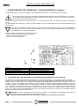
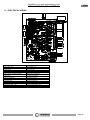
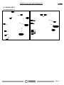
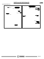
5.2 DESCRIPTION OF THE POWER PANEL
The components of the power board are described below:
1) Electrical power outlet 220V-240V 50Hz
2) Main switch 0/I.
3) Test light for pellet feed motor.
The light comes on simultaneously with the activation of the pellet feed motor.
4) Cap for reset thermostat button.
If the reset thermostat overheats stop the pellet feeder. The appliance must cool down
before you can restart the appliance. After verifying and eliminating the causes of the
event, undo the protective cap and press the button.
5) Protection fuse 3.15 A.
6) Outlet RJ 45 to connect Wi-Fi module.
5.3 DATE/TIME: SETTING THE DATE AND TIME
The appliance must be energised and the I/0 switch in position “I".
The current date and time can be set using the DATE/TIME function.
To set the current time and date proceed as follows:
1) Press the Menu Button once to view the following screen:
2) After a few seconds the following screen will appear on the display:
Legenda
Key
RIARMO
RESET
SPIA MOTORIDUTTORE
GEARMOTOR
INDICATOR
SILENT version
PLUS version

Installation, use and maintenance guide
BELLAVISTA R2 – BELLAVISTA S2
Page 17
ENG
3) Now press the Scroll Buttons to change the day of the week; each number corresponds to one day of the week (e.g. 1
corresponds to Monday, 2 corresponds to Tuesday, etc...). To confirm the selection of the day of the week press the Flame
Button.
Once confirmed, the selector shifts to the hour section while the selected day of the week remains framed:
4) Press the Scroll Buttons to change the hour. Once you have set the hour confirm the value by pressing the Flame Button.
Once confirmed, the selector shifts to the minutes section. Press the Scroll Buttons to set the minutes. Press the Flame
button to confirm.
Once confirmed, the date and time setting screen closes automatically and the initial screen returns to the display.
If you confirm the wrong value simply press the Menu Button several times to exit the box until the initial screen will appear, and
repeat the procedure described above.
5.4 CHRONO: ON/OFF PROGRAMMING
The appliance must be energised and the I/0 switch in position "1".
The CRONO function allows you to set the weekly program by setting up to 3 on-off cycles at different times for every day from
Monday through to Sunday.
To set a program follow the procedure described below:
1) Press the Menu Button twice quickly to view the following screen:
After a few seconds the following screen will appear on the display:
2) Press the Scroll Buttons to select the day of the week on which you want to set the program. Each number corresponds to one
day of the week (e.g. 1 corresponds to Monday, 2 corresponds to Tuesday, etc...). To confirm the day of the week selected for
the programming press the Flame Button. The following screen will appear:
3) Now press the Scroll Buttons to select the hour at which you wish the appliance to start up automatically (ON1). Once the hour
has been set, confirm the value by pressing the Flame Button. When scrolling the ON1 values the OFF1 values will scroll as
well; this is to avoid setting a shut off time that is earlier than the start up time.
Once confirmed, the selector shifts to the minute section of ON1. Press the Scroll Buttons to set the minutes for the first start
up. Confirm the value by pressing the Flame Button.
4) Now press the Scroll Buttons to select the hour at which you wish the appliance to shut off automatically (OFF1). Once the
hour has been set, confirm the value by pressing the Flame Button.
Once confirmed, the selector shifts to the minute section of OFF1. Press the Scroll Buttons to set the minutes for the first shut
off. Confirm the value by pressing the Flame Button.
At this point the first ON/OFF cycle for the selected day has been set.
The following screen will appear:
At this point if no further programming is required for that day go to point 5-A.
If, on the other hand, you wish to program a second ON/OFF cycle for that day go to point 5-B.
5-A) Press the Menu Button to exit the screen, in order to enable you to program the times for the ON/OFF cycles for the other
days of the week. In this case repeat the instructions from point 2 up to this paragraph.
5-B) Press the Scroll Buttons to select the hour at which you wish the appliance to start up automatically for the second time
(ON2). The start up time will be that set before OFF1; this is to avoid setting a second start up time that is earlier than the
preceeding shut off time. Once the hour has been set, confirm the value by pressing the Flame Button. When scrolling the
ON2 values the OFF2 values will scroll as well; this is to avoid setting a shut off time that is earlier than the start up time.
Once confirmed, the selector shifts to the minute section of ON2. Press the Scroll Buttons to set the minutes for the second
start up. Confirm the value by pressing the Flame Button.
Now press the Scroll Buttons to select the hour at which you wish the appliance to shut off automatically (OFF2). Once the
hour has been set, confirm the value by pressing the Flame Button.

Installation, use and maintenance guide
BELLAVISTA R2 – BELLAVISTA S2
Page 18
ENG
Once confirmed, the selector shifts to the minute section of OFF2. Press the Scroll Buttons to set the minutes for the
second shut off. Confirm the value by pressing the Flame Button.
At this point the second ON/OFF cycle for the selected day has been set.
The following screen will appear:
At this point if no further programming is required for that day go to point 6-A.
If, on the other hand, you wish to program a third ON/OFF cycle for that day go to point 6-B.
6-A) Press the Menu Button to exit the screen, in order to enable you to program the times for the ON/OFF cycles for the other
days of the week. In this case repeat the instructions from point 2 up to this paragraph.
6-B) Press the Scroll Buttons to select the hour at which you wish the appliance to start up automatically for the third time (ON3).
The start up time will be that set before OFF2; this is to avoid setting a third start up time that is earlier than the preceeding
shut off time. Once you have set the hour confirm the value by pressing the Flame Button. When scrolling the ON3 values
the OFF3 values will scroll as well; this is to avoid setting a shut off time that is earlier than the start up time..
Once confirmed, the selector shifts to the minute section of ON3. Press the Scroll Buttons to set the minutes for the third
start up. Confirm the value by pressing the Flame Button.
Now press the Scroll Buttons to select the hour at which you wish the appliance to shut off automatically (OFF3). Once the
hour has been set, confirm the value by pressing the Flame Button. Once confirmed, the selector shifts to the minute
section of OFF3. Press the Scroll Buttons to set the minutes for the third shut off. Confirm the value by pressing the Flame
Button.
At this point the third and final ON/OFF cycle for the selected day has been set.
Alternatively, if you wish to copy the exact same programming for the ON/OFF cycles set for a particular day to the next day simply
press the Ventilation button.
For example: if I want to copy all the programmed ON/OFF cycles set for Monday to Tuesday the following screen will appear:
I press the Ventilation button once again to copy all the cycles programmed for Tuesday to Wednesday. The following screen will
appear:
Using the same logic we can copy the programmed cycles to the other days.
7) To conclude the programming operations simply press the Menu Button several times to exit the screen until the initial screen
will appear.
ATTENTION: The appliance ignores any ON or OFF command programmed with a value of 00:00.
Consequently if you do not wish to use an ON or OFF time setting simply set a value of 00:00. The appliance ignores
any ON or OFF command if the shut off time is set the same as or before the start up time.
ATTENTION: In the event of a programmed cycle on always ensure that the brazier is clean. Failure to clean the
brazier can reduce and/or affect the life of the spark plug as it would be subjected to high temperatures due to poor
cooling. It is recommended to set ON/OFF cycles times lasting no less than 2 hours, in order to save energy and for
the proper operation of the appliance.
Enabling the programmed cycles:
Back in the initial screen, to enable the appliance to carry out the ON/OFF cycles as programmed it is necessary to press the Clock
Button.
The image of a clock will appear on the main screen:
The programmed cycles are now enabled.
When the programmed cycles are enabled (a clock symbol appears on the display) it will not be possible to
use an additional chronothermostat.

Installation, use and maintenance guide
BELLAVISTA R2 – BELLAVISTA S2
Page 19
ENG
Disabling the programmed cycles:
To disable the appliance from carrying out the programmed ON/OFF cycles press the Clock Button once again.
On the display the clock symbol will disappear. This operation disables the weekly program that has been set by the user but does
not delete or reset the times.
Resetting the programmed cycles:
Moreover, it is possible to reset, in other words delete, all the programmed cycles entered by the user by holding down the Clock
Button in the initial screen for approx. five seconds.
The words CLEAR TIMERS will appear momentarily on the screen.
Do not release the button until the text CLEARED appears on the screen. Only the appearance of the words CLEARED
signal that the previously entered programmed cycles have been deleted. When the programmed cycles are active the
operating level at start up, that is the combustion power, will be the same level set before the last time the machine was
shut off: that is, only if it was a programmed shut off, not if the machine was shut off by means of a manual action.
Manual shut down can only be carried out with the programming disabled. If after a manual shut off the programmed
cycle re-enables, at the next programmed start up the appliance will be on the first combustion power level.
5.5 LEVEL: OPERATING LEVEL SETTING
The appliance must be energised and the I/0 switch in position “I".
Your appliance is delivered with an excellent program installed that favours combustion efficiency; the program is called LEVEL 1.
However, if you are using pellets with a higher than normal incidence of residues after combustion in the brazier, it is possible to
select alternative levels:
LEVEL 2 is an operating program that accelerates the speed of the smoke suction unit in proportion to all the combustion
power levels. This level must be set when the user notices a weak, high and very dark flame. Attention: this
modification does not authorise the use of below-standard pellets, or no vacuum in the flue outlet.
If using loosely compressed pellets, you could select:
LEVEL 0: is an operating program that decelerates the speed of the smoke suction unit when using loosely compressed
pellets and/or when the flue outlet has a very high vacuum, over 2 mm water column (20 Pascal).
The pellet consumption value remains unchanged regardless of the selected operating level. These variations will only change the
rotation of the smoke suction unit in the WORK stage, all the other stages will not undergo any changes.
Select the required Level by acting as follows:
1) Press the Menu Button three times quickly and the following box will appear:
After a few seconds the following screen will appear on the display:
2) To change the operating level, hold down a Scroll Button while simultaneously pressing the other Scroll Button.
To set the desired level simply press the Menu Button several times until the initial screen will appear on the display.
The level selection can be made with the appliance OFF or ON. If the change is made while the appliance is running
the difference in the flame will be apparent. It is mandatory to pay particular care when selecting the most appropriate
operating cycle for your installation. After the selection of the operating cycle a thorough cleaning of the brazier is
mandatory.
5.6 ROOM CONTROL: CONNECTION WITH THE ROOM CONTROL DEVICE (OPTIONAL)
See the specific manual for the ROOM CONTROL device (Optional).
5.7 SHOW CRONO: ON-OFF PROGRAMMING DISPLAY
The appliance must be energised and the I/0 switch in position “I".
This function enables you to consult the programmed ON/OFF cycles carried out through the CRONO function.
La pagina si sta caricando...
La pagina si sta caricando...
La pagina si sta caricando...
La pagina si sta caricando...
La pagina si sta caricando...
La pagina si sta caricando...
La pagina si sta caricando...
La pagina si sta caricando...
La pagina si sta caricando...
La pagina si sta caricando...
La pagina si sta caricando...
La pagina si sta caricando...
La pagina si sta caricando...
La pagina si sta caricando...
La pagina si sta caricando...
La pagina si sta caricando...
La pagina si sta caricando...
La pagina si sta caricando...
La pagina si sta caricando...
La pagina si sta caricando...
La pagina si sta caricando...
La pagina si sta caricando...
La pagina si sta caricando...
La pagina si sta caricando...
-
 1
1
-
 2
2
-
 3
3
-
 4
4
-
 5
5
-
 6
6
-
 7
7
-
 8
8
-
 9
9
-
 10
10
-
 11
11
-
 12
12
-
 13
13
-
 14
14
-
 15
15
-
 16
16
-
 17
17
-
 18
18
-
 19
19
-
 20
20
-
 21
21
-
 22
22
-
 23
23
-
 24
24
-
 25
25
-
 26
26
-
 27
27
-
 28
28
-
 29
29
-
 30
30
-
 31
31
-
 32
32
-
 33
33
-
 34
34
-
 35
35
-
 36
36
-
 37
37
-
 38
38
-
 39
39
-
 40
40
-
 41
41
-
 42
42
-
 43
43
-
 44
44


Thermorossi BELLAVISTA R2 Guida d'installazione
- Categoria
- Stufe
- Tipo
- Guida d'installazione
in altre lingue
Documenti correlati
Altri documenti
-
Ravelli Olimpia Use and Maintenance Manual
-
-
 Dimplix Ignite 50 Inch / XLF50-EU Framless Wall Fire Manuale del proprietario
-
-
La Nordica CLEO COMBI Bordeaux Manuale del proprietario
-
La Nordica Violetta Manuale del proprietario
-
La Nordica ASIA BII Manuale del proprietario
-
-
La Nordica Anthea verticale Manuale del proprietario
-
